XMG P801 User manual


Preface
V
Preface
Instructions for Care and Operation
The notebook computer is quite rugged, but it can be damaged. To prevent this, follow these suggestions:
1. Don’t drop it, or expose it to shock. If the computer falls, the case and the components could be damaged.
2. Keep it dry, and don’t overheat it. Keep the computer and power supply away from any kind of heating element. This
is an electrical appliance. If water or any other liquid gets into it, the computer could be badly damaged.
3. Follow the proper working procedures for the computer. Shut the computer down properly and don’t forget to save
your work. Remember to periodically save your data as data may be lost if the battery is depleted.
Do not expose the computer
to any shock or vibration.
Do not place it on an unstable
surface.
Do not place anything heavy
on the computer.
Do not expose it to excessive
heat or direct sunlight.
Do not leave it in a place
where foreign matter or mois-
ture may affect the system.
Don’t use or store the com-
puter in a humid environment.
Do not place the computer on
any surface which will block
the vents.
Do not turn off the power
until you properly shut down
all programs.
Do not turn off any peripheral
devices when the computer is
on.
Do not disassemble the com-
puter by yourself.
Perform routine maintenance
on your computer.

Preface
VI
Preface
4. Avoid interference. Keep the computer away from high capacity transformers, electric motors, and other strong mag-
netic fields. These can hinder proper performance and damage your data.
5. Take care when using peripheral devices.
Power Safety
The computer has specific power requirements:
• Only use a power adapter approved for use with this computer.
• Your AC adapter may be designed for international travel but it still requires a steady, uninterrupted power supply. If you are
unsure of your local power specifications, consult your service representative or local power company.
• The power adapter may have either a 2-prong or a 3-prong grounded plug. The third prong is an important safety feature; do
not defeat its purpose. If you do not have access to a compatible outlet, have a qualified electrician install one.
• When you want to unplug the power cord, be sure to disconnect it by the plug head, not by its wire.
• Make sure the socket and any extension cord(s) you use can support the total current load of all the connected devices.
• Before cleaning the computer, make sure it is disconnected from any external power supplies.
Use only approved brands of
peripherals.
Unplug the power cord before
attaching peripheral devices.
Do not plug in the power
cord if you are wet.
Do not use the power cord if
it is broken.
Do not place heavy objects
on the power cord.
Power Safety
Warning
Before you undertake
any upgrade proce-
dures, make sure that
you have turned off the
power, and discon-
nected all peripherals
and cables (including
telephone lines). It is
advisable to also re-
move your battery in
order to prevent acci-
dentally turning the
machine on.

Preface
VII
Preface
Battery Precautions
• Only use batteries designed for this computer. The wrong battery type may explode, leak or damage the computer.
• Do not continue to use a battery that has been dropped, or that appears damaged (e.g. bent or twisted) in any way. Even if the
computer continues to work with a damaged battery in place, it may cause circuit damage, which may possibly result in fire.
• Recharge the batteries using the notebook’s system. Incorrect recharging may make the battery explode.
• Do not try to repair a battery pack. Refer any battery pack repair or replacement to your service representative or qualified service
personnel.
• Keep children away from, and promptly dispose of a damaged battery. Always dispose of batteries carefully. Batteries may explode
or leak if exposed to fire, or improperly handled or discarded.
• Keep the battery away from metal appliances.
• Affix tape to the battery contacts before disposing of the battery.
• Do not touch the battery contacts with your hands or metal objects.
Battery Guidelines
The following can also apply to any backup batteries you may have.
• If you do not use the battery for an extended period, then remove the battery from the computer for storage.
• Before removing the battery for storage charge it to 60% - 70%.
• Check stored batteries at least every 3 months and charge them to 60% - 70%.
Battery Disposal
The product that you have purchased contains a rechargeable battery. The battery is recyclable. At the end of its useful life, under var-
ious state and local laws, it may be illegal to dispose of this battery into the municipal waste stream. Check with your local solid waste
officials for details in your area for recycling options or proper disposal.
Caution
Danger of explosion if battery is incorrectly replaced. Replace only with the same or equivalent type recommended by the manufacturer.
Discard used battery according to the manufacturer’s instructions.
Battery Level
Click the battery icon in the taskbar to see the current battery level and charge status. A battery that drops below a level of 10%
will not allow the computer to boot up. Make sure that any battery that drops below 10% is recharged within one week.

Introduction
1 - 2 System Specifications
1.Introduction
System Specifications
Processor
Intel® Core™ i7 Processor Extreme Edition
i7-2920XM (2.50GHz)
8MB L3 Cache, 32nm, DDR3-1600MHz, TDP
55W
Intel® Core™ i7 Processor
i7-2820QM (2.30GHz)
8MB L3 Cache, 32nm, DDR3-1600MHz, TDP
45W
i7-2720QM (2.20GHz) , i7-2630QM (2.0GHz)
6MB L3 Cache, 32nm, DDR3-1600MHz, TDP
45W
LCD
18.4" (46.74cm) FHD TFT LCD
Core Logic
Intel® HM67 Chipset
Memory
Three 204 Pin SO-DIMM Sockets Supporting
DDR3 1333/1600MHz Memory
Memory Expandable up to 12GB
Note: 1600 MHz Memory Modules are only
supported by Quad-Core CPUs to a maximum
of two SO-DIMMs
Storage
Up to Three (Factory Option) Changeable
2.5" (6cm) 9.5mm (h) SATA (Serial) Hard Disk
Drives supporting RAID level 0/1/5
Note 1st & 2nd HDDs are in SATA III Interface.
(Factory Option) One Changeable 12.7mm(h)
Optical Device Type Drive (Super Multi Drive/
Blu-Ray Combo Drive/Blu-Ray Writer Drive)
BIOS
AMI BIOS (32Mb SPI Flash-ROM)
Video Adapter
nVIDIA® GeForce GTX 560M PCIe Video
Card
1.5GB GDDR5 Video RAM on board
Microsoft DirectX® 11 Compatible
Supports nVIDIA® SLI Technology
Security
Security (Kensington® Type) Lock Slot
BIOS Password
(Factory Option) Fingerprint Reader Module
Keyboard
Full-size “WinKey” keyboard (with numeric
keypad)
Communication
Built-In Giga Base-TX Ethernet LAN
2.0M Pixel USB PC Camera Module
(Factory Option) Bluetooth 2.1 + EDR
(Enhanced Data Rate) Module
WLAN/ Bluetooth Half Mini-Card Modules:
(Factory Option) Intel® Centrino® Ultimate-N
6300 Wireless LAN (802.11a/g/n)
(Factory Option) Intel® Centrino® Advanced-N
6230 Wireless LAN (802.11a/g/n) + Bluetooth
3.0
(Factory Option) Intel® Centrino® Wireless-N
1030 Wireless LAN (802.11b/g/n) + Bluetooth
3.0
(Factory Option) Third-Party Wireless LAN
(802.11b/g/n) + Bluetooth 3.0
Pointing Device
Built-in TouchPad (scrolling key functionality
integrated)
Card Reader
Embedded Multi-In-1 Card Reader
MMC (MultiMedia Card) / RS MMC
SD (Secure Digital) / Mini SD / SDHC/ SDXC
MS (Memory Stick) / MS Pro / MS Duo
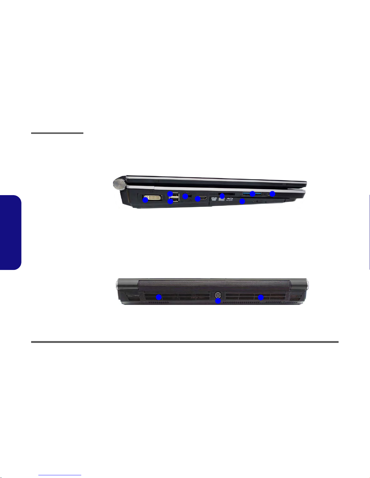
Interface
Four USB 2.0 Ports
(Note: One USB 2.0 port can supply power
when the system is off but still powered by the
AC/DC adapter, or powered by the battery with
a capacity level above 20% - see page 11.)
Two USB 3.0 Ports
One eSATA Port (USB 2.0 Port Combined)
One HDMI-Out Port
One DVI-Out Port
One S/PDIF Out Jack
One Headphone/Speaker-Out Jack
One Microphone-In Jack
One Line-In Jack
One Mini-IEEE1394a Port
One RJ-45 LAN
Jack
One DC-In Jack
Note: External 7.1CH Audio Output Supported
by Headphone, Microphone, Line-In and Sur-
round-Out Jacks

Introduction
System Specifications 1 - 3
1.Introduction
Slots
One ExpressCard/54(34) Slot
One Mini Card Slot for WLAN Module or
WLAN and Bluetooth Combo Module
Audio
High Definition Audio Compliant Interface
S/PDIF Digital Output
Five Speakers
One Sub Woofer
Built-In Microphone
THX TruStudio Pro
Environmental Spec
Temperature
Operating: 5°C - 35°C
Non-Operating: -20°C - 60°C
Relative Humidity
Operating: 20% - 80%
Non-Operating: 10% - 90%
Power
Full Range AC/DC Adapter
AC Input: 100 - 240V, 50 - 60Hz
DC Output: 19V, 11.57A (220W)
Removable 8-cell Smart Lithium-Ion Battery
Pack, 89.21WH
Dimensions & Weight
439mm (w) * 299mm (d) * 44mm - 65mm (h)
Around 5.6kg with 89.21WH Battery and ODD

Introduction
1 - 4 External Locator - Top View with LCD Panel Open
1.Introduction
External Locator - Top View with LCD Panel Open
Figure 1
Top View
1. Optional Built-In PC
Camera
2. LCD
3. Speakers
4. LED Status Indicators
5. Touch Sensor Instant
Keys
6. 8 * Gaming Keys
7. Keyboard
8. TouchPad and
Buttons
9. Fingerprint Reader
Module (optional)
10. LED Power
Indicators
2
1
7
8
9
5
6
4
3 3
10

Introduction
External Locator - Front & Right side Views 1 - 5
1.Introduction
External Locator - Front & Right side Views
Figure 2
Front Views
1. Speakers
2. LED Power
Indicators
Figure 3
Right Side Views
1. ExpressCard/54(34)
Slot
2. Headphone-In Jack
3. Microphone-In Jack
4. Line-In Jack
5. S/PDIF-Out Jack
6. Combined eSATA/
USB Port
7. USB 2.0 Port
8. Security Lock Slot
9. Power Button
2
1 1
3
245
6
1 7 8
9

Introduction
1 - 6 External Locator - Left Side & Rear View
1.Introduction
External Locator - Left Side & Rear View
Figure 4
Left Side View
1. DVI-Out Port
2. Powered USB 2.0
Port
3. USB 2.0 Ports
4. RJ-45 LAN Jack
5. HDMI-Out Port
6. Multi-in-1 Card
Reader
7. USB 3.0 Ports
8. Mini-IEEE 1394 Port
9. Optional Device
Drive Bay
1
2
3
459
67 8
Figure 5
Rear View
1. Fan Outlet
2. DC-In Jack
121

Introduction
External Locator - Bottom View 1 - 7
1.Introduction
External Locator - Bottom View
Figure 6
Bottom View
1. Sub Woofer
2. Fan Outlet/Intake
3. Component Bay
Cover
4. Battery
5. HDD Bay
Overheating
To prevent your com-
puter from overheating
make sure nothing
blocks the vent/fan in-
takes while the com-
puter is in use.
1
2
45
3
2 2
2 2 2

Disassembly
2 - 2 Overview
2.Disassembly
NOTE: All disassembly procedures assume that the system is turned OFF, and disconnected from any power supply (the
battery is removed too).
Maintenance Tools
The following tools are recommended when working on the notebook PC:
• M3 Philips-head screwdriver
• M2.5 Philips-head screwdriver (magnetized)
• M2 Philips-head screwdriver
• Small flat-head screwdriver
• Pair of needle-nose pliers
• Anti-static wrist-strap
Connections
Connections within the computer are one of four types:
Locking collar sockets for ribbon connectors To release these connectors, use a small flat-head screwdriver to
gently pry the locking collar away from its base. When replac-
ing the connection, make sure the connector is oriented in the
same way. The pin1 side is usually not indicated.
Pressure sockets for multi-wire connectors To release this connector type, grasp it at its head and gently
rock it from side to side as you pull it out. Do not pull on the
wires themselves. When replacing the connection, do not try to
force it. The socket only fits one way.
Pressure sockets for ribbon connectors To release these connectors, use a small pair of needle-nose pli-
ers to gently lift the connector away from its socket. When re-
placing the connection, make sure the connector is oriented in
the same way. The pin1 side is usually not indicated.
Board-to-board or multi-pin sockets To separate the boards, gently rock them from side to side as
you pull them apart. If the connection is very tight, use a small
flat-head screwdriver - use just enough force to start.

Disassembly
Overview 2 - 3
2.Disassembly
Maintenance Precautions
The following precautions are a reminder. To avoid personal injury or damage to the computer while performing a re-
moval and/or replacement job, take the following precautions:
1. Don't drop it. Perform your repairs and/or upgrades on a stable surface. If the computer falls, the case and other
components could be damaged.
2. Don't overheat it. Note the proximity of any heating elements. Keep the computer out of direct sunlight.
3. Avoid interference. Note the proximity of any high capacity transformers, electric motors, and other strong mag-
netic fields. These can hinder proper performance and damage components and/or data. You should also monitor
the position of magnetized tools (i.e. screwdrivers).
4. Keep it dry. This is an electrical appliance. If water or any other liquid gets into it, the computer could be badly
damaged.
5. Be careful with power. Avoid accidental shocks, discharges or explosions.
•Before removing or servicing any part from the computer, turn the computer off and detach any power supplies.
•When you want to unplug the power cord or any cable/wire, be sure to disconnect it by the plug head. Do not pull on the wire.
6. Peripherals – Turn off and detach any peripherals.
7. Beware of static discharge. ICs, such as the CPU and main support chips, are vulnerable to static electricity.
Before handling any part in the computer, discharge any static electricity inside the computer. When handling a
printed circuit board, do not use gloves or other materials which allow static electricity buildup. We suggest that
you use an anti-static wrist strap instead.
8. Beware of corrosion. As you perform your job, avoid touching any connector leads. Even the cleanest hands pro-
duce oils which can attract corrosive elements.
9. Keep your work environment clean. Tobacco smoke, dust or other air-born particulate matter is often attracted
to charged surfaces, reducing performance.
10. Keep track of the components. When removing or replacing any part, be careful not to leave small parts, such as
screws, loose inside the computer.
Cleaning
Do not apply cleaner directly to the computer, use a soft clean cloth.
Do not use volatile (petroleum distillates) or abrasive cleaners on any part of the computer.
Power Safety
Warning
Before you undertake
any upgrade proce-
dures, make sure that
you have turned off the
power, and discon-
nected all peripherals
and cables (including
telephone lines). It is
advisable to also re-
move your battery in
order to prevent acci-
dentally turning the
machine on.

Disassembly
Removing the Battery 2 - 5
2.Disassembly
Removing the Battery
If you are confident in undertaking upgrade procedures yourself, for safety reasons it is best to remove the battery.
1. Turn the computer off, and turn it over.
2. Slide the latch in the direction of the arrow.
3. Slide the latch in the direction of the arrow, and hold it in place.
4. Lift the battery up (Figure b) and out of the battery bay.
3. Battery
•3Screws
1
2
4
Figure 1
Battery Removal
a. Slide the latch in
the direction of the ar-
row and slide the latch
in the direction of the
arrow, and hold it in
place.
b. Release the battery.
c. Lift the battery out of the
bay as indicated.
1
2
a.
3
b.
12
c.
4
3

Disassembly
2 - 6 Removing the Optical (CD/DVD) Device
2.Disassembly
Removing the Optical (CD/DVD) Device
1. Turn off the computer, and turn it over and remove the battery (page 2 - 5).
2. Locate the component bay cover and remove screws - , and remove the bay cover .
3. Remove screw .
4. Push the optical device drive out of the bay and reverse the process to install the new device.
Figure 2
Optical Device
Removal
a. Remove the screws.
b. Remove the cover.
c. Remove the screw.
d. Push the optical device
out of the computer.
1
2
4
5
6
4. Hard Disk Bay Cover
6. Optical Device
•4Screws
a.
c.
b.
4
Blu-Ray Device Bezel Removal
Note that some Blu-Ray modules (e.g. Pio-
neer) have a small piece of mylar inserted in
the left side (as viewed front on) of the bezel
cover; in order to prevent the bezel cover of
the module from being removed accidentally.
If you need to replace the bezel cover, you will
need to use a screwdriver to ease out and re-
move the mylar before attempting to remove
the bezel cover. You will need to re-insert the
mylar when replacing the bezel cover.
1 2 3
5
d.
6

Disassembly
Removing the Hard Disk Drive 2 - 7
2.Disassembly
Removing the Hard Disk Drive
The hard disk drive is mounted in a removable case and can be taken out to accommodate other 2.5" SATA hard disk
drives with a height of 9.5mm (h). Follow your operating system’s installation instructions, and install all necessary driv-
ers and utilities (as outlined in Chapter 4 of the User’s Manual) when setting up a new hard disk.
Hard Disk Upgrade Process
1. Turn off the computer, and turn it over and remove the battery (page 2 - 5).
2. Locate the Hard disk bay cover and remove screws & .
3. Remove the bay cover .
Figure 3
HDD Assembly
Removal
a. Remove the screws.
b. Remove the cover
4. Hard disk Bay
Cover
•3Screws
1
3
4
2
a. b.
1
4
3

Disassembly
2 - 8 Removing the Hard Disk Drive
2.Disassembly
4. Remove screws - and pull the tab to disconnect the connector from hard disk assembly.
5. Lift the hard disk assembly out of the computer.
6. Remove screws - (depending on how many hard disks you have installed in the assembly).
7. Separate the hard disk board connector from the case .
8. Separate the hard disk(s) from the case.
9. Reverse the process to install a new hard disk(s).
Figure 4
HDD Assembly
Removal (cont’d.)
c. Remove the screws.
d. Lift the hard disk assem-
bly up out off the compu-
ter.
e. Remove the screws and
separate the HDD(s)
from the connector and
case.
10. Hard Disk Assembly
19. Hard Disk Case
20. Hard Disk Board
Connector
21. Hard Disks
•8Screws
5
8
9
10
11
18
20
19
21
6
78
9
12
d.
c.
20
5
e.
13
18
17 16
15
11
12
14
21
19
10
10

Disassembly
Removing the Hard Disk Drive 2 - 9
2.Disassembly
Removing the Hard Disk(s) in the Secondary HDD Bay
1. Turn off the computer, and turn it over and remove the battery and r.emove the optical device drive
2. The secondary hard disk bay is located under the optical device drive.
3. Remove screws - .
4. Remove the retaining pin and disconnect the hard disk cable .
5. Lift the hard disk assembly out of the compartment.
6. Remove the screws - to release the hard disk from the case .
7. Remove the cable .
8. Reverse the process to install any new hard disk(s).
9. Hard Disk Assembly
14. Hard Disk Case
15. Hard Disks Cable
16. Hard Disks
•10Screws
Figure 5
Secondary HDD
Assembly Removal
a. Remove the screws and
the retaining pin and dis-
connect the hard disk
cable.
b. Lift the hard disk assem-
bly out off the computer.
c. Remove the screws to
release the hard disk
from the case.
1
6
7
8
9
10
13
16
14
15
2
1
a.
3
4
b.
7
c.
10
15
5
6
8
7
9
12
11
13
16
c.
14

Disassembly
2 - 10 Removing the Keyboard
2.Disassembly
Removing the Keyboard
1. Turn off the computer, and turn it over and remove the battery (page 2 - 5).
2. Remove screws & from the bottom of the computer.
3. Turn the computer over, open the Lid/LCD, and carefully (a cable is connected to the underside of the LED cover
module) unsnap up the LED cover module from point on the right.
4. Lift up the LED cover module and disconnect the cable .
5. Remove screws - from the keyboard.
Figure 6
Keyboard
Removal
a. Remove the screws
from the bottom of
the computer.
b. Turn the computer
over, open the lid/
LCD and unsnap the
LED cover at point 3.
c. Lift the LED cover
module and discon-
nect the cable.
d. Remove the screws
from the keyboard.
4. LED cover module
•7Screws
1
2
4
3
4
5
6
10
c.
2
1
b.
3
5
6798
a.
10
d.
4
4

Disassembly
Removing the Keyboard 2 - 11
2.Disassembly
6. Carefully lift the keyboard up, being careful not to bend the keyboard ribbon cable.
7. Disconnect the keyboard ribbon cable from the locking collar socket .
8. Remove the keyboard .
9. Replace keyboard (make sure to reconnect the keyboard cable).
10. Snap the LED cover module down at the top fo the module at point & .
11. Push the LED cover module down on the left side at point , and then slide the module to the right (as illustrated)
and snap down to secure it in place.
12. Replace the screws on the bottom of the computer.
11
12
13
e.
11
12
13
f.
Keyboard Tabs
Re-Inserting the Keyboard
When re-inserting the keyboard
firstly align the four keyboard
tabs at the bottom (Figure 8e)
at the bottom of the keyboard
with the slots in the case.
Figure 7
Keyboard Removal
(cont’d.)
e. Disconnect the cable
from the locking collar.
f. Remove the keyboard.
g. Snap down the LED cov-
er.
h. Push the LED cover on
the left side at point
and the slide toward the
right to secure it in place.
17
13. Keyboard
14. LED cover module
14
15
16
17
g.
15 16
17
h.
14

Disassembly
2 - 12 Removing the System Memory (RAM) -1
2.Disassembly
Removing the System Memory (RAM) -1
The computer has three memory sockets for 204 pin Small Outline Dual In-line Memory Modules (SO-DIMM) DDR III
(DDR3) supporting 1066/1333 MHz. The main memory can be expanded up to 8GB. The total memory size is automat-
ically detected by the POST routine once you turn on your computer.
Removing the Primary System Memory (2 memory sockets)
1. Turn off the computer, and turn it over and remove the battery (page 2 - 5).
2. Locate the component bay cover and remove screws - .
3. Carefully (a fan and cable are attached to the under side of the cover) lift up the bay cover.
4. Carefully disconnect the fan cable in the order , &and remove the cover .
5. The primary memory sockets are visible at point
Figure 8
RAM-1 Module
Removal
a. Remove the screws.
b. Lift the cover and
disconnect the fan
cable.
6. component Bay
Cover
•4Screws
1
4
5
A
B
C
6
7
21
b.
34
5
a.
6
12
5
55
5
5
A
A
B
C
BC
7
Table of contents
Other XMG Laptop manuals