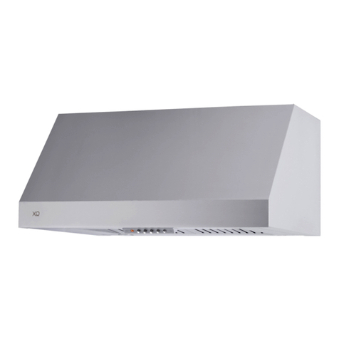
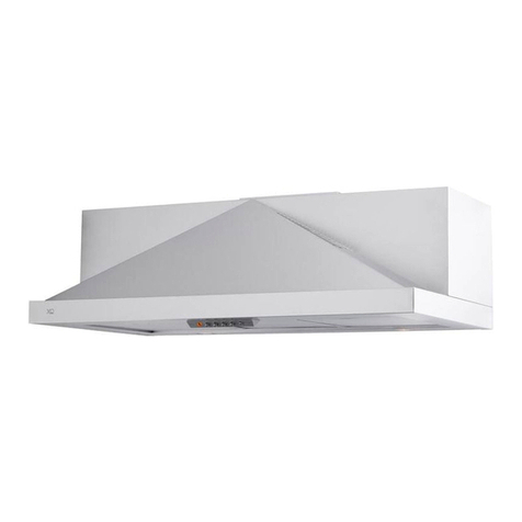
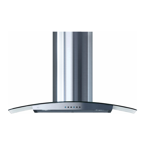
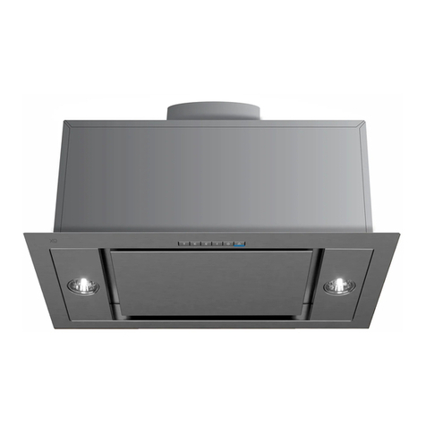
Xo XOC VISOR User manual

I worked really hard
on this manual - so
please read it...
XOC VISOR
MODELS XOC24SC, XOC30SC, XOC36SC


- 3 -
When buying any XO appliance
you can be confident you have chosen a
high quality, innovative and stylish product
from a company that cares about you!
If you require service or have questions,
there are 2 ways to contact our ventilation experts;
Online @ https://xoappliance.com/priority-service-for-your-xo-product/
Or by phone 973-403-8900
CONGRATULATIONS
on purchasing your XO.
Before you proceed, take just a
moment to register your XO at:
www.xoappliance.com/register-your-product/
REGISTRATION HELPS YOU BY -
Ensuring warranty coverage should you need service
Providing ownership verification for insurance purposes
Let’s XO notify you in the event of product changes or recalls.

- 4 -
It’s for your
own good...
Honest.
please read and follow
all safety instructions
where things are
GETTING READY
Safety and Precautions
Planning Ductwork
Install Examples
Dimensions
THE INSTALL
Mounting Height
Cut Out Dimensions
Installing
Electrical Connections
MAINTENANCE
Filters
Cleaning
Recirculation
Light Replacement
OPERATING
The Push Button Controls
CCC Make Up Air Conversion
PARTS & WARRANTY
23 - 24
25 - 26
5 - 11
12 - 20
21 - 22

- 5 -
safety first
IMPORTANT SAFETY INSTRUCTIONS
FOR RESIDENTIAL USE ONLY
READ AND SAVE THESE INSTRUCTIONS
PLEASE READ ENTIRE INSTRUCTIONS BEFORE PROCEEDING.
IMPORTANT: Save these Instructions for the Local Electrical Inspectors use.
INSTALLER: Please leave these Instructions with this unit for the owner.
OWNER: Please retain these instructions for future reference.
Take care when using cleaning agents or detergents.
Suitable for use in household cooking area.
WARNING - To reduce the risk of fire or electric shock, do not use this fan with any
Solid-State Speed Control Device.
CAUTION - To reduce risk of fire and to properly exhaust air, be sure to duct air out-
side – Do not vent exhaust air into spaces within walls or ceilings or into attics, crawl
spaces, or garages.
CAUTION - For Residential Kitchen ventilating use only. Do not use to exhaust haz-
ardous or explosive materials and vapors.
CAUTION - To avoid motor bearing damage and noisy and/or unbalanced impellers,
keep drywall spray, construction dust, etc. off power unit.
CAUTION - Please read specification label on product for further information and
requirements.
WARNING – TO REDUCE THE RISK OF FIRE, ELECTRIC SHOCK, OR INJURY TO PERSONS,
OBSERVE THE FOLLOWING:
A. Use this unit only in the manner intended by the manufacturer. If you have questions,
contact the manufacturer.
B. Before servicing or cleaning unit, switch power off at service panel and lock the ser-
vice disconnecting means to prevent power from being switched on accidentally.
When the service disconnecting means cannot be locked, securely fasten a promi-
nent warning device, such as a tag, to the service panel.
WARNING - TO REDUCE THE RISK OF A RANGE TOP GREASE FIRE:
A. Never leave surface units unattended at high settings. Boilovers cause smoking and

- 6 -
greasy spillovers that may ignite. Heat oils slowly on low or medium settings.
B. Always turn hood ON when cooking with high heat.
C. Clean ventilating fans frequently. Grease should not be allowed to accumulate on
fan or filter.
D. Use proper pan size. Always use cookware appropriate for the size of the surface
element.
E. Keep fan, filters and grease laden surface clean.
F. Use high range setting on range only when necessary. Heat oil slowly on low to me-
dium setting.
G. Don’t leave range unattended when cooking.
H. Always use cookware and utensils appropriate for the type and amount off food be-
ing prepared.
WARNING – TO REDUCE THE RISK OF INJURY TO PERSONS IN THE EVENT OF A RANGE
TOP GREASE FIRE, OBSERVE THE FOLLOWING:
A. SMOTHER FLAMES with a close-fitting lid, cookie sheet, or metal tray, then turn off
the burner. BE CAREFUL TO PREVENT BURNS. If the flames do not go out immediately,
EVACUATE AND CALL THE FIRE DEPARTMENT.
B. NEVER PICK UP A FLAMING PAN – You may be burned.
C. DO NOT USE WATER, including wet dishcloths or towels – a violent steam explosion
will result.
D. Use an extinguisher ONLY if:
1. You know you have a Class ABC extinguisher, and you already know how to operate it.
2. The fire is small and contained in the area where it started.
3. The fire department is being called.
4. You can fight the fire with your back to an exit.
aBased on “kitchen firesafety tips” published by NFPA.
Proper maintenance of the Range Hood will assure proper performance of the unit.
INSTALLATION INSTRUCTIONS
WARNING – TO REDUCE THE RISK OF FIRE, ELECTRIC SHOCK, OR INJURY TO PERSONS,
OBSERVE THE FOLLOWING:
A. Installation work and electrical wiring must be done by qualified person(s) in accord-
ance with all applicable codes and standards, including fire-rated construction.
B. Sufficient air is needed for proper combustion and exhausting of gases through the
flue (chimney) of fuel burning equipment to prevent back drafting. Follow the heat-
ing equipment manufacturer’s guideline and safety standards such as those pub-
lished by the National Fire Protection Association (NFPA), and the American Society
for Heating, Refrigeration and Air Conditioning Engineers (ASHRAE), and the local

- 7 -
code authorities.
C. When cutting or drilling into wall or ceiling, do not damage electrical wiring and
other hidden utilities.
D. Ducted fans must always be vented to the outdoors.
E. This unit must be grounded.
WARNING - TO REDUCE THE RISK OF FIRE, USE ONLY METAL DUCTWORK.
WARNING - UNDER CERTAIN CIRCUMSTANCES DOMESTIC APPLIANCES MAY BE
DANGEROUS.
A. Do not check filters with hood working.
B. Do not touch the lamps after a prolonged use of the appliance.
C. No food must be cooked flambè underneath the hood.
D. The use of an unprotected flame is dangerous for the filters and could cause fires.
E. Watch constantly while frying food in order to avoid cooking oil flare ups.
F. Before performing any maintenance operation, disconnect the hood from the
electrical service.
The manufacturers will not accept any responsibility for possible damages, because
of failure to observe the above instructions.

- 8 -
THIS HOOD IS DESIGNED TO USE A 6” ROUND DUCT -
IT MAY BE TRANSITIONED TO A 3-1/4” X 10” RECTANGULAR DUCT
NEVER REDUCE DUCT SIZE. UNDERSIZED DUCTING SEVERELY RESTRICTS AIR
FLOW AND HARMS PERFORMANCE.
(Example: the area of a 6” Duct is more than TWICE that of a 4” Duct)
KEEP DUCT RUNS AS SHORT AND STRAIGHT AS POSSIBLE.
AVOID USING FLEXIBLE METAL DUCTING IF RUN IS LONGER THAN 6’.
NEVER USE PLASTIC DUCTING.
USE SMOOTH BORE METAL DUCTING.
MINIMIZE THE NUMBER OF FITTINGS (see chart).
WHEN YOU MUST USE FITTINGS, TRY TO SEPARATE THEM WITH SECTIONS OF
3’ OR MORE OF STRAIGHT DUCT.
ALWAYS FOLLOW THE MANUFACTURER’S GUIDELINES FOR THE COOKING
EQUIPMENT YOU ARE VENTING.
IF MAKE UP AIR CONTROL DAMPERS ARE REQUIRED, POSITION THE SENSOR
IN A STRAIGHT RUN OF DUCT IDEALLY WITH 3’ OF STRAIGHT DUCT BETWEEN
EACH SIDE OF THE SENSOR AND A DUCT FITTING. REMEMBER TO INCLUDE
POWER AND CONTROL WIRING FOR THIS IN YOUR PLANS.
ADHERE TO ALL LOCAL BUILDING CODES AND ORDINANCES.
USE THE WORKSHEET THAT FOLLOWS TO HELP CALCULATE THE
TOTAL EQUIVILENT FEET OF YOUR DUCT RUN.
TOTAL EQUIVILENT FEET SHOULD BE LESS THAN 100’.
a few simple rules to plan your
ductwork
1
1
12
7
14
8
33
2
4
24
24
33

- 9 -
1
1
12
7
14
8
33
2
4
24
24
33
CAUSING AIR TO CHANGE DIRECTION CAUSES TURBULENCE AND RESTRICTS FLOW IN
A SYSTEM.
IF USING FLEXIBLE METAL DUCT - INCREASE ALL MULTIPLIERS BY 50% (12 BECOMES
18 - ETC.)
THIS EASY TO USE WORKSHEET IS FOR 600 CFM OR LESS.
UNDER “QTY USED” ENTER HOW OF EACH SECTION YOU WILL BE USING.
IN THE FIRST TWO ROWS - ENTER HOW MANY FEET OF EACH TYPE OF STRAIGHT DUCT
YOU WILL BE USING (I.E. FOR 20 FT ENTER 20, FOR 30FT ENTER 30).
ENTER THE NUMBER OF EACH TYPE OF TURN YOU ARE USING AND THE TYPE OF END CAP.
MULTIPLY ACROSS EACH ROW THE “MULTIPLIER” x “QTY USED” TO GET THE EQUIVALENT
FEET FOR THOSE COMPONENTS.
ADD UP ALL THE VALUES IN THE “EQUIVALENT FEET” COLUMN.
DUCT PIECE DESCRIPTION MULTIPLIER QTY USED EQUIVALENT
FEET
1’ of 6” Round Duct
1’ of 3 1/4“ x 10” Rect. Duct
6” 90 Degree Elbow
6” 45 Degree Elbow
3 1/4” x 10” 90 Degree
3 1/4” x 10” 45 Degree
3 1/4” x 10” Side 90 Degree
3 1/4” x 10” x 6” Round
3 1/4” x 10” x 6” 90 Degree
6” Round Wall Cap w Damper
3 1/4” x 10” Wall Cap w Damper
6” Round Roof Cap
TOTAL EQUIVALENT FEET SHOULD BE LESS THAN 100
estimating total equivalent feet in
a duct

- 10 -
VENTEDRECIRCULATION
WALL EXHAUST ROOF EXHAUST
SOFFIT EXHAUST
RECIRCULATION EXHAUST MUST BE RETURNED TO THE
SPACE
typical installation examples
1-3/16"
16-15/16"
11-1/16"
9"
1-9/16"
B
12-1/8"
min 0 - 0/16" - max 1 - 4/16"
L
A
C
11-1/16"
Ø 6"
3-13/16"
D
1-11/16"
2-9/16"
5-1/8"
1-11/16"
min 0 - 0/16" - max 1 - /4"
CABINET TOP EXHAUST

- 11 -
1-3/16"
16-15/16"
11-1/16"
9"
1-9/16"
B
12-1/8"
min 0 - 0/16" - max 1 - 4/16"
L
A
C
11-1/16"
Ø 6"
3-13/16"
D
1-11/16"
2-9/16"
5-1/8"
1-11/16"
min 0 - 0/16" - max 1 - /4"
Front of hood Side of hood
Top of hood
dimensions
MODEL A B C D
XOC24SC 24” 18-5/8” 19-11/16” 1-15/16”
XOC30SC 30” 18-5/8” 19-11/16” 5-1/8”
XOC36SC 36” 30-7/16” 31-1/2” 1-15/16”

- 12 -
27”to32”
RECOMMENDED
MOUNTING HEIGHT
ABOVE GAS AND
ELECTRIC COOKTOPS
highs and lows
All range hoods have a recommended range of installation height over the cooking
surface.
It is important to install the hood at the proper mounting height. Hoods mounted too
low could result in heat damage and fire hazard; while hoods mounted too high will
be hard to reach and will lose its performance and efficiency.

- 13 -
27”to32”
WIDTH
11-3/16"
To install the hood into a custom canopy or cabinet, refer to the cutout dimensions
above for your particular model. Gap around the unit should be minimized (~ 1/16”)
to ensure a snug fit.
the cut out
MODEL
XOC24SC
XOC30SC
WIDTH
19-3/4”
19-3/4”
XOC36SC 31-9/16”
NOTE:
This product can be installed in 3 different ways, depending on the model and on
your requirements:
1- installation of the hood on the lower part of the wall unit.
2- installation of the hood on the lower part of the wall unit on a divider support.
3- Installation of the hood on the lower part of the wall unit only for 30”.

- 14 -
24" - 36" - 30"
34
2
1
2
A
B
2
M
F
Min 0-1/2"
Max 1/016"
F
installation “1”
FIXING THE HOOD TO THE LOWER PART OF THE WALL CABINET:
1- Position template B on the wall unit, bearing in mind the measurements and the mi-
nimum distance from the hob.
- Mark the references to fix brackets A to the wall unit, as indicated in figure .
2- Make sure the thickness of the wall unit is within the parameters indicated in figure
- step 2.
3- Build the hood in the wall unit and make sure the 2 side springs F are connected cor-
rectly. Fasten the hood to the wall unit using the screwdriver and the relative screws M
and tighten until the device is firmly against the wall unit ( - step 2).
4- Remove pin Y from bracket A. Then place the insert X on the slot of the bracket A, as
indicated in figure - step 3.
- Match the C screws with the L wascher and fix the A bracket to the cabinet as indicated
in figure - step 3.1. Pay attention not to completely tighten screws C before the bra-

- 15 -
24" - 36" - 30"
34
2
1
2
A
B
2
M
F
Min 0-1/2"
Max 1/016"
F
3Y
A
X
3.2
3.3
3.2
3.3
4
DD
5
P
P
L
Y
D
X
L
C
L
3.1
C
cket firmly reaches the wall unit ( - step 3.2). After any adjusting, tighten the bracket to
the body ( - step 3.3).
- Fasten screw D to the wall unit as indicated in figure - step 4.
- Once you have fastened the hood to the wall unit, adjust the spacer L, with the screws
P, to make the device line up with the rear wall unit (figure - step 5).
IMPORTANT - The range hood must be secured to wall studs or use drywall
anchors capable of supporting 75 lbs.

- 16 -
2
1
6
6
24" - 36"
19-11/16" (24")
31-1/2" (36")
11-1/16"
Ø 6"
3-13/16"
1-15/16" (24"-36")
1-11/16"
7-11/16"
1-11/16" 19-11/16" (30")
5-1/8" (30")
Ø 6"
3-13/16" 1-11/16"
1-11/16"
11-1/16"
7-11/16"
30"
6
D
INSTALLATION OF THE HOOD ON THE LOWER PART OF THE WALL UNIT ON THE
DIVIDING PANEL.
Follow the steps below:
1 -Check the measurements and the minimum distance from the hob, before installing
the hood on the dividing panel.
3- Make sure the thickness of the wall unit is within the parameters indicated in figure
- step 2.
4- Build the hood in the wall unit and make sure the 2 side springs F are connected
correctly. Fasten the hood to the wall unit using the screwdriver and the relative screws
M and tighten until the device is firmly against the wall unit (figure - step 2).
5- Fasten the hood to the upper wall unit as indicated in figure - step 6.
- Once you have fastened the hood to the wall unit, adjust the spacer L, with screws P, to
make the device line up with the rear wall unit (figure - step 5).
IMPORTANT - The range hood must be secured to wall studs or use drywall
anchors capable of supporting 75 lbs.
installation “2”

- 17 -
2
1
6
6
24" - 36"
19-11/16" (24")
31-1/2" (36")
11-1/16"
Ø 6"
3-13/16"
1-15/16" (24"-36")
1-11/16"
7-11/16"
1-11/16" 19-11/16" (30")
5-1/8" (30")
Ø 6"
3-13/16" 1-11/16"
1-11/16"
11-1/16"
7-11/16"
30"
6
D

- 18 -
30"
34
7
1
GD
E
B
E
E
G
D
1
2
3
A
30"
E
G
E
4
5
installation “3”

- 19 -
30"
34
7
1
GD
E
B
E
E
G
D
1
2
3
A
30"
E
G
E
4
5
INSTALLATION OF THE HOOD ONTHE LOWER PART OFTHEWALL UNIT ONLY FOR 30".
This model includes side installation to the wall unit by using 2 brackets B (figure besides
steps 3-4, indicated in figure ).
1- Position template B on the wall unit, bearing in mind the measurements and the
minimum distance from the hob.
- Mark the references to fix brackets A to the wall unit, as indicated in figure .
2 - Position the second template E on the side of the wall unit and make sure that the line
matches up with that traced in figure - step 1.
3 - Mark and drill the 4 fixing holes (figure - step 2).
- Fasten the 2 brackets G to the wall unit using the 4 screws D (figure - step 3).
- Fasten the hood to bracket G using the 4 screws E (figure - step 4-5).
4- Remove pin Y from bracket A. Then place the insert X on the slot of the bracket A, as
indicated in figure - step 3.
- Match the C screws with the L wascher and fix the A bracket to the cabinet as indicated
in figure - step 3.1. Pay attention not to completely tighten screws C before the bracket
firmly reaches the wall unit (figure - step 3.2). After any adjusting, tighten the bracket
to the body (figure - step 3.3).
- Fasten screw D to the wall unit as indicated in figure - step 4.
- Once you have fastened the hood to the wall unit, adjust the spacer L, with screws P, to
make the device line up the rear wall unit (figure - step 5).
IMPORTANT - The range hood must be secured to wall studs or use drywall
anchors capable of supporting 75 lbs.

- 20 -
1. Route the power cord to the junction box inside the hood.
2. Using listed conduit fittings and connectors, connect the power supply to the box and each
line to the appropriate wire following this color convention:
BLACK = HOT LEG
WHITE = NEUTRAL
GREEN/YELLOW = GROUND
Polarity must be observed.
Unit must be properly grounded.
Use a double throw disconnect switch.
3. Replace the box cover
4. Replace the Anti-grease filters.
All wiring must be in compliance with national electrical code, ANSI/NFPA 70-1999 and all
local codes and regulations.
electrical connection
This manual suits for next models
3
Table of contents
Languages:
Other Xo Ventilation Hood manuals
Popular Ventilation Hood manuals by other brands

Electrolux Professional
Electrolux Professional HOBT11 installation manual

Schweigen
Schweigen UM1170-9BS installation guide

KOBE
KOBE CH00 Series Installation instructions and operation manual

Electrolux
Electrolux EFP60240OW user manual

Electrolux
Electrolux EFC 9441 Operating and installation instructions

THERMEx
THERMEx Integrata Lift manual