3
1General Information
Read all these instructions & warnings fully before
commencing installation.
These installation and operating instructions must
be observed during installation, operation, service
and maintenance. This MVHR should only be in-
stalled and repaired by a qualified service techni-
cian. Improper repairs may expose the user to con-
siderable danger. Under current regulations, the
installation and operating instructions must be ac-
cessible at all times and must be handed to the
technician for reference whenever work is being
done on the MVHR. We would therefore ask that
upon moving out of these premises, you pass the
instructions on to the next tenant/owner. Should
there be any visible damage the MVHR must not be
connected. In this case, it is imperative that you
contact your supplier. Only use original spares in
order to avoid secondary damage. Please ensure
that all packaging materials are disposed of prop-
erly in accordance with current environmental re-
quirements.
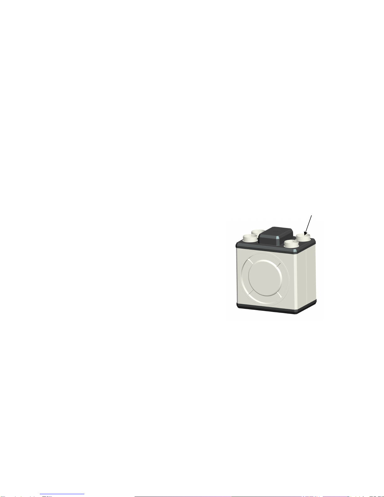
2Components and Materials of Construction
The MVHR comprises of the following main compo-
nents:
Outer Panels:
PE plastic, white
PS plastic, black
Maintenance access cover:
PS plastic
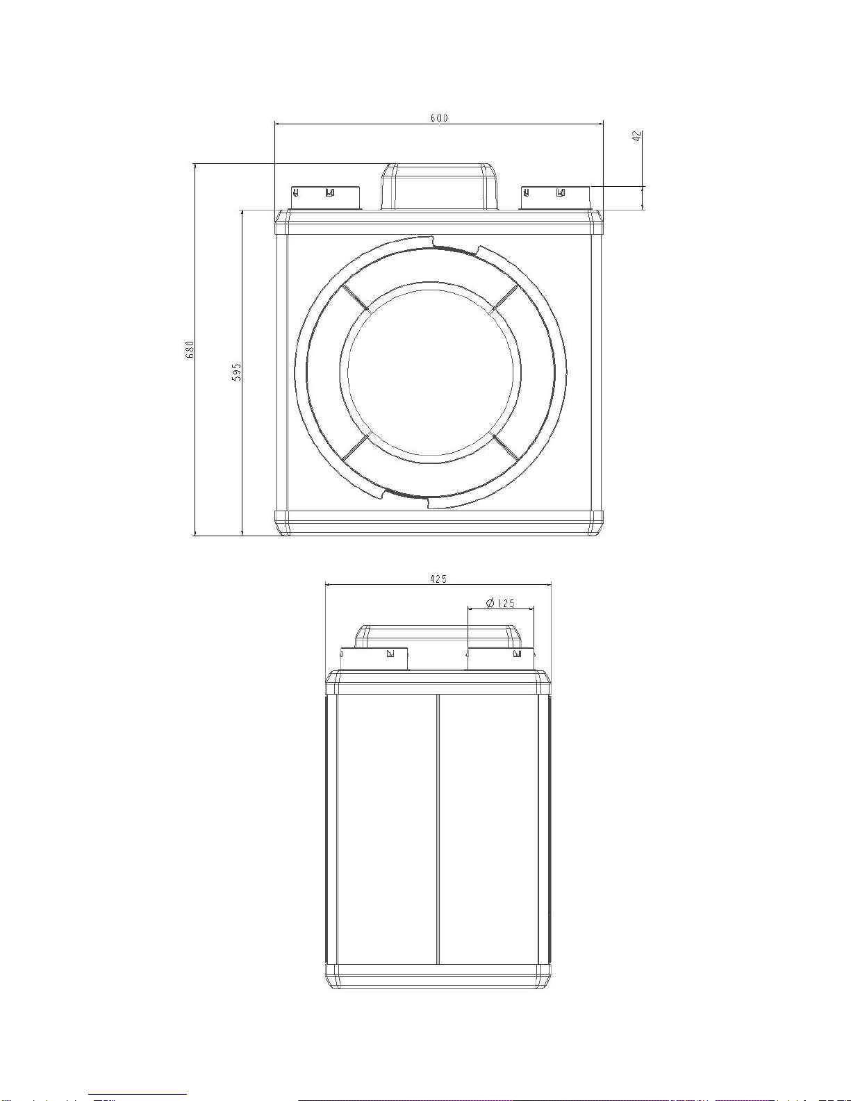
Ducting spigots, Ø125mm:
PP plastic, light grey
Internal air paths / casing:
EPP, black
Filters:
G4 fitted as standard. External filter box F5 or F7
available as special accessory
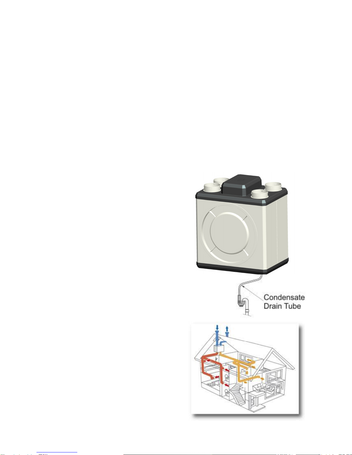
Heat exchanger:
The heat exchanger is made from fully recyclable
PS plastic. The heat exchanger integrated into the
MVHR is based on the counter flow principle with
triangular air ducts for supply and exhaust air.
Fans:
Energy-saving EC DC fans with optimal efficiency.
3Regulations and Safety Instructions
The Xcell150 MVHRs are tested in accordance with
the low-voltage directive 2006/95/EC and EMC
directive 2004/108/EC.
This appliance is not intended for use by persons
(including children and the infirm) with reduced
physical, sensory or mental capabilities, or lack of
experience and knowledge, unless they have been
given supervision or instruction concerning use of
the appliance by a person responsible for their
safety.
Ensure that all relevant safety precautions (correct
eye protection and protective clothing etc) are taken
when installing, operating and maintaining this
MVHR. Observe the safety regulations and warn-
ings contained in this manual at all times. Failure to
do so may result in damage to the unit or personal
injury.
This MVHR is intended for connection to fixed wir-
ing.A means for disconnection must be incorpo-
rated in the fixed wiring. Installations and wiring
must conform to current IEE Regulations (UK), local
or appropriate regulations (other countries). All
installations must be supervised by a qualified elec-
trician. It is the installer’s responsibility to ensure
that the appropriate building codes of practice are
adhered to.
This MVHR must not be installed near to sources of
direct heat such as cookers/grills or where ambient
temperatures may exceed 50•C.
When the MVHR is installed in a room containing a
fuel burning appliance, precautions must be taken
to avoid the backflow of gases into the room from
the open flue of the fuel burning appliance.
The instructions on periodic cleaning and/or chang-
ing of the filters, the air inlet/outlet valves and the
air inlet/outlet grilles must be strictly observed.
The unit may only be connected to a 220-240V AC
power supply.
The following applications / installations are
prohibited:
The use of excessive fat-contaminated exhaust
air, extracting explosive gases, extracting parti-
cle-contaminated air, extracting adhesive par-
ticulate matter.
Installing the MVHR outdoors
Connecting extractor hoods in the ventilation
system
Servicing of the MVHR may only be carried out by a
qualified service technician. Contact details for
authorised servicing by Xpelair approved techni-
cians can be found on the back of this booklet.