Xpelair DX100B User manual

DX100BR
(92997AW)
DX100BS
(93017AW)
DX100BTR
(92998AW)
DX100BTS
(93018AW)
DX100BHTR
(92999AW)
DX100BHTS
(93019AW)
DX100BHPTR
(93000AW)
DX100BHPTS
(93020AW)
DX100BPR
(93001AW)
DX100BPS
(93002AW)
Xpelair Simply Silent
DX100B
™
Installation and Maintenance Instructions
English
َُِ َ

• Doreadtheentireinstructionleaetbeforecommencinginstallation.
• Doinstalleachfanwithameansfordisconnectioninallpolesinthexedwiring.
• Domakesurethemainssupplyisswitchedobeforeattemptingtomakeelectrical
connectionsorcarryoutanymaintenanceorcleaning.
• Pleaseleavethisleaetwiththefanforthebenetoftheuser.
Installation and Maintenance Instructions
English
Standard Timer Humidistat,Timer
Humidistat,Pull
Cord,Timer PullCord
DX100BR
(92997AW)
DX100BS
(93017AW)
DX100BTR
(92998AW)
DX100BTS
(93018AW)
DX100BHTR
(92999AW)
DX100BHTS
(93019AW)
DX100BHPTR
(93000AW)
DX100BHPTS
(93020AW)
DX100BPR
(93001AW)
DX100BPS
(93002AW)

Thisapplianceisintendedfor
connectiontoxedwiring.Checkthat
theelectricalratingshownoneach
fanmatchesthemainssupply.
THE APPLIANCE IS DOUBLE INSULATED
AND DOES NOT REQUIRE AN EARTH
CONNECTION.
Allinstallationsmustbesupervisedbya
qualiedelectrician.Installationsandwiringmust
conformtocurrentIEERegulations(UK),localor
appropriateregulations(othercountries).
This appliance can be used
by children aged from 8 years
and above and persons with
reduced physical, sensory
capabilities or lack of
experience and knowledge
if they have been given
supervision or instruction
concerning the use of the
appliance in a safe way and
understand the hazards
involved. Children shall not
play with the appliance.
Cleaning and maintenance
of the appliance shall not be
made by children.
AllXpelairSimplySilent™DX100BAC
fanshavethefollowingfeatures:
• Twospeedextraction
(Selectableatinstallation)
DX100BR/DX100BS - Operatethefanusingan
on/oswitch(notsupplied).
DX100BTR/DX100BTS* - Built-intimer
operatesfanforapresetdelayfrom30
secondsto30minutes.
DX100BHTR/DX100BHTS* - Operateswhen
triggeredautomaticallybytheintegralhumiditysensor,
orbyusinganexternalon/oswitch(notsupplied).
In automatic mode: thebuilt-intimerautomatically
operatesthefanforapre-setdelaytimefrom30
secondsto30minutesoncehumiditydropsbelow
thepre-setRelativeHumidity(RH)value.
External operation:Whenswitchedousingthe
externalon/oswitchthefancontinuestorunfor
thepresetdelayfrom30secondsto30minutes.
DX100BHPTR/DX100BHPTS* - Operateswhen
triggeredautomaticallybytheintegralhumidity
sensor,byusinganexternalon/oswitch(not
supplied),orbyusingtheintegralpullcordswitch.
In automatic mode: Thebuiltintimerautomatically
operatesthefanforthepre-setdelaytimefrom30
secondsto30minutesoncehumiditydropsbelow
thepre-setRelativeHumidity(RH)value.
External operation:Whenswitchedousing
eithertheexternalon/oswitchortheintegral
pullcordswitchthefancontinuestorunforthe
pre-setdelayfrom30secondsto30minutes.
DX100BPR/DX100BPS - Operatethefanusing
anintegralpull-cord.
* Factory settings: Timer 15 minutes, RH 75%
Where to locate the fan.
• Locateitashighaspossible.
• Atleast110mmfromtheedgesof
themountingsurfacetothecentre
ofthehole.
• Asfarawayaspossiblefromandoppositeto
themainsourceofairreplacementtoensure
airowacrosstheroom(e.g.oppositethe
internaldoorway).
• Nearthesourceofsteamorodours.
• Notwhereambienttemperatures
are likely to exceed 50°C.
• Ifinstalledinakitchen
fans must not be mounted
immediately above a cooker
hob, or eye level grill.
• Ifinstallinginaroomcontainingafuel
burning device which has a non-balanced
flue, it is the installer’s responsibility to
ensure that there is enough replacement air
to prevent fumes being drawn down the flue
when the fan is operating up to maximum
extract. Refer to Building Regulations for
specific requirements.
• Exhaustairmustnotbedischargedinto
a flue used for exhausting of fumes from
appliances supplied with energy other than
electric. Requirements of all authorities
concerned must be observed for exhaust air
discharge and intake flow rates.
• Notsuitableforuseinpossiblechemical
corrosive atmospheres.
Installation
What the installer will need.
• 3mmelectrician’sscrewdriver
andNo.1or2Pozidrive
screwdrivers.
English

Overall Dimensions (mm)
Back plate
fixing positions
A
Front Cover Removal
B
DEPRESSCOVERLATCHWITHTOOL&REMOVECOVERCOMPLETE
English
IMPORTANT – PLEASE READ
Adjusting the humidity setting
Adjusting the run on timer setting
Fanswitcheson
atlowerlevelof
condensation
(anti-clockwise)
MORESENTITIVE
(RH=50%)
Fanrunsonfora
shortertimewhen
theexternalswitch
isturnedo
Fandoesnot
switchonuntil
higherlevelof
condensation
(clockwise)
LESSSENTITIVE
(RH=95%)
Fanrunsonfora
longertimewhen
theexternalswitch
isturnedo
Factory settings:
Timer15minutes,RH75%
Maximum30minutesMinimum30seconds
C

English
Wiring and setting up
D1
DX100BR / DX100BS
DX11BPR / DX100BPS
DX100BTR / DX100BTS
SEEDETAILB
SEEDETAILC
CUSTOMER
CONNECTION
TERMINAL
DETAIL C
SCALE 2.000
OVER-RUN
TIMER
DETAIL B
SCALE 2.000
SETJUMPERTOREQUIRED
POSITIONFORSPEEDSETTING
HIGH
SPEED
LOW
SPEED
SEEDETAILA
CUSTOMER
CONNECTION
TERMINAL
SETJUMPERTOREQUIRED
POSITIONFORSPEEDSETTING
DETAIL A
SCALE 2.000
HIGH
SPEED
LOW
SPEED
LEVELLINE
LEVELLINE

English
Wiring and setting up
D2
DX100BHTR / DX100BHTS
DX100BHPTR / DX100BHPTS
SEEDETAILF
SEEDETAILG
CUSTOMER
CONNECTION
TERMINAL
SEEDETAILD
SEEDETAILE
CUSTOMER
CONNECTION
TERMINAL
DETAIL F
SCALE 2.000
SETJUMPERTOREQUIRED
POSITIONFORSPEEDSETTING
HIGH
SPEED
LOW
SPEED
DETAIL D
SCALE 2.000
OVER-RUN
TIMER
HUMIDISTAT
DETAIL E
SCALE 2.000
SETJUMPERTOREQUIRED
POSITIONFORSPEEDSETTING
HIGH
SPEED
LOW
SPEED
DETAIL G
SCALE 2.000
OVER-RUN
TIMER
HUMIDISTAT
LEVELLINE
LEVELLINE

English
If wall mounting the fan, you will also need:
• A100mmdiameterpreparedhole.
• ASimplySilentWallKit:
SSWKWR(92991AW)–Round/White
SSWKWS(92992AW)–Square/White
SSWKBR(92993AB)–Round/Brown
SSWKBS(92994AB)–Square/Brown
If ceiling mounting the fan, you will also need:
• A100mmdiameterpreparedhole.
• A100mmdiameterpreparedholeforthe
externalgrille(notsupplied),ideallypositioned
toallowcondensationtorunawayfromtherst
bendintheduct,towardstheexternalgrille.
• Appropriateancillariesfortermination.These
itemsareavailablefromXpelair:
1.3mexibleductingRef:89663AA.If
theductpassesthroughacoldspaceuse
insulatedductref:89847AA.
2.SotGrilleRef:89742AW.
If window mounting the fan, you will also need:
• SSWIN–SimplySilentWindowKit.
Ref:92996AA
Installing the isolating switch
and cables.
Ameansfordisconnectioninallpoles
mustbeincorporatedinthexedwiring
inaccordancewithwiringregulations
• Ifmetalswitchboxesareused,earthing
regulations must be followed.
• Thecross-sectionalareaofthesupplycord
usedshouldberangedfrom1-1.5mm².
• DX100BR/DX100BS/DX100BPR/
DX100BPS–2core.
• DX100BTR/DX100BTS/DX100BHTR*
/DX100BHTS*/DX100BHPTR*/
DX100BHPTS*–3core.
*Ifwiringtoremoteswitch.
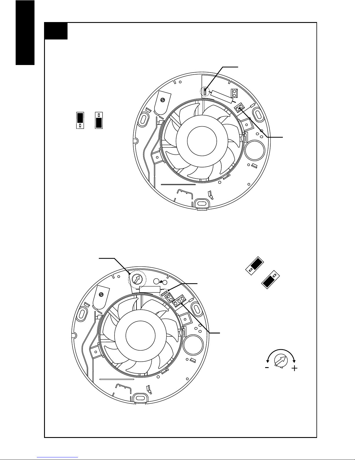
1. Check that the electrical rating shown inside
the back-plate matches your mains supply.
2. Check there are no buried pipes or cables
e.g. electricity, gas, water behind the switch
location (in the wall or above the ceiling). If in
doubt, seek professional advice.
3. Isolate the mains supply.
4.Layinthecablefromtheisolatingswitchtothe
fanlocationviatheon/oswitch(ifrequired).
5.Layinthecablefromtheisolatingswitchto
thepointofconnectiontothemainssupply.
Warning: Do not make any
connections to the electrical supply
at this stage.
6.Installtheisolatingswitchandon/oswitch
(ifrequired).
7.Makeallconnectionswithintheisolating
switchandtheon/oswitch(ifrequired).
Wet Rooms: On/Off switch must
be situated so that it cannot be
touched by persons making use of
the bath or shower.
For Australia Only – DX100BR / DX100BS /
DX100BPR / DX100BPS Connectiontothe
supplycanbemadebyaexible2-corecable
completewith3pinplugforinsertionintoan
approved10AGPOordirectlywiredthroughan
approved10Awallmountedsurfaceswitchwith
atleast3mmclearancebetweencontacts.
For Australia Only –DX100BTR / DX100BTS /
DX100BHTR / DX100BHTS / DX100BHPTR /
DX100BHPTS Thesemodelsarepermanently
connectedtothesupplyandoperationis
controlledbyaremoteswitch.Theyshould
bedirectlywiredtothesupplythroughan
approved10Awallmountedsurfaceswitch
withatleast3mmclearancebetweencontacts.
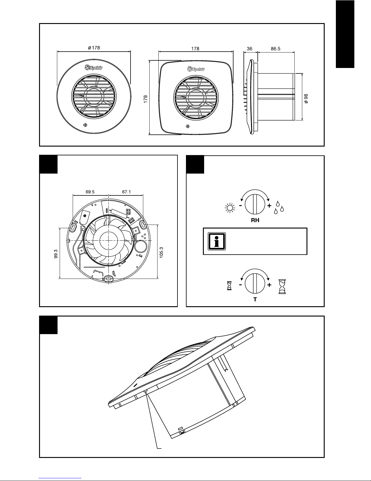
Preparing the Fan for installation.
1. Removethefrontcoverbydepressingthe
latchontheundersideofthecoverand
pullingothefrontcoverfromthebottom
(SeeFigureB).
If working above ground floor
level, safety precautions must be
observed.
Mark the position of the back-plate
2. Holdtheback-platesothatthelevelline
markedonitisorientatedhorizontally.
3. Carefullyinsertthefantubeintothewallduct.
4. Markonthewallthepositionsofthexing
holesintheback-plate.
5. Removethebackplatefromtheducting.
6. Drillscrewholesinthesepositionsifnecessary,
andtwallplugsandscrewsasrequired.
If installing in a ceiling, appropriate
termination ancillaries are required.
Follow instructions provided.
Mount the back-plate.
7. Feedthemainscablethroughthecable
entryholeinthebackplatetotheterminals.
8. Insertthefantubeoftheback-plateintothe
wallduct/ceilingasbefore.
9. Fastentheback-platetothewall/ceiling
usingappropriatefasteners.SeegureA.
10.Ifusingscrews,donotovertighten.

Wire the electrical connections.
11.Makesurethemainssupplyisisolated.
Switchothemainselectricalsupplyand
removefuses.
12.Feedthecabletotheterminalblock.Wire
thefanasshowninFigureEusingthe
diagramappropriatetothefanmodel.
13.Connectthecablefromtheisolatingswitch
totheelectricalsupplywiring.
Fan Settings
SPEED SETTING
Thefansarefactorysettolowspeed,buthave
twospeedsettingsfordierentapplications.
Selecteitherhighorlowspeedbyconnecting
thejumperbetweenthecentreandhighorlow
speedpinonthejumper(seeFigureD1&D2).
DX100BTR / DX100BTS Only.
• Toadjusttheover-runperiodturnthecontrol
(T)clockwisetoincreaseandanti-clockwise
todecrease–seeFigureD1.
DX100BHTR / DX100BHTS / DX100BHPTR /
DX100BHPTS only – see figures C and D.
• Thepre-sethumidityoperationisfactoryset
atapproximately75%RelativeHumidity(RH),
butcanbeadjustedbetween65%and85%
RHbycontrolH.
• Theover-runtimerisfactorysetat15minutes
butcanbeadjustedfrom30secondsto30
minutesbycontrolT.
• TurnthecontrolsclockwisetoincreaseRHor
timeandanti-clockwisetodecrease.
English
DX100BR/DX100BS
DX100BPR/DX100BPS
DX100BTR/DX100BTS
DX100BHTR/DX100BHTS
DX100BHPTR/DX100BHPTS
E
FAN
TERMINALS
FAN
TERMINALS
FAN
TERMINALS
DOUBLEPOLE
ISOLATINGSWITCH
DOUBLEPOLE
ISOLATINGSWITCH
DOUBLEPOLE
ISOLATINGSWITCH
ON/OFF
SWITCH
(OPTIONAL)
ON/OFF
SWITCH
(REQUIRED)
LAMP
(IFREQUIRED)
LAMP
(IFREQUIRED)
FUSE
FUSE
FUSE
For fixed wiring circuits the protective fuse
for the appliance must not exceed 5A.

English
Using the fan
DX100BR / DX100BS Only
• Operatethefanusingtheon/oswitch(not
supplied).Repeattoswitcho.
DX100BTR / DX100BTS Only
• Operatethefanusinganon/oswitch(not
supplied).Note–thefanmaytakeupto10
secondstoturnononcetheswitchhasbeen
operated.Whentheswitchisturnedo,
thefancontinuestooperateforthesettime
delay.Toadjusttheover-runperiod,turnthe
control“T”clockwisetoincreaseandanti-
clockwisetodecrease–seeFigureD1.
DX100BHTR / DX100BHTS Only
• Automatic mode-Thefanautomatically
adjuststoslowchangesinnaturalhumidity
levelswithoutoperatingthefan.Ifthehumidity
levelsincreaseatarateslowerthan5%RH
in5minutes,uptothepre-sethumiditylevel,
thefanwillnotbetriggeredbyhumidity.This
istopreventnuisancetriggeringofthefan.If
humiditylevelsincreasequickerthan5%RH
in5minutesthefanwilloperate.Whenrelative
humiditydropsthefancontinuestooperatefor
theadjustabletimedelay.
• External operation-Usetheexternalon/o
switch.Whenthefanisswitchedo,thefan
continuestooperatefortheadjustabletime
delaythengoesintoautomaticmode.
DX100BHPTR / DX100BHPTS Only
• Automatic mode-Thefanautomatically
adjuststoslowchangesinnaturalhumidity
levelswithoutoperatingthefan.Ifthehumidity
levelsincreaseatarateslowerthan5%RH
in5minutes,uptothepre-sethumiditylevel,
thefanwillnotbetriggeredbyhumidity.This
istopreventnuisancetriggeringofthefan.If
humiditylevelsincreasequickerthan5%RH
in5minutesthefanwilloperate.Whenrelative
humiditydropsthefancontinuestooperatefor
theadjustabletimedelay.
• External operation-Usetheexternalon/o
switch.Whenthefanisswitchedo,thefan
continuestooperatefortheadjustabletime
delaythengoesintoautomaticmode.
• Pull Cord operation–Usetheintegralpull
cordswitch.Whenthefanisswitchedo,the
fancontinuestooperatefortheadjustable
timedelaythengoesintoautomaticmode.
DX100BPR / DX100BPS Only
• Operatethefanbypullingandreleasingthe
cord.Repeattoswitcho.
All Fans
Re-tthefrontcoverbyhookinginthetoprst,
andthenswingthecoverdowntoclipintoplace.
Cleaning
(recommendedonceamonth)
1.Beforecleaning,isolatethefancompletely
fromthemainssupply.
2.Removethefrontcoverbydepressingthe
latchontheundersideofthecoverand
pullingothefrontcoverfromthebottom.
3.Tocleanthefrontcover,eitherwipeitwith
adamp,lintfreeclothorwashitwithwarm
soapywater.Thoroughlydrythefrontcover
andret.
4.Donotimmersethefaninwaterorother
liquidstocleananyotherpartsofthefan.
5.Donotusestrongdetergents,solventsor
chemicalcleaners
6.Allowfantodrythoroughlybeforeuse.
7.Apartfromcleaning,noothermaintenanceis
required.
Disposal
Thisproductshouldnotbedisposed
ofwithhouseholdwaste.
Pleaserecyclewherefacilitiesexist.
Checkwithyourlocalauthorityfor
recyclingadvice.
Guarantee
UK only
We,RedringXpelairGroupLimited,providea
guaranteeagainstfaultypartsandmanufacture
foraperiodof2yearsfromthedateof
purchase.Intheunlikelyeventofaproduct
breakdownduringtheguaranteeperiodthe
productshouldbereturnedtotheplaceof
purchaseortoRedringXpelairGroupLimited.
Exclusions
• Thisguaranteedoesnotcovercompensation
forthelossoftheproductorconsequential
lossofanykind.
• Damageordefectstotheproductarisingfrom
incorrectinstallationorlackofmaintenance.
• Transportationcosts.
This guarantee does not affect your
statutory rights

English
Technical advice
and service
Customers outside UK -
see international below.
United Kingdom
Xpelairhaveacomprehensiverangeofservices
including:
• Freetechnicaladvicehelp-deskfrom
Engineersonallaspectsofventilation.
• Freedesignservice,quotationsandsite
surveys.
• Serviceandmaintenancecontractstosuitall
requirements.
Pleaseaskfordetails:
• BytelephoneonTechline:
+44(0)8443727766
• ByfaxonTechfax:+44(0)8443727767
• Attheaddressbelow
Head Office, UK Sales Office and Spares
RedringXpelairGroupLtd,
NewcombeHouse,NewcombeWay,
OrtonSouthgate,Peterborough,
PE26SEEngland
Telephone:+44(0)8443727761
Fax:+44(0)8443727762
Sales/SparesHotline:+44(0)8443727750
Sales/SparesFaxline:+44(0)8443727760
www.xpelair.co.uk
International.
• Guarantee:Contactyourlocaldistributoror
Xpelairdirectfordetails.
• TechnicalAdviceandService:Contactyour
localXpelairdistributor.

PartNo:26097AA(RevisionA)
Head Office, UK Sales Office and Spares
RedringXpelairGroupLtd,
NewcombeHouse,NewcombeWay,
OrtonSouthgate,Peterborough,
PE26SEEngland
Telephone:+44(0)8443727761
www.xpelair.co.uk
www.xpelair.co.uk/international
FM02118 ISO 9001: 2000
Other manuals for DX100B
1
Table of contents
Other Xpelair Ventilation Hood manuals
Popular Ventilation Hood manuals by other brands

Gorenje
Gorenje DU 610 W Instructions for mounting and use

Pacific
Pacific AC-3100 instruction manual

Electrolux
Electrolux EFU 315 W user manual

Salda
Salda RIS 700PE 3.0 Technical data

Whirlpool
Whirlpool AKR273/IX User and maintenance manual

Venmar
Venmar Connaisseure C700 SERIES Installation instructions manual

Hanseatic
Hanseatic SY-103A6-P1-C59-600 user manual

FALMEC
FALMEC FFPLN36W5FS Instruction booklet

AVG
AVG OREGON AVO-368CS2 INSTALLATION GUIDE / USE AND CARE MANUAL

Spring Air Systems
Spring Air Systems KES Enviro Operation and maintenance manual

AEG
AEG 502 D Installation and operating instructions

Skutt
Skutt 1227-3 operating manual