XQP
541
Optical
Compressor
Owner's
Guide
s4, @_il_I
lEmgl
IXQPI
lHRESHOLD
0
-1
-2
-3
4
-8
JO
-13
IN
o
MAKEUP
OPTICAL
COMPRESSOR
@
28
52
p"s*I
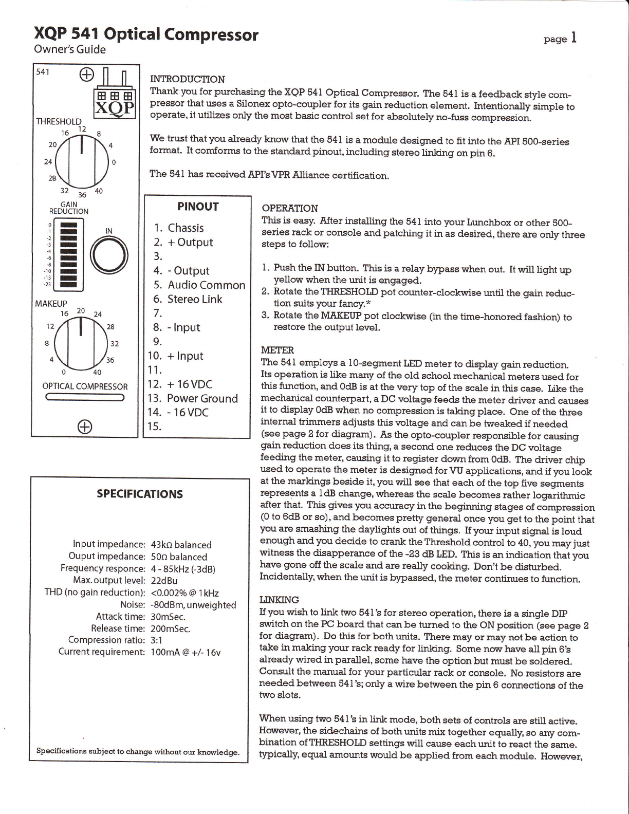
II{TRODUC1ION
Thankyoufor purchasing
theXQP
541Optical Compressor.
The541isafeedback stylecom-
pressorthat
uses
aSilonex
opto-couplerfor its grain
reductionelement. Intentionallysimpleto
operate,
it utilizesonly themostbasiccontrolsetfor absolutely
no-fuss
compression.
Wetrustthatyoualready
knorr thatthe541
isamoduledesigmed
tofit into theApIS00-series
format. It comforms to the stand,ard
pinout, including stereolinking onpin 6.
The541
hasreceived
API's1/PR
Atliancecertification.
PINOUT
1.
Chassis
2.+Output
3.
4.-Output
5.Audio
Common
6. Stereo
Link
7.
8.-
Input
9.
10.
+Input
11.
12.+16VDC
13.
PowerGround
14.
-
16VDC
15.
OPERATION
This is easy. After installing the s4I into your Lr:nchbox or other s00-
series rack or console and patching it in as desired, there are only three
steps to follow:
l. Push the IN button. This is a relay bypass when out. It will light up
yellow when the unit is engnged.
2. Rotate theTIIRESHOLD pot cor:nter-clocklyise until the gain reduc-
tion suits your fancy.*
3. Rotate the MAKEUP pot clockririse (in the time-honored fashion) to
restore the output level.
METER
The 541 employs a l0-segment tED metet to display gain reduction.
Its operation is like marry of the old school mechanical meters used for
this function, and OdBis at the rrery top of the scale in this case. Like the
mechanical counterpart, a DC rroltage feeds the meter driver and causes
it to display OdBwhen no compression is taking place. one of the three
internal trimmers adjusts this voltage and can be tweaked if needed
(see page 2 for diagram). As the opto-coupler responsible for causing
gain reduction does its thing, a second one reduces the DC voltage
feeding the meter, causing it to register down from OdB. r?re driver chip
used to operate the meter is designed for vU applications, and if you look
at the markings beside it, you will see that each of the top five segments
represents a ldB change, whereas the scale becomes rather logarithmic
after that. T?risgives you accurasy in the begirming stages of compression
(0 to 6dB or so),and becomes pretty general once you get to the point that
]rou are smashing the daylights out of things. If your input signal is loud
enough and you decide to crank the Threshold control to 40, you may just
witness the disapperance of the -m dB LED. This is an indication that you
have gone off the scaie and are really cooking. Don't be disturbed.
Incidentally, when the r.mitis bypassed, the meter continues to finction.
IINKING
If you wish to link two 541'sfor stereo operation, there is a single DIp
svuitchon the PC board that can be turned to the ON position (seepage 2
for diagram). Do this for both r.rnits.
There may or may not be action to
take in making your rack ready for linking. Some norr have all pin 6's
already wired in parallel, some have the option but mr,rst
be soldered.
consult the manual for your particr.rlar rack or console. No resistors are
needed between 541
's;only a wire between the pin 6 connections of the
two slots.
when using two 541
'sin link mode, both sets of controls are still active,
Hovyever, the sidechairs of both units mix together egually, so any com-
bination ofTIIRESHOLD settings will cause eachunit to react the same.
typically' egtral amounts would be applied from each module. However,
SPECIFICATIONS
lnput
impedance:
Ouput
impedance:
Frequency
responce:
Max.output
level:
THD
(no
gain
reduction):
Noise:
Attack
time:
Release
time:
Compression
ratio:
Currentrequirement:
43kobalanced
50n
balanced
4
-
sskHz
(-3dB)
22dBu
<4.002o/a
@l kHz
-80dBm,
unweighted
30mSec.
200mSec.
3:1
100mA
@+/-16v
Specifications subject to change without our knovrledge.