Basic Delay Mode
This is the default mode for the unit and can be accessed at any time by pressing 'QUIT'.
(press twice in Output Equalisation and Delay measurement modes).
Important. If temperature compensation is required, the ambient temperature must be
entered at the time of initial set-up. See Note. A. below.
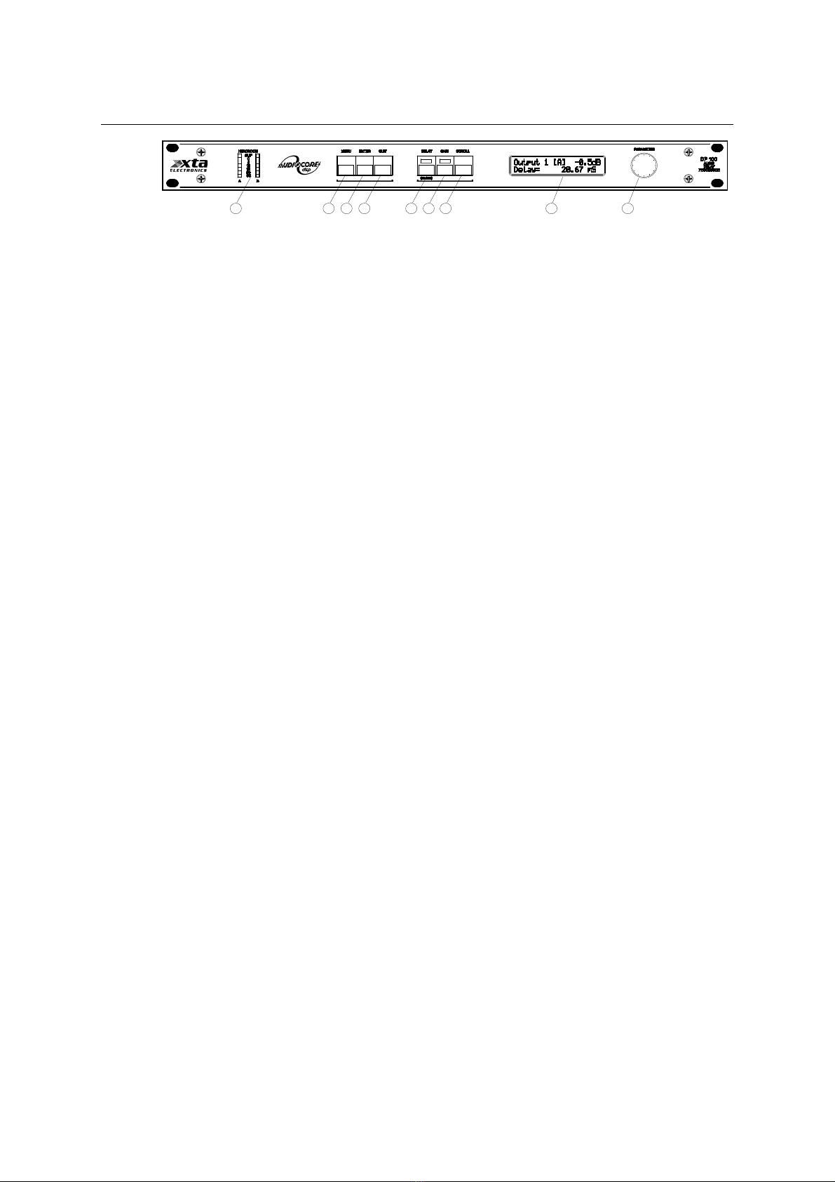
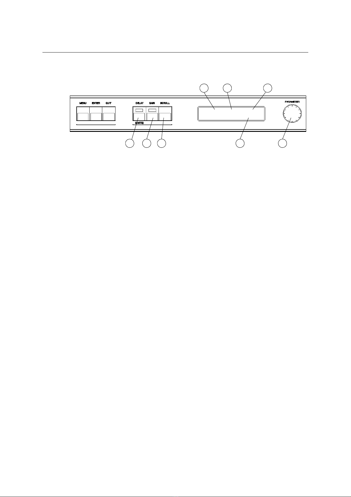
1.Output No. - shows the output currently selected for adjustment.
2.Input - shows which input the selected output is assigned to.
3.Output level - shows the current output level for the selected output.
4.Delay Time - shows the current delay time in milliseconds for the selected output. If
distance units are selected, display will read: Mt (metres), Ft (feet), PAL Frames or
NTSC Frames.
5.Parameter control - allows the selected parameter to be adjusted.
6.Delay Key - Allows the delay time to be adjusted, via the parameter control, for the
output currently shown in the LCD display. To avoid accidental adjustment, this function
will cancel after 15 seconds. A red LED shows the status of this key. Holding the Delay
key for 2 seconds changes the display units from Time in milliseconds to Distance in
either feet or metres (menu selectable) or visa versa.
7.Gain Key - Allows gain to be adjusted, via the parameter control, for the output
currently shown in the LCD display. 'Gain' is variable between 0dB and 40dB of
attenuation plus 'mute'. This function also cancels after 15 seconds.
8.Scroll Key - scrolls to the next output for previewing on the LCD display (and
adjustment if required). The display will also scroll through temperature function if
operating in the distance mode and base delay offset function if it has been enabled.
Note A: If Distance mode is selected (by holding down the Delay key for 2 seconds)
distance is controlled as delay time above and will be displayed in either feet or metres
depending on menu selection. In this mode Temperature compensation is possible: Press
scroll key to select temperature control, then press 'Delay' key and enter ambient
temperature at the time of set-up via the parameter control. Before the next performance
enter current ambient temperature - the time delay is automatically set to the correct value.
Note B: If Base Offset Delay is selected via menu, current offset value can be found using
scroll key and adjusted using parameter control. This function allows a set amount of delay
to be applied to all outputs assigned to particular input, allowing a multiple driver set-up to be
time aligned and then delayed as a system, maintaining time alignment. With this function
selected the delay time shown for each output is the total delay including any Base Offset
Delay.
DP100 Page 8
67 8 4 5
1 2 3
Output 1 [A] -7.5dB