Xtralis ADPRO VM22E User manual

ADPRO®
VM22E Audio
Switcher
Technical Manual
November 2017
Doc. 29541_03


ADPRO®VM22E Audio Switcher Technical Manual
29541_03 3
Disclaimer
The contents of this document are provided on an "as is" basis. No representation or warranty (either express or implied) is made as to the completeness,
accuracy or reliability of the contents of this document. The manufacturer reserves the right to change designs or specifications without obligation and
without further notice. Except as otherwise provided, all warranties, express or implied, including without limitation any implied warranties of merchantability
and fitness for a particular purpose are expressly excluded.
Intellectual Property and Copyright
This document includes registered and unregistered trademarks. All trademarks displayed are the trademarks of their respective owners. Your use of this
document does not constitute or create a license or any other right to use the name and/or trademark and/or label. This document is subject to copyright
owned by Xtralis. You agree not to copy, communicate to the public, adapt, distribute, transfer, sell, modify, or publish any contents of this document
without the express prior written consent of Xtralis.
General Warning
This product must only be installed, configured and used strictly in accordance with the General Terms and Conditions, User Manual and product
documents available from Xtralis. All proper health and safety precautions must be taken during the installation, commissioning, and maintenance of the
product. The system should not be connected to a power source until all the components have been installed. Proper safety precautions must be taken
during tests and maintenance of the products when these are still connected to the power source. Failure to do so or tampering with the electronics inside
the products can result in an electric shock causing injury or death and may cause equipment damage. Xtralis is not responsible and cannot be held
accountable for any liability that may arise due to improper use of the equipment and/or failure to take proper precautions. Only persons trained through an
Xtralis accredited training course can install, test and maintain the system.
Liability
You agree to install, configure, and use the products strictly in accordance with the User Manual and product documents available from Xtralis.
Xtralis is not liable to you or any other person for incidental, indirect, or consequential loss, expense or damages of any kind including without limitation,
loss of business, loss of profits, or loss of data arising out of your use of the products. Without limiting this general disclaimer the following specific warnings
and disclaimers also apply:
Fitness for Purpose
You agree that you have been provided with a reasonable opportunity to appraise the products and have made your own independent assessment of the
fitness or suitability of the products for your purpose. You acknowledge that you have not relied on any oral or written information, representation, or advice
given by or on behalf of Xtralis or its representatives.
Total Liability
To the fullest extent permitted by law that any limitation or exclusion cannot apply, the total liability of Xtralis in relation to the products is limited to:
(i) in the case of services, the cost of having the services supplied again; or
(ii) in the case of goods, the lowest cost of replacing the goods, acquiring equivalent goods or having the goods repaired.
Indemnification
You agree to fully indemnify and hold Xtralis harmless for any claim, cost, demand, or damage (including legal costs on a full indemnity basis) incurred or
which may be incurred arising from your use of the products.
Miscellaneous
If any provision outlined above is found to be invalid or unenforceable by a court of law, such invalidity or unenforceability will not affect the remainder which
will continue in full force and effect. All rights not expressly granted are reserved.
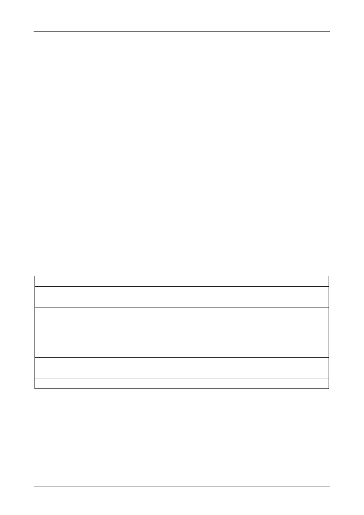
Document Conventions
The following typographic conventions are used in this document.
Convention
Description
Bold
Used to denote: emphasis
Used for names of menus, menu options, toolbar buttons
Italics
Used to denote: references to other parts of this document or other documents. Used for the result of an action
The following icons are used in this document.
Icon
Description
Note. This icon indicates information of special interest that will help the reader make full use of the product, optimise
performance, etc. Failure to read the note will not result in physical harm to the reader, or damage to equipment or data.
Caution! This icon indicates danger to equipment. The danger can be loss of data, physical damage to the equipment, or permanent
corruption of configuration details.
Warning! This icon indicates danger of physical harm to the reader. Not following instructions may lead to death or permanent injury.
Warning! This icon indicates danger of electric shock. This may lead to death or permanent injury.
Warning! This icon indicates that there is a danger of inhaling dangerous substances. This may lead to death or permanent injury.

Technical Manual ADPRO®VM22E Audio Switcher
4 29541_03
Trade Name Statement
Xtralis, the Xtralis logo, The Sooner You Know, VESDA-E, VESDA, ICAM, ECO, OSID, HeiTel, ADPRO, IntrusionTrace, LoiterTrace, ClientTrace,
SmokeTrace, XOa, XOh, iTrace, iCommand, iRespond, iCommission, iPIR, and FMST are trademarks and/or registered trademarks of Xtralis and/or its
subsidiaries in the United States and/or other countries. Other brand names mentioned herein are for identification purposes only and may be trademarks
of their respective holder(s). Your use of this document does not constitute or create a licence or any other right to use the name and/or trademark and/or
label.
Contact Us
UK and Europe +44 1442 242 330 D-A-CH +49 431 23284 1 The Americas +1 781 740 2223
Middle East +962 6 588 5622 Asia +86 21 5240 0077 Australia and New Zealand +61 3 9936 7000
www.xtralis.com
Environmental Information
The crossed-out wheeled bin means that within the European Union the product must be taken to separate collection at the product
end of life. This applies to the device but also to any accessories marked with this symbol. Do not dispose of these products as
unsorted municipal waste.
If you need more information on the collection, reuse, and recycling systems please contact your local waste administration. You can
also contact us for more information on the environmental specifications of our products.

ADPRO®VM22E Audio Switcher Technical Manual
29541_03 5
Contents
1Introduction............................................................................................................................................6
1.1 About the VM22E.........................................................................................................................6
1.2 Requirements ..............................................................................................................................6
1.3 Scope............................................................................................................................................6
1.4 Specifications..............................................................................................................................6
1.5 Front Panel...................................................................................................................................7
1.6 Back Panel...................................................................................................................................7
1.7 Ordering Information ..................................................................................................................7
2Hardware Installation ............................................................................................................................8
2.1 Summary......................................................................................................................................8
2.2 Required Material........................................................................................................................8
2.3 Connection Scheme....................................................................................................................9
2.4 Connection to the MIO Card.....................................................................................................10
2.5 Ground (GND) Connection.......................................................................................................10
2.6 Cascading Multiple VM22E Units.............................................................................................10
2.7 Addressing.................................................................................................................................10
2.8 Output Channel Numbering .....................................................................................................11
2.9 Forcing Output to Channel 1....................................................................................................11
3Setup in the XO Client Software ........................................................................................................12
3.1 Summary....................................................................................................................................12
3.2 Checking and Updating the MIO Card Firmware ...................................................................12
3.3 Activating the VM22E Audio Switcher ....................................................................................13
3.4 Assigning Audio Channels to Cameras..................................................................................13
3.5 Volume Control..........................................................................................................................14

Technical Manual ADPRO®VM22E Audio Switcher
6 29541_03
1 Introduction
1.1 About the VM22E
The ADPRO®VM22E audio switcher allows you to switch the audio output from an ADPRO device to one of
4 selectable audio outputs on the VM22E. You can connect up to 8 VM22E units in cascade, creating up to
32 different output channels.
The VM22E is compatible with the following ADPRO devices:
FastTrace 2 Series: FastTrace 2, FastTrace 2X, FastTrace 2E
iFT Series: iFT, iFT-E.
1.2 Requirements
ADPRO device firmware version XOa 3.00.0005 or above
Main I/O (MIO) card firmware version v01.00.0004 or above.
1.3 Scope
This manual covers:
The hardware installation of the VM22E, the connection to the ADPRO device, and the cascade
connection.
The software configuration in the XO client.
This manual does not cover the detailed setup and installation of amplifiers and speakers.
1.4 Specifications
Power supply
10–14 VDC via external power adapter (first unit only)
Current
60 mA per unit (@ 12 VDC)
Cascade
Up to 8 units, via flat cable
Audio input
3.5 mm jack (mini jack)
Max. 4 Vpp, input impedance 100 kΩ
Audio output to amplifier
4 x RCA connector (cinch)
Max. 4 Vpp, output impedance 120 Ω
Dimensions
105 x 46 x 100 mm (W x H x D)
Housing
Black anodised aluminium
Operating temperature
0–40 °C
Humidity
20–93 % (non-condensing)

ADPRO®VM22E Audio Switcher Technical Manual
29541_03 7
1.5 Front Panel
#
Description
1
Unit address selector (rotary switch)
2
LED indicator, power
3
LED indicators, input volume from ADPRO
device
4
LED indicators, output channel 1–4
1.6 Back Panel
#
Description
5
12 VDC power plug
6
Flat cable connector for cascading units
7
Screw terminal connector for wiring to
ADPRO device’s MIO card
8
Audio input from ADPRO device, 3.5 mm
jack
9
Audio outputs 1–4 to amplifier, RCA (cinch)
1.7 Ordering Information
Use the following reference numbers to place your order with Xtralis:
Item
Reference number
VM22E unit
including 4-socket flat cable and mini-jack audio cable
49840500
8-socket flat cable
21767200

Technical Manual ADPRO®VM22E Audio Switcher
8 29541_03
2 Hardware Installation
2.1 Summary
To physically set up a system with one or more VM22E units, perform the following steps:
1. Connect the first VM22E unit to the ADPRO device via the MIO card.
2. Connect the first VM22E unit to the ADPRO device’s audio line out.
3. Connect the VM22E unit(s) to the necessary amplifiers and speakers.
4. In case of multiple units in cascade: interconnect the units.
5. Set the VM22E unit(s) address(es).
6. Power the first VM22E unit.
2.2 Required Material
You need the following material:
Item
Included
VM22E unit (one unit per 4 required audio output channels)
Yes
12 VDC power supply
No
Cable for connecting the VM22E to the MIO card
No
Audio cable (2 x 3.5 mm jack) for connecting the VM22E to the ADPRO
device’s audio output
Yes
Audio amplifiers and speakers
No
RCA cables (cinch) for connecting the VM22E to the amplifier
No
Flat cable for cascading units
Yes, for cascading 4 units*
(*) If you need to cascade more than 4 VM22E units, you can order an 8-socket flat cable separately. For details, see
Ordering Information on page 7.
Power supply specifications:
12 VDC; min. 500 mA for cascading 8 VM22E units (60 mA per unit @ 12 VDC)
Plug: 5.5 x2.5 mm male DC plug (0.22 x0.098 in).
Cabling to MIO card: standard alarm cable (min. 5 cores) is sufficient if you keep the distance between the
ADPRO device and the VM22E unit as short as possible.

ADPRO®VM22E Audio Switcher Technical Manual
29541_03 9
2.3 Connection Scheme
For the hardware installation of the VM22E, see the connection scheme below. You can find detailed
information further below.
#
Description
A
12 VDC power supply (1st unit only)
B
Back panel first VM22E module
C
ADPRO device rear panel
D
ADPRO device line out (green 3.5 mm jack) to VM22E audio input (3.5 mm jack).
E
ADPRO device MIO card connection to VM22E. For details, see Connection to the MIO Card on
page 10.
F
(Optional) ADPRO device casing ground screw connected to ground terminal on VM22E. For
details, see Ground (GND) Connection on page 10.
G
Amplifier back panel
H
Single speaker connection example
I
VM22E audio output channel 1 to amplifier’s audio input, RCA cable
J
Amplifier back panel
K
Distributed (parallel) speaker connection example, for broadcasting
L
VM22E audio output channel 2 to amplifier’s audio input, RCA cable
M
Connect more amplifiers as required
N
Back panel second VM22E module
O
Cascade connection, up to 8 VM22E units
P
Flat cable connection between VM22E units. For details, see Cascading Multiple VM22E Units on
page 10.

Technical Manual ADPRO®VM22E Audio Switcher
10 29541_03
Note
Keep the distance between the ADPRO device and the VM22E units as short as possible.
2.4 Connection to the MIO Card
The table below lists the correct connections between the VM22E module and the ADPRO device’s MIO
card:
VM22E terminal
MIO card Next Generation
MIO card
No.
Name
No.
Name
ST
30
STROBE
21
TA / STROBE
0V
33
GND
23
0V
CL
36
CLOCK
24
RA / CLOCK
DA
38
DATA
25
RB / DATA
33
GND
23
0V
2.5 Ground (GND) Connection
A correct ground interconnection between devices can eliminate humming. For the ground (GND)
interconnection between the VM22E and the ADPRO device, you have the following options:
From the terminal on the VM22E to the GND/0V terminal on the MIO card (E).
From the terminal on the VM22E to the ground screw on the chassis of the ADPRO device (F).
2.6 Cascading Multiple VM22E Units
You can connect up to 8 VM22E units in cascade to an ADPRO device, providing a total of 32 audio output
channels.
To connect multiple VM22E units in cascade, proceed as follows:
1. Connect the power supply to the first VM22E unit. It is not necessary to power the other units
separately; they will receive power via the interconnecting flat cable.
2. Set up the connections to the ADPRO device on the first VM22E unit (MIO card and audio line out).
You do not need to connect the other units to the ADPRO device; they will receive the audio and
control signals via the interconnecting flat cable.
3. Use the flat cable to interconnect the VM22E units (P). Interconnect maximum 8 units.
Note
The standard supplied flat cable has 4 connectors; you can order a cable with 8 connectors if
necessary. If you use less than 4 or 8 units, Xtralis recommends to use the connectors at the
ends of the cable, and leave the connectors in the middle unused.
2.7 Addressing
Whether you use only one VM22E unit or several units in cascade, you must always set the unit’s address,
to make sure that the system will send the output from the ADPRO device to the correct speaker. Proceed as
follows:
Set the rotary switch on the VM22E front panel to the desired address in the 0–7 range.
Addresses 8 and 9 are not suitable for switching audio; they are used for forcing the audio output to
channel 1. For more information, see Forcing Output to Channel 1 on page 11.

ADPRO®VM22E Audio Switcher Technical Manual
29541_03 11
2.8 Output Channel Numbering
The table below shows how the audio output numbers (1–32) in the XO client software correspond with the
VM22E addresses (rotary switch setting 0–7) and the VM22E audio channel numbers (1–4).
VM22E
address
Audio channel on VM22E unit
1
2
3
4
0
1
2
3
4
1
5
6
7
8
2
9
10
11
12
3
13
14
15
16
4
17
18
19
20
5
21
22
23
24
6
25
26
27
28
7
29
30
31
32
For example: audio output 11 in the XO client corresponds with audio channel 3 on the VM22E with
address 2.
2.9 Forcing Output to Channel 1
If you want to force the audio input from the ADPRO device to output channel 1 on the VM22E unit, set the
unit’s address to 8 or 9. The system then transmits the audio input from the ADPRO device to the speaker
on channel 1, regardless of the settings in the XO client.

Technical Manual ADPRO®VM22E Audio Switcher
12 29541_03
3 Setup in the XO Client Software
3.1 Summary
To set up audio output via the VM22E switchers, perform the following steps in the XO client software:
1. In the MIO card configuration, check if the MIO card has firmware version v01.00.0004 or above.
2. In the MIO card configuration, activate the VM22E switcher type. This will make sure that the MIO card
sends the correct signals to the VM22E unit(s).
3. Assign the VM22E audio output channels to cameras. When you use the talkback button with a
camera in the Live Video window, the system will send the sound to that camera’s assigned audio
output channel.
Each step is explained in detail in the sections below.
3.2 Checking and Updating the MIO Card Firmware
To check and update the MIO card firmware, proceed as follows:
1. Open the XO client software, and choose System > Connections > I/O.
2. Check if the firmware version of the MIO card is minimum v01.00.0004.
- If yes, you can skip all following steps, and proceed with Activating the VM22E Audio Switcher on
page 13.
- If no, continue with the next step.
3. Download and unzip the MIO card firmware from the Xtralis Security Support site
www.xtralissecurity.com. Search for keyword USBIO to find the file; filter on Information Type =
Firmware.
4. In the XO client, click Update.
5. Click the button and browse to the .img file with the latest software version.
6. Click Open. The Version box displays the software version that you will upload.
7. Click Update. The device beeps while the system installs the new software (about 5 seconds).
8. When finished, click Cancel to close the update box.
9. Continue with activating the VM22E audio switcher.

ADPRO®VM22E Audio Switcher Technical Manual
29541_03 13
3.3 Activating the VM22E Audio Switcher
To activate the VM22E audio switcher, proceed as follows:
1. Open the XO client software, and choose System > Connections > I/O.
2. Click Configuration.
3. Under Audio switcher type, click VM22E.
4. Click OK.
5. Click Save.
3.4 Assigning Audio Channels to Cameras
To assign audio output channels to the cameras, proceed as follows:
1. Choose System > Connections > Audio.
2. Click the Audio output tab.
For software versions below XOa 3.01, the following screen appears:

Technical Manual ADPRO®VM22E Audio Switcher
14 29541_03
For software versions XOa 3.01 and above, the following screen appears:
By default, the system associates each camera to the audio output with the matching number
(camera 1 to output 1, camera 2 to output 2…). For the numbering of the audio outputs, see Output
Channel Numbering on page 11.
3. For each camera, proceed as follows:
- For software versions below XOa 3.01: type the number of the desired audio output (1–32) in the
Selected audio output column.
- For software version XOa 3.01 and above: click in the Selected VM22 output column and type
the number of the desired audio output (1–32).
4. Click Save.
3.5 Volume Control
The VM22E unit has an input volume indicator on the front panel. If the input volume from the ADPRO
device is too high, the yellow and red LEDs light up:
Yellow: 0 dBm (2.2 Vpp)
Red: +3 dBm.
Note
Audio signal clipping occurs at about +6 dBm (4 Vpp).
To adjust the input volume, use the volume slider in the Live Video window in the XO client:


www.xtralis.com
UK and Europe +44 1442 242 330 D-A-CH +49 431 23284 1 The Americas +1 781 740 2223
Middle East +962 6 588 5622 Asia +86 21 5240 0077 Australia and New Zealand +61 3 9936 7000
A Disclaimer about this document, statements about Intellectual Property, Copyrights, and Liability, as well
as a General Warning are available in an earlier section of this document.
Doc. 29541_03 P/N 19532160
Table of contents
Popular Switch manuals by other brands

Coherent Solutions
Coherent Solutions SwitchBlade user manual

SMC Networks
SMC Networks SMC8612XL3 F 1.0.1.3 Technical specifications

Key Digital
Key Digital KD-UFS42 quick start guide

Endress+Hauser
Endress+Hauser Liquiphant T FTL20 manual

SamplexPower
SamplexPower STS-30 owner's manual

Texas Instruments
Texas Instruments HPL-D SLLU064A user guide

D-Link
D-Link DES-1200M user guide

Draytek
Draytek VigorSwitch P2500 quick start guide

Tycon Power Systems
Tycon Power Systems TP-SW8GAT/24-SFP user manual

GMTechtronics
GMTechtronics GMT-RC01 user manual

steute
steute KF Mounting and wiring instructions

ZyXEL Communications
ZyXEL Communications GS2200-24 Series Specifications