XtremepowerUS 75217 User manual

SWIMMING POOL HE PUMP
ITEM# 75217
OWNER'S MANUAL AND SAFETY INSTRUCTIONS

1
The Swimming Pool Heat Pump Unit is intended to heat the swimming pool water and regulate the
temperature. Use in any other application will void the warranty.
The inlet & outlet connections cannot support any load from another piping system.
Make certainthe air outlet is not directed towards any person, animal, or vegetation.
The unit must always be powered off before opening the access panel. Always turn of circuit supplying power
to the unit prior to removing the access panel or performing any electrical work on the unit.
All electrical connections must be performed by a qualifiedelectrician and according to national and local
electrical codes. We have provided important safety messages in this manual and on your heat pump. Always
read and obey all safety messages.
You will need to set the water temperature you desire.
Always install the machine outdoors, while adhering to the minimal clearances needed for proper operation
and heating. DO NOT place the unit next to shrubs, fences, etc. which can block the air inlet. These locations
deny the unit a continuous source of fresh air which reduces its efficiency and may prevent adequate heat
delivery.
Heat Pumps must be installed in accordance with all applicable National and Local codes. In the absence of
local codes, refer to the latest edition ofthe Canadian Electrical Code (CEC).
The unit will automatically start up whenthere is proper flow and available power.
If the unit is stopped for an extended period of time or winterized, itmustbe drained of all water. You will need
to disconnect the IN and OUT water connections. Then the unit must then be tilted or blown out with air until all
water is out.
Do not insert any objects into the air outlet. Do not attempt to disassemble the fan at any time.
If at any time there is any abnormal noise, odor, smoke, electricity leakage, please switch off power
immediately and contact your local dealer. All repairs must be performed byaqualified technician.
Do not store combustible or flammable material near unit.

2
Note: There may be variations in values due to climatic conditions.

3
SWIMMING
POOL WATER
TREATMENT
SYSTEM
STOP VALVE
STOP VALVE
Diagram for Water Piping Connections
Note: The diagram is for demonstration purposes only, and layout of the pipes is
for reference only.
Electric Wiring Diagram
Note: The swimming pool heat pump must be grounded.
WATER TO SWIMMING POOL
THREE WAY
VALVE
Pump
THREE WAY
VALVE
POOL WATER

4
Protecting devices and cable specification
1. Always install the machine outdoors, while respecting the minimal clearances needed for proper
operation and heating. DO NOT place the unit next to shrubs, fences, etc. which can block the air
inlet. These locations impede the unit a continuous source of fresh air which reduces its efficiency
and may prevent adequate heat delivery.
2. Mount the unit on a sturdy and level base, preferably a concrete slab. The base should be
completely isolated from the building foundation wall to prevent the possibility of sound or vibration
transmission into the building
.
3. The pool heat pump is designed for outdoor installation only and should not be installed in a fully
enclosed area, such as a shed, garage, etc. Recirculation of cold discharged air back into the
evaporator coil will greatly reduce unit heating capacity and efficiency. Air is pulled through the
evaporator coil and discharged through the side grille. A minimum clearance of 98 inches should be
allowed on the air outlet side for unrestricted air discharge. The unit must not be installed under a
porch. Any other side of the unit should be located at least 28 inches from a wall or from any other
obstruction for unrestricted air intake and service access.
Breaker Rated Current : 20 A
Breaker Rated Residual Action Current : 30 mA
Fuse : 25 A
Power Cord (AWG) : 3X12
Signal Cable (AWG) : 3X20
Note: The above data is for an electrical cord of less than 10 m. If electrical cord is > 10 m, wire
diameter must be increased. The signal cable can be at maximum 50 m.
Pump protecting device cable specification is subject to user’s option
Installation Instruction and Requirements:
All electrical connections must be performed by a qualified electrician and according to national and
local electrical codes. We have provided important safety messages in this manual and on your heat
pump. Always read and obey all safety warnings. Heat Pumps must be installed in accordance with
all applicable National and Local codes. In the absence of local codes, refer to the latest edition of the
Canadian Electrical Code (CEC).
INSTALLATION
Scan the QR Code to watch the installation video.

5
4. The piping sequence is asfollows: pool > pool pump >filter > heat pump >check valve>
chemical feeder pool. Automated chlorine distributionsystems, ifused, must be placed
downstream of the heat pump tominimize harm to the pool equipment. Use rigid PVC piping if
possible (SCH40 or SCH80). All joints should be glued with PVC glue. When the piping
installation is complete, operate the pool pump and check the system for leaks. Then, check
the filter pressure gauge to verify that there isn’t any indication of excessive pump head
pressure.
You can also make the connections using high-pressure flexible hose, but make sure the hose
can withstand high pressure.
I) It is also normal to see water dripping from the drain at the base pan of the unit. While your
pool heat pump is in the heating mode, alarge volume of warm and humid air passes over
the evaporator and causes condensation. To determine ifthere is a leak, you must stop the
heat pump and leave the pool pump running for at minimum 5hours. If water is still coming
out of your heat pump after this period, then call your dealer for service
.
Wiring
1. The wiring of your pool heat pump should be performed by aqualified electrician in
accordance with local requirements. A properly-sized breaker and copper wire must be used.
Check the heat pump data required maximum breaker size. Because all metals have different
electrical potentials, all metal and electrical components of the pool system mustbe bonded
together. This includes the metal framework ofthe pool, the light, the pump, the filter (if made
out of metal), the heat pump, any automatic chlorine generator, and any other metal or
electrical equipment. On some older pools, this substructure bond wire may not exist. In
these cases, a 6 to 8 foot solid copper rod must be driven into the ground near the
equipment. All electric and metal components must then be bonded to each other, and then to
the copper rod.
2. The wiring of your pool heat pump must be performed by aqualified electrician in
accordance with national and local requirements
.
3. Set leakage protector according to the local code for wiring (leakage operating current ≤
30mA)
.
4. The layout ofpower cable and signal cable should be orderly and not affecting each other.
5.
Once all wiring and connections have been completed and checked power to the unit
can be turned back on.

6
Set the operation parameter:
◎When the unit powered up but not running, long Press “ ” button 3S to enter operation parameter setting
interface.
◎Press " " to check parameter(parameter from P01-P14, see Operation Parameter Table).
◎Under parameter, press " " to start setting(the parameter displayed blinks), press " " or " " to set
data for parameter from P01-P14, press " " again to exit the current parameter settings.
◎In operation parameter setting interface, press " " button exit to man interface, No operation is maintained in
the parameter interface.
◎If the heat pump is running, press " " 3S to check parameter, but can’t change parameters.
NO Meaning Range Change Factory setting
P01 Cooling setting water temperature 50~113°F YES 79°F
P02 Heating setting water temperature 50~113°F YES 79°F
P03 Turnround of defrosting Under heat mode 30~90 min YES 45min
P04 Defrosting start temperature 32~86°F YES 19°F
P05 Defrost exit temperature 30~86°F YES 56°F
P06 Time of exit defrost Under heat mode 1~12 min YES 5 min
P07 Mode (cool/cool & heat/E-heat/heat) 0/1/2/3 YES 1
P08 EEV manual/automatic 0/1 NO 1
P09 Heating Target Superheat 5~59°F NO 34°F
P10 Cooling Target Superheat 5~59°F NO 25°F

7
P11 Auto mode setting water temperature 50~113°F YES 79°F
P12 Compressor protection Exhaust temperature 185~230°F NO 203°F
P13 Low ambient temperature protection -4~50°F YES 5°F
P14 EEV manual step number 18~94 NO 70
Check system current status
Press “ ”button 3Stoenter check system current status interface.
NO Meaning Range Remarks
A01 Water temperature -4~210°F Measured value
A02 Compressor Exhaust temperature -4~257°F Measured value
A03 Heating coil temperature -4~210°F Measured value
A04 Return gas temperature -4~210°F Measured value
A05 Ambient temperature -4~210°F Measured value
A06 Cooling coil temperature -4~210°F Measured value
A07 Manual Control for EE valve 18~94 Measured value

8
Real-time clock setting
Press“" + “ ”button 3S to set clock,
“" symbol will flash during this setting,
Press " " button, it will enter hour setting,
press “ ” or “ ” buttons to change the value.
Press " " button once more, it will enter minute setting.
Also press “ ” or “ ” buttons to change the value.
After setting, press “ ” button to back to default screen.
Timer setting
Once the time has been set correctly, this function allows a machine start time and a machine stop time to be
programmedduring the day
Press “ ” botton 3S the time displayed and “1-NO” to blink. Change the hour using the “ ” or “ ” keys.
Press “ ” botton again to change the minutes using the“” or “ ”keys.
Press “ ” botton the time displayed and “1-OFF” to blink. Change the hour using the“” or “ ”keys.
Press “ ” botton again to change the minutes using the “” or “ ” keys.
Press “ ” botton again the display returns to normal.
The time setting is from 0 to 24 hours to recycle.
When the setting timer for on and off is the same,the setting timer is not available.
When the setting timer(displayed blinks), Press “ ” to deactivate TIMER.
Coercive Defrosting:
1. press “ ” bottom5seconds when the unit is heating mode, the unit go to
defrost state.
2. When fulfilled defrost stop conditions, defrost is stopped.
Key lock:
Long press “ ”and “ ” button 3 seconds, To set keylock.
Long press “ ”and “ ” button 3 seconds again to release keylock.

9
TESTING
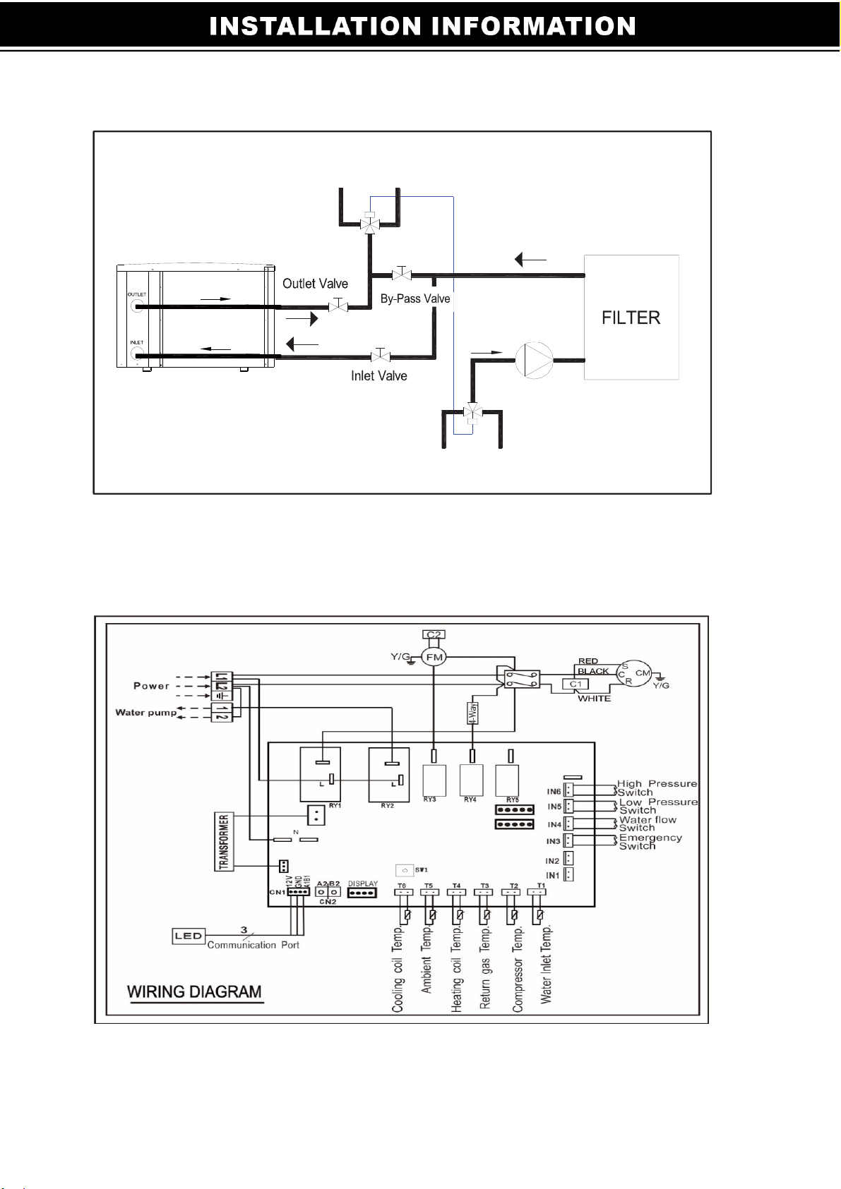
Inspection before use
Trial
oCheck installation ofthe whole machine and the pipe connections according to the pipe
connection diagram
oCheck the electric wiring according to the electric wiring diagram; and make sure the Heat Pump is
bonded
oMake sure that the main machine power switch is off
oCheck the temperature setting.
oCheck the air inlet and outlet.
•The user must “Start the Pump before the Machine, And Turn off the Machine before the
Pump”, or the machine will be damaged
•The user should start the pump, check for any water leakage of water; set temperature
in the thermostat, and then switch on power supply.
•In orderto protect the swimming pool heat pump, the machine is equipped with a time delay
starting function, when starting the machine, the blower will run for 3 minutes before the
compressor starts.
•If at anytime there is an abnormal noise, smell, smoke, electricity leakage, please switch off power
immediately and contact your local dealer.
Attention
oSet temperature control to achieve a comfortable water temperature and to avoid overheating or
over cooling.
oAlways install the machine outdoors, while noting the minimal clearances needed for proper operation
and heating. DO NOT place the unit next to shrubs, fences, etc. which can block the air inlet. These
locations deny the unit acontinuous source of fresh air which reduces its efficiency and may prevent
adequate heat delivery.
oNever put hands or any objects into outlet of the swimming pool heat pump, and don’t remove the screen
over the fan at any time.
oIf at any time there is an abnormal noise, odor, smoke, electricity leakage, please switch off power
immediately and contact your local dealer.
oDo not use orstock combustible gas or liquids such as paint thinners, paint, fuel near or aroundthe heat
pump.
oAs with all pool heat pumps, you are advised to use a pool cover at night and when the pool is not in
use.
oThe heat pump should be installed within 10m of the pool to minimize heat loss in the underground
pipes.
Safety
Please keep the main power supply switch out of reach from children.
oIf there is a power outage while the machine is in operation, the heat pump will start up automatically
when power is restored.
oPlease switch off the main power supply during lightening storms to prevent any damage to the unit.
oIf the machine is stopped for a long time, please cut off the power supply and drain water of the machine
by opening the tap of inlet pipe. If the unit is stopped for a long period of time or for winterizing, the unit
must be drained of all its water. You will need to disconnect the IN and OUT water connections. Then the
unit must be tilted or blown out with air until all water is out.

10
i. Disconnect power supply of the heat pump before any examination and repair. The unit must
always be powered off before opening the access panel. Always cut off the unit’s main power
whenever the access panel is open or removed.
ii. In winter seasons, please drain water clear of the machine, disconnect power Supply to
prevent any machine damage, and cover the machine body with plastic cover to avoid dust.
If the unit is stopped for a long period of time or for winterizing, the unit must be drained of all
its water. You will need to disconnect the IN and OUT water connections. Then the unit must
be tilted or blown out with air until all water isout.
iii. Please clean this machine with household detergents or clean water, NEVER gasoline,
thinners or any similar fuel. The areaaround the unit should be dry, clean and well
ventilated. Clean the side heating exchanger regularly to maintain good heat exchange and
conserve energy. Dirt can accumulate on the evaporator. You can easily remove it by using
a non-pressured water spray without damaging the small aluminum fins. The cleaning of the
plastic cabinet can be done with the help of a brush and soap.
iv. Check bolts, cables and connections regularly.
TROUBLESHOOTING

11
b) This table explains the error codes caused by a defective regulating component.
Displ
ay
Problem Cause Solution
E20 “WATER IN” sensor out of
order
Sensor open or short-circuited Check or replace the sensor
E10 “Compressor exhust”
sensor out of order
Sensor open or short-circuited Check or replace the sensor
E09 “HEATING COIL PIPE”
sensor out of order
Sensor open or short-circuited Check or replace the sensor
E12 “Return Gas”sensor out of
order
Sensor open or short-circuited Check or replace the sensor
E04 “AIR” sensor out of order Sensor open or short-circuited Check or replace the sensor
E25 “COOLING COIL PIPE”
sensor out of order
Sensor open or short-circuited Check or replace the sensor
E14 First anti-frost protection
active
Low temperatures for water
and air
No action required
Second anti-frost
protection active
Low temperatures for water
and air
No action required
PP9 Low ambient temperature
protection
Ambient temperature is too
low or protection temperature
setting set too high
Check andrepair.
E05 High pressure protection Insufficient water flow Check the water flow
Pressure switch out of order Replace the pressure switch Have
Too much refrigerant gas
present
the heat pump checked by a
refrigeration technician
E06 Low pressure protection Not enough refrigerant gas Have the heat pump checked by a
refrigeration technician
Leak in the cooling conduits Have the heat pump checked by a
refrigeration technician
E03 Insufficient water flow Insufficient water flow Check the water flow
Water flow switch out of order Replace theWater flow switch
PEE Phase Protection Faulty phase wiring Put phases in order
E07 compresso exr haust
temperature is too high
Water temperature and
environmental temperature is
too high
Set to the safety of water
temperature.
Refrigerant leakage Check and repair.
Insufficient water flow Check the water flow
E08 Communication failure No communication between
the digital display and the
system controller
Check the connection between the
screen and the controller.
Replace screen and/or controller.
PE2 Emergency switch
disconnect
Emergency switch disconnect Check and repair.
TROUBLESHOOTING

12

PLEASE READ THE FOLLOWING CAREFULLY
13
Table of contents
Popular Heat Pump manuals by other brands

Hisense
Hisense AHM-044HCDSAA Service handbook

Danfoss
Danfoss Optyma Slim Pack OP-LSQM Series instructions

Nordyne
Nordyne Q3RD User's manual & installation instructions

Viessmann
Viessmann Vitocal 350-G Installation and service instructions for contractors

Ferroli
Ferroli OMNIA H Series Installation, maintenance and user manual

AAON
AAON RN Series Installation operation & maintenance

Dimplex
Dimplex SIW 6TES Installation and operating instruction

Lennox
Lennox Allied Air Enterprises BHP16L installation instructions

Steinbach
Steinbach heatUP 650 Original instructions

Daikin
Daikin VRV-WII RWEYQ-MY1 Series Technical data

Daikin
Daikin ETVZ16S23DA6V User reference guide

Mitsubishi Electric
Mitsubishi Electric EHWT17D-MHEDW Data book