Yadea C1S User manual

C1S ELECTRIC MOTOR
SERVICE MANUAL
YD1800D-02
General
Information
Motor
Frame &
Chassis
Electrical
System


General Information
1
A Few Words About Safety ……………………………………… 2
How To Use This Manual ………………………………………… 4
Vehicle Information ……………………………………………… 5
SPECIFICATIONS ………………………………………………… 6
CABLE & HARNESS ROUTING ………………………………… 9
MAINTENANCE SCHEDULE …………………………………… 14

General Information
2
A Few Words About Safety
Service Information:
The service and repair information contained in this manual is intended for use by qualified, professional technicians.
Attempting service or repairs without the proper training, tools, and equipment could cause injury to you or others. It could also
damage the vehicle or create an unsafe condition.
This manual describes the proper methods and procedures for performing service, maintenance and repairs. Some procedures
require the use of specially designed tools and dedicated equipment. Any person who intends to use a replacement part, service
procedure or a tool that is not recommended by Yadea, must determine the risks to their personal safety and the safe operation
of the vehicle.
If you need to replace a part, use Yadea genuine parts with the correct part code or an equivalent part. We strongly recommend
that you do not use replacement parts of inferior quality.
For the Owner's Safety:
Proper service and maintenance are essential to the customer’s safety and the reliability of the vehicle. Any error or oversight
while servicing a vehicle can result in faulty operation, damage to the vehicle, or injury to others.
• Improper service or repairs can create an unsafe condition that can cause your customer to be seriously
hurt or killed.
• Follow the procedures and precautions in this manual and other service materials carefully.
For Your Safety:
Because this manual is intended for the professional service technician, we do not provide warnings about many basic shop
safety practices (e.g., Hot parts–wear gloves). If you have not received shop safety training or do not feel confident about your
knowledge of safe servicing practice, we recommended that you do not attempt to perform the procedures described in this
manual.
Some of the most important general service safety precautions are given below. However, we cannot warn you of every
conceivable hazard that can arise in performing service and repair procedures. Only you can decide whether or not you should
perform a given task.
• Failure to properly follow instructions and precautions can cause you to be seriously hurt or killed.
• Follow the procedures and precautions in this manual and other service materials carefully.

General Information
3
For Handling This Vehicle:
• Be sure to turn the main switch OFF and remove the battery before checking or servicing of parts removal/
installation.
• To prevent electric shock, always wear safety protective gears and use insulation tools when checking or
servicing of parts removal/installation.
• Do not work with wearing any metal items.
• Do not work in places where the floor is wet or raindrops fall on.
• When the electrolyte from the battery gets in eyes or on skin, there is a danger of blindness or damage,
so work with precaution. If electrolyte gets in your eyes or on your skin, immediately wash the area with
plenty of water and get medical examination by a specialist.
Avoid using a high-pressure water machine as washing vehicle with high water pressure may cause malfunction of moving parts
or electric parts.
Important Safety Precautions:
Follow the instructions below when checking and servicing the high voltage system.
In this manual, the power supply circuit above DC 48 V series is referred to as high voltage system. Do not touch the wires and
related parts carelessly.
When performing the vehicle maintenance, be sure to wear safety protective gears and use insulation tools. Always check the
safety protective gears and insulation tools for damage before using.
Ensure the safety of others by indicating that the high voltage works is being done on the vehicle when performing work relating
to the high voltage.
Make sure you have a clear understanding of all basic shop safety practices and that you are wearing appropriate clothing and
using safety equipment. When performing any service task, be especially careful of the following:
Read all of the instructions before you begin, and make sure you have the tools, the replacement or repair parts, and the skills
required to perform the tasks safely and completely.
Protect your eyes by using proper safety glasses, goggles or face shields any time you hammer, drill, grind, pry or work around
pressurized air or liquids, and springs or other stored-energy components.
Handling hot or sharp parts can cause severe burns or cuts. So, use other protective wear when necessary, for example gloves
or safety shoes.
If you need to support the vehicle for maintenance, please use jack or special base. Whenever you lift the vehicle, make sure
that the vehicle is always firmly supported.

General Information
4
How To Use This Manual
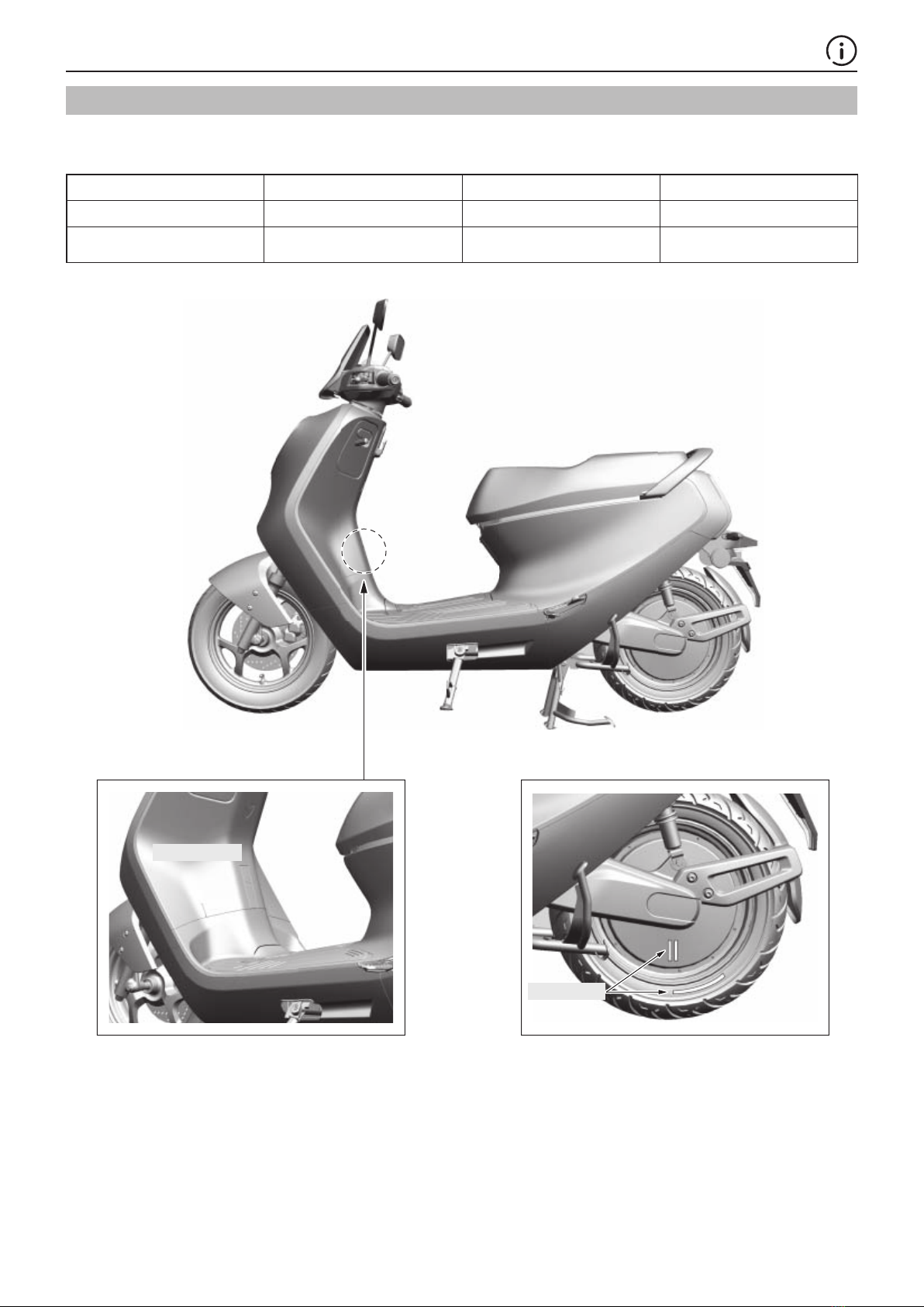
This manual is Specific Service Manual for C1S. In order to better meet the needs of customers and service providers for the
maintenance and repair of two-wheel electric vehicles, as well as the needs of service providers, after-sales maintenance
technicians and the marketing and training departments, we have specially prepared a version maintenance manual. This
manual specifically introduces the repair and maintenance information of this type of vehicle. For the basic operation instructions
of the vehicle, please refer to the product manual of the vehicle.
This manual explains how to diagnose, adjust, operate, and replace (repair) the entire vehicle and its parts; it also gives detailed
instructions on how to disassemble and assemble the main parts. Before consulting this book, readers are requested to read the
following information:
Your safety, and the safety of others, is very important, so we provide safety and other information related to vehicle
maintenance in this manual. Of course, it is not practical or possible to warn you about all the hazards associated with servicing
this vehicle. You must use your own good judgement.
You will find important safety information in a variety of forms including:
• Safety Labels – on the vehicle
• Safety information is preceded by one of the following three warnings: danger, warning or attention. These signal words mean:
You WILL be KILLED or SERIOUSLY HURT if you don’t follow instructions.
You CAN be KILLED or SERIOUSLY HURT if you don’t follow instructions.
You CAN be HURT if you don’t follow instructions.
• Instructions – how to service this vehicle correctly and safely.
As you read this manual, you will find information that is preceded by “NOTICE”. The purpose of this message is to help prevent
damage to your vehicle, other property, or the environment.
Before servicing each part, please find the corresponding chapter of the faulty part, and do not blindly inquire.
The data in this manual is the data recommended by the editor, and some data (such as tightening torque, etc.) is a range, so
please select the appropriate data according to the specific situation.
ALL INFORMATION, ILLUSTRATIONS, DIRECTIONS AND SPECIFICATIONS INCLUDED IN THIS PUBLICATION ARE
BASED ON THE LATEST PRODUCT INFORMATION AVAILABLE AT THE TIME OF APPROVAL FOR PRINTING. YADEA
TECHNOLOGY GROUP CO.,LTD. RESERVES THE RIGHT TO MAKE CHANGES AT ANY TIME WITHOUT NOTICE AND
WITHOUT INCURRING ANY OBLIGATION WHATSOEVER. NO PART OF THIS PUBLICATION MAY BE REPRODUCED
WITHOUT WRITTEN PERMISSION. THIS MANUAL IS WRITTEN FOR PERSONS WHO HAVE ACQUIRED BASIC
KNOWLEDGE OF MAINTENANCE ON Yadea MOTORCYCLES.
SYMBOLS
The symbols used throughout this manual show specific service procedures. If supplementary information is required pertaining
to these symbols, it would be explained specifically in the text without the use of the symbols.
Removal or Disassembly procedure. Points to note when installing/removing.
Lubrication instructions. Replace with a new one before assembly.
Tighten specified torque. Adjust or check parts.
Measure the part for an inspection. Specification of parts.
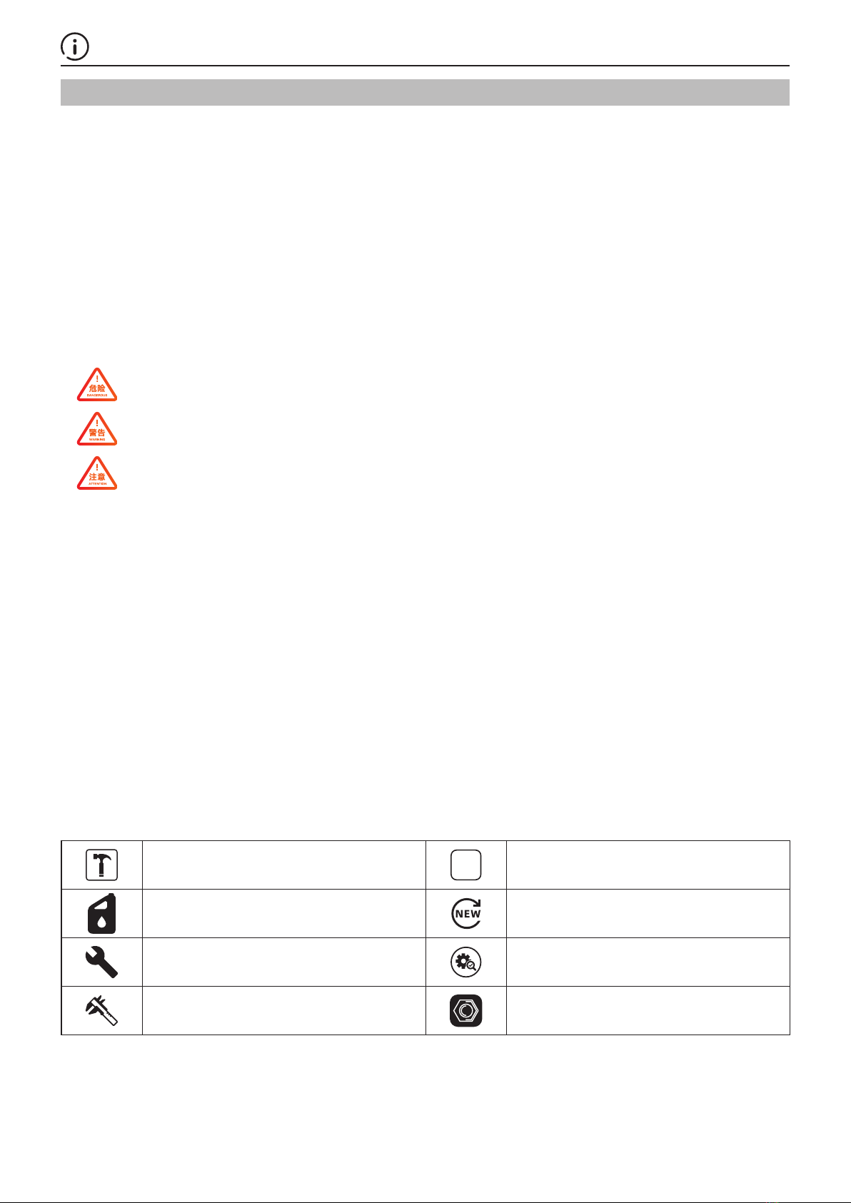
General Information
5
Vehicle Information
Product number:YD1800D-02
VIN Number LR4**************
Color: interstellar gray, aurora white, deep water blue, liquid silver, electro-optic bright red, interstellar brown
Configuration category Braking method Battery capacity Power-off switch
Basic configuration All disc brake 60V30AH /
Option I All disc brake, equipped with
distribution valve 60V30AH Sidestand switch
Motor type
VIN Number

General Information
6
SPECIFICATIONS
GENERAL SPECIFICATIONS
ITEM SPECIFICATIONS(3C) SPECIFICATIONS(E13)
DIMENSIONS
Length, width and height (mm) 1790x735x1220 1790x720x1210
Wheelbase(mm) 1270 1260
Seat height(mm) 763 763
Ground clearance(mm) 130 130
Curb weight(Kg) 95 83
Maximum weight capacity(Kg) 245 265
FRAME
Frame type Low-profile steel tube Low-profile steel tube
Front suspension Telescopic fork Telescopic fork
Front axle travel(m) 90 90
Rear suspension Swingarm Swingarm
Rear axle travel (m) 70 70
Front tire size 90/90-12 90/90-12
Rear tire size 100/80-12 100/80-12
Front tire brand Zhengxin Zhengxin
Rear tire brand Zhengxin Zhengxin
Front brake Hydraulic single disc Hydraulic single disc
Rear brake Hydraulic single disc Hydraulic single disc
Caster angle 23° 23°
Trail length(mm) 75 75
MOTOR
Motor model 12ZW6069325YE 12ZW6069325YE
Rated power(KW) 1.8 1.8
Peak power (KW) 2.4 2.4
Rated speed (rpm) 690 690
Peak speed (rpm) 740 740
Maximum torque(N·m) 105 105
CONTROLLER
Control method FOC FOC
Maximum input current(A) 45 45
Throttle turning angle sensing
method Hall sensor Hall sensor
BATTERY
Type Li-ion Li-ion
Voltage (V) 60 60
Voltage(Ah) 30 32
Total mass(Kg) 11 11
CONVERTER
Type DC-DC DC-DC
Output DC DC
Regulation method Inductance Inductance
CHARGER
Charging method Constant current and voltage Constant current and voltage
Input(V) 220 220(Europe)
Output(V) 70.5 70.5
Cooling method Natural cooling Natural cooling

General Information
7
FRAME & CHASSIS SPECIFICATIONS
FRONT WHEEL/SUSPENSION/STEERING
ITEM STANDARD LIMIT
Front fork
Front fork free length(mm) 409±2 /
Front fork stroke (mm) 90 /
Recommended oil Chuan Nan Shock Absorption
Oil CN3# /
Elastic coefficient K1 (N/mm)
Elastic coefficient K2 (N/mm)
Elastic coefficient K3 (N/mm)
K1=2
K2=3.9
K3=9.8
/
Travel(K1)
Travel(K2)
Travel(K3)
K1=36.2(Preload14.5)
K2=43.8
K3=24.5
/
Front fork oil capacity (ml) 102±2 /
Suspension method Telescopic /
Rear fork
Rear fork free length(mm) 320±2 /
Rear fork stroke (mm) 70 /
Recommended oil /
Elastic coefficient K1 (N/mm)
Elastic coefficient K2 (N/mm)
K1=10.9±0.872
K2=26.2±2.01 /
Travel(K1)(mm)
Travel(K2)(mm)
K1=50
K2=30 /
Rear fork oil capacity (ml) 76±2.5 /
Suspension method Integrated swing arm /
HYDRAULIC BRAKE(type 1)
ITEM STANDARD LIMIT
Front
Specified brake fluid DOT 3 or 4 brake fluid
Front brake disc thickness 4
Front main pump cylinder bore φ12.7
Front caliper cylinder bore φ32
Rear
Specified brake fluid DOT 3 or 4 brake fluid
Rear brake disc thickness 3.5
Rear main pump cylinder bore φ12.7
Rear caliper cylinder bore φ30.2
HYDRAULIC BRAKE(type 1 CBS linkage)
ITEM STANDARD LIMIT
Front
Specified brake fluid DOT 3 or 4 brake fluid
Front brake disc thickness 4
Front main pump cylinder bore φ12.7
Front caliper cylinder bore φ32
Rear
Specified brake fluid DOT 3 or 4 brake fluid
Rear brake disc thickness 3.5
Rear main pump cylinder bore φ15.87
Rear caliper cylinder bore φ27

General Information
8
ELECTRICAL SYSTEM SPECIFICATIONS
BATTERY/CHARGING SYSTEM
ITEM SPECIFICATIONS
BATTERY Cell configuration 60V30Ah
Short circuit protection
device
Main circuit Air switch 63A
Secondary circuit Fuse 20A
Charging circuit /
Torque
Each fastener should be tightened to the standard torque value except the fasteners specified torque value.
Standard tightening torque
Fastener name Thread diameter Tightening torque (N·m) Note
6.8(6) 8.8(8)
Bolts and nuts
M4 2~3 2~3 /
M5 3.5~6 4~7 /
M6 6~9 7~11 /
M8 16~21 18~25 /
M10 28~36 30~40 /
M10×1.25 32~40 35~45 /
M12 42~52 45~55 /
M12×1.5 48~56 50~60 /
M12×1.25 55~65 55~65 /
M14 60~70 60~70 /
M14×1.5 70~75 70~75 /
M14×1.25 80~85 80~85 /
Screws
M4 1.0~2.0 1.5~2.5 /
M5 3~5 3.5~5.5 /
M6 5~8 6~10 /
M8 15~20 16~23 /
M10 22~28 25~30 /
Note: The torque value of the screw is applicable to the screw on the cover. If it is used for the connection of iron parts, the
torque value of the bolt should be referred to.

General Information
9
CABLE & HARNESS ROUTING
Harness technical requirements:
1. The wiring harness is straight and beautiful without shaking;
2. There should be no damage to the outer skin of the wiring harness. Wrap the damaged parts with insulating tape;
3. Reduce the excess cable ties, and the remaining amount of the cable ties is 3-5mm.
Cable tie fixing
Wire clamp fixing
Distribution valve
Rear brake oil pipe
Brake oil pipe
(to the front caliper)
Central controller
USB connection
Brake oil pipe
(to the rear caliper)
Front brake oil pipe
Front lamp connection
GPS
4G module
DC-DC
converter
wiring
Main electrical
cable
Seat lock
cable
Solenoid valve
line
LED cable
Main electrical cable
Cable
Rear brake oil pipe
Main electrical cable
The main electrical
cable is fixed to the
stand pipe support

General Information
10
Right brake disconnect wire
Throttle grip wire
Left turn signal wire Right turn signal wire
Right combination switch cable
Fix the L/R combination switch and
brake switch to the stay on the handle pipe
Four holes (throttle grip)
Six-hole black (right combination switch)
Left brake disconnect wire
Left combination switch wire
Two holes (right brake handle)
Two holes (left brake handle)
Six-hole white (left combination switch)

General Information
11
Cable tie fixing
Wire clamping fixing
Wire hook fixing
Side stand switch wire
Seat Zipper Cable

General Information
12
Rear brake oil pipe
Motor line
Motor line
Motor line

General Information
13
Left turn signal wire
License plate light wire
Right turn signal wire
Main electrical cable
Wire hook fixing
License plate light wire
Left turn signal wire
Rigth turn signal wire

General Information
14
MAINTENANCE SCHEDULE
Please perform the pre-ride inspection in accordance with the maintenance schedule described in the maintenance schedule
table of the user manual.
■Check ▲Adjustment ♦Replace ●Lubricating
ITEMS EVERY
DAY 60 DAYS 180 DAYS 360 DAYS
1. Whether the handlebar rotation and steering parts are loose and
worn ■● ■● ●▲
2. Whether the pedal components are worn and whether they rotate
flexibly ■● ■● ♦
3. Whether the tire is properly inflated and whether the tire is worn ■♦
4. Whether the light bulb is on ■♦ ■♦ ■♦ ■♦
5. Whether the brake pad is worn ♦♦
6. Whether the rim is deflecting or deformed ■■♦
7. Whether the front fork of the frame is deformed ■■♦
8. Whether the fasteners are loose ■■▲
9. Is the brake good? ■■
▲■▲▲
♦
10. Whether the big horn is on ■▲♦
11. Whether the charger power cord is worn ■♦
12. The head tube, flat fork and shock absorber connected to the
frame ●
• The maintenance schedule for vehicles used in households shall be as specified in the table above.
• For non-domestic use (such as: business, commercial, corporate collective, group purchase, lease) vehicles,
the maintenance schedule shall be implemented according to the half of the above table.

Motor
15
Installation and disassembly …………………………………… 16
Fault diagnosis and maintenance ……………………………… 17
Tools for reparing ………………………………………………… 18

Motor
16
Installation and disassembly
75 N·m
Hexagon flange nut
M16
TT-type hexagon socket platform step screw
M8x20
Hexagon flange bolt
M8x35
Hexagon flange bolt (big head)
Combination with spring washer and
flat washerM8x35
Cross recessed pan head screw
M4x12
• Seat → Page 26
• Rear backrest → Page 27
• Foot pedal → Page 25
• Side cover → Page 28
Operating
order Operating name/parts number Number Note
1 Hexagon flange bolts M8×35 1 Separate the rear fork from the rear swing arm
2Hexagon flange bolt (big head) combined with
spring washer and flat washer M8×25 2Separate the rear caliper from the rear caliper
mounting bracket
3 Cross recessed pan head screws M4×12 1 Remove the rear swingarm cover
4 Hexagon flange bolt (big head) M6×16 2 Separate the motor from the rear swingarm

Motor
17
Fault diagnosis and maintenance
Motor abnormal noise
When troubleshooting the abnormal noise of the motor, please idle the motor first and confirm the source of the abnormal noise
again. After confirming the abnormal noise is from motor, proceed with the following procedure.
1. Check the motor bearings
Check whether the motor bearing lubrication operation is normal NO Replace bearing
YES
2. Check the inside of the motor
Check if there is foreign matter inside the motor?
YES
Clear foreign objects or replace the motor
The motor does not work
Before troubleshooting the motor does not work, please confirm whether the motor does not work because the side support is
not retracted (the side support switch is not closed). After confirming the elimination of the temple problem, proceed with the
following procedure.
1. Check the switch of parking switch
Turn off the power switch, and use the multimeter diode position to
check whether the P position switch is normal? NO switch of parking switch failure
YES
2. Check the brake power switch
Turn off the power switch, use a multimeter diode file to check
whether the brake power off switch is normal? NO Brake power switch failure
YES
3. Check the throttle grip
Confirm that the power supply voltage of the throttle grip is between
4.5-5.5V, use a multimeter DC voltage file to check whether the
signal line voltage of the speed-adjusting rotor is in the range of
0.8V-4.2V?
NO Throttle grip failure
YES
4.Motor Hall
Check whether the motor Hall connector is in good contact? NO Motor Hall connector failure
YES
5.Confirm the motor Hall supply voltage
Confirm that the power supply voltage of the motor Hall is between
4.5-5.5V, and gently turn the motor by hand. Does the UVW Hall
wire change between high and low levels to ground?
NO Motor Hall failure
YES
First replace the control to confirm whether the motor returns to
normal, if not, replace the motor.

Motor
18
Tools for reparing
Tool name Number Application
Gloves A pair Wear the motor and motor controller
during operation
Wrench One set Disassembly and use of nuts and bolts
Torque wrench One set Pre-tightening of nuts and bolts
Other manuals for C1S
1
This manual suits for next models
1
Table of contents
Other Yadea Motorcycle manuals
Popular Motorcycle manuals by other brands

Husqvarna
Husqvarna WR 125 2008 Workshop manual

KTM
KTM 1290 Super Duke R 2018 owner's manual

Husqvarna
Husqvarna TE 250 - 310 2011 I.E. Specifications - operation - maintenance

APRILIA
APRILIA RSV4 1100 Factory Service station manual

KTM
KTM 2013 1190 RC8 R JP owner's manual

BMW Motorrad
BMW Motorrad R 1200GS Adventure Rider's manual