Yaesu FT-100 Micro Mobile User manual

Yaesu FT-100 undocumented
Compiled by PA3GMP. Printed 4 April 2004

1
TABLE OF CONTENTS
M
ENU SETTINGS OVERVIEW
............................................................................................. 3
AT-11MP A
UTOTUNER
................................................................................................... 7
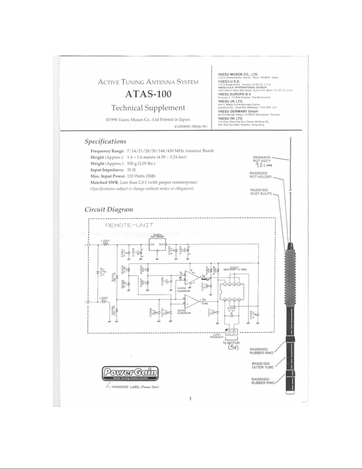
ATAS-100 A
UTOTUNING
................................................................................................ 8
WHAT'S IN THERE? ................................................................................................ 13
HOW DO I TAKE IT APART?.................................................................................. 14
HOW DO I PUT IT TOGETHER?............................................................................ 14
ATAS100 M
ANUAL
T
UNING
......................................................................................... 14
ATAS-1/ATAS-2 S
ETTINGS
......................................................................................... 15
ATBK100 G
ROUND
P
LANE
K
IT
.................................................................................... 15
CWID
WITH
ARTS........................................................................................................ 16
B
AND
D
ATA
P
IGTAIL
P
INOUT
........................................................................................ 16
CTCSS
AND MEMORY FUNCTIONS
................................................................................. 16
D
UPLEXERS
.................................................................................................................... 17
E
XTRA
B
ANDS
............................................................................................................... 17
F
ACTORY
M
ODIFICATIONS
............................................................................................. 17
Intermittent High SWR ICON ................................................................................... 17
Thermal modification................................................................................................ 20
FC-20 A
UTOTUNER
....................................................................................................... 24
F
IRMWARE
U
PGRADES
................................................................................................... 25
K
EYPAD
F
REQUENCY
E
NTRY
......................................................................................... 25
M
ANUAL
R
EVISIONS
...................................................................................................... 25
M
EMORY
P
ROGRAMMING
.............................................................................................. 26
M
IC ADAPTER
................................................................................................................ 27
M
IC
B
UTTONS
................................................................................................................ 28
M
ICROPHONE MODIFICATION
......................................................................................... 29
M
ODIFICATION FOR OUT
-
OF
-
BAND TRANSMISSION
........................................................ 29
O
UTPUT POWER
(
MEASURED IN AND OUT OF BAND
)....................................................... 31
P
OWER
C
ONNECTORS
/L
INE
F
ILTERS
.............................................................................. 34
PSK31/SSTV/
ETC
.
SOUNDCARD INTERFACE WITH THE
FT100...................................... 34
P
ROBLEMS WITH
FT100
RADIOS
.................................................................................... 37
R
EPEATER
O
FFSETS
....................................................................................................... 37
RF E
XPOSURE
................................................................................................................ 37
T
RANSMIT PROBLEMS ON
80/160M................................................................................ 38
S-M
ETER
A
NOMALIES
................................................................................................... 38
S
ATELLITE
O
PERATIONS
................................................................................................ 40
S
EPARATION KIT
(YSK100)........................................................................................... 41
S
ERIAL
N
UMBERS
.......................................................................................................... 41
S
IDETONE
/B
EEP
V
OLUME
A
DJUSTMENT
........................................................................ 41
S
QUELCH SETTINGS FOR
FM
AND
SSB .......................................................................... 42
S
TORING MEMORIES REMOTELY
..................................................................................... 42

2
SWR
METER INTERPRETATION
...................................................................................... 42
UP/DOWN
BAND SWITCHING
....................................................................................... 43
V/U MESFET
PRE
-
AMP ADJUSTMENT
........................................................................... 43
Y
AESU
C
ONTACTS
......................................................................................................... 44

3
Menu settings overview
Nr. Function Default Opt. 1 Opt. 2 Opt.
3 Opt. 4 Opt.
5 Remarks
1 Dial Pulse tuning rate 200 100 200
2 Beep key and buttons on on oFF
3 Scan Mode scan restart tinE StoP buSy tinE
4 Scan Speed dwell time 10 ms 10 100
5 Resume hold time 5
seconds 1 10
6 DW-time polling interval 5
seconds 1 10
7 DCS Code 104 codes 23 23 754
8 DCS
ENC/DEC normal or invert tn-rn tn-rn tn-rr tr-rn tr-rr
9 ARTS Beep beep mode ALL ALL rAng oFF
10 CW ID enable/disable oFF on oFF
11 ID up to 8 char.
12 Tone freq 39 tones 88.5 67 254
13 Dimmer set 63 dimmest oFF oFF 63
14 Peak Hold .5 sec hold oFF on oFF
15 Scope moni sweep mode oFF Cont Chec SgL oFF
16 DSP mic eq equalization oFF oFF 1 hi
cut 2 lo
cut 3 mid
only
17 DSP NR reduction level 7 1 16
18 DSP LPF high cut 6000 1000 6000
19 DSP HPF low cut 100 100 1000
20 BPF Width DSP CW filter 240 60 120 240
21 HF TX PO power 100% 0 100
22 50M TX PO power 100% 0 100
23 144M TX PO power 100% 0 100
24 430M TX PO power 100% 0 100
25 Mic Gain SSB-AM modes 50% 0 100
26 FM Mic Gain FM mode 50% 0 100
27 Comp Level SSB-AM modes 50% 0 100
28 AFSK Level input sensitivity 50% 0 100
29 APO Time hours to shutoff oFF oFF 1 2 3
30 TOT Time minutes 20 oFF 1 20
31 CW-W Filt optional wide
path oFF oFF on
32 AM/CW-N Filt AM or CW-N
filter oFF oFF 300 6_0
33 FM Dev deviation HF 2.5
KHz HF 2.5 2.5 5_0
34 AFSK mode mode-sideband PCt-F rtty-L rtty-U PCt-L PCt-U PCk-
F
35 RTTY Shift frequency shift 170 170 425 850
36 RTTY display offset nor nor Car
37 Packet rate 1200bps 1200 9600
38 Packet
display offset 2125 -3000 3000
39 Packet tone set for TNC 2125 1170 1700 2125 2210

4
40 HF RPT
SHIFT 10m shift 0.1 0 10MHz
41 50 RPT
SHIFT 6m shift 0.5 0 10MHz
42 144 RPT
SHIFT 2m shift 0.6 0 10MHz
43 430 RPT
SHIFT 440 shift 5 0 10MHz
44 144M ARS auto shift on-off on oFF on
45 430M ARS auto shift on-off on oFF on
46 Keyer Type keyer or paddle EL2 EL1 EL2 buG
47 Dot Size dot to space 10 0 125
48 Dash Size dash to space 30 0 125
49 CW-Delay semi QSK .5 sec 0 2.5
50 CW Pitch sidetone offset 700 400 500 600 700 800
51 CW Break-in QSK FULL FULL Seni
52 Keyer Speed 50 1 100
53 QSK Delay shifts output
times 5 0 30
54 VOX gain input sensitivity 50 0 100
55 Vox delay hang time .5 sec 0 2.5
56 SQL/RF gain mode of control SqL SqL rF
57 Lock mode lock mode diAL PAnEL diAL
58 AM&FM Click select knob
function on on oFF
59 Mic SW set mic buttons 1 1 2 3
60 NB Level IF noise
blanking 10 0 16
61 Tuner/ATAS device selection oFF AtAS-
1 AtAS-2 tunEr
62 RX LSB CAR Carrier point 0 -0.2 0.5
63 RX USB CAR Carrier point 0 -0.2 0.5
64 TX LSB CAR Carrier point 0 -0.2 0.5
65 TX USB CAR Carrier point 0 -0.2 0.5
66 5167.5 KHz Alaska
emergency oFF oFF on USA only
There is a second set of factory / service menu functions F01 to F59. WARNING:
changing these may reset all the memories. If you intend to make any changes, record all
the original values first. Most of these settings are unique to each radio and are
determined by using alignment procedures described in the FT100 Service Manual.
Do not change these values unless you are sure of what you are doing. To activate them
put the transceiver in VFO mode and turn it off. Press and hold the A,B,C keys; while
holding them in, press and hold in the [PWR] switch for 1/2 second to turn the transceiver
on. Now let go of all keys. Then press and hold the FUNC key for 1/2 second to get to the
menu and then rotate the select knob to get to a second menu (F01 to F59) after #66 or
before #01. When you turn the rig off and back on it returns to the normal menu.
Nr. Function Default (may vary) Set to: Remarks:
F01 144 RF GAIN 166
F02 430 RF GAIN 166

5
F03 HF RX IF G 98
F04 50 RX IF G 112
F05 144 RX IF G 108
F06 430 RX IF G 82
F07 S FULL SCALE 144
F08 SSB SQL 33
F09 FM N SQL 88
F10 FM RF SQL 56
F11 HF IC ALC 23
F12 V/UHFIC ALC 22
F13 HF PO 10W 26
F14 HF PO 50W 83
F15 HF PO 100W 123
F16 50 PO 10W 25
F17 50 PO 20W 45
F18 50 PO 50W 83
F19 50 PO 100W 123
F20 70 PO 10W 063 <<< 70 MHz
F21 144 PO 20W 65
F22 144 PO 50W 120
F23 430 PO 20W 139
F24 1.8 TX IF G 76
F25 3.5 TX IF G 69
F26 7 TX IF G 63
F27 10 TX IF G 63
F28 14 TX IF G 67
F29 18 TX IF G 71
F30 21 TX IF G 72
F31 24 TX IF G 72
F32 28 TX IF G 75
F33 50 TX IF G 104
F34 70 TX IF G 127
F35 144 TX IF G 97
F36 430 TX IF G 93
F37 ALC METER 196
F38 HF PO METER 170
F39 50 PO METER 172
F40 144 PO METER 105
F41 430 PO METER 63
F42 HF REV ALC 34
F43 50 REV ALC 34
F44 70 REV ALC 127 <<< 70 MHz
F45 144 REV ALC 173
F46 430 REV ALC 60
F47 SWR METER 141
F48 OVER HEAT 1 230
F49 OVER HEAT 2 235
F50 CW CAR LEVEL 166
F51 AM CAR LEVEL 113
F52 FM TX FREQ -32.47
F53 TRX LSB CAR 0.11
F54 TRX USB CAR -0.01

6
F55 blank
F56 blank
F57 DESTINA HF USA < JPN,JAIA,
STD,EU,FRAN,BEL,
GER,USA,AUS,UT
F58 DESTINA V/U USA < JPN,USA,
EU1,EU2,EU3,EU4,
AUS
F59 blank

7
AM Settings
Gary Mitchelson, N3JPU, has done some interesting tests with the AM settings and found
some settings that work much better than the defaults. The parameters that sound the best
are: PO set to 25, Mic gain to 40 to 50 and Carrier Level set to 225 (F51 menu). You can
hear a sample of his testing at: http://mywebpages.comcast.net/n3jpu/
Most owners who have had difficulties with AM audio quality have reported that the 6k
HZ option AM filter (p/n XF117A) is an absolute necessity for both transmitting and
receiving in AM mode.
The following procedure will result in excellent AM transmit operation with the FT-
100(D). The User's Manual does not include any guidance regarding this. For this
discussion I assume HF AM operation.
• Install the 6 kHz filter. You need the filter in order to have proper AM operation.
• Turn on the unit while holding in the A, B and C buttons in order to access the
sub-menu "F" functions.
• Place the unit in AM mode.
• Set the MIC gain setting to 17 (seventeen).
• Using the F51 function, key the mic and set your un-modulated carrier output
power to 25 Watts, no higher.
• That's it. You should now have 100 Watts PEP on voice peaks which is 6 dB (4
times) the un-modulated carrier power.
Extra hints: Set function F15 to 170 in order to avoid non-linear compression on voice
peaks. But note the original setting and restore F15 to the factory setting when you
operate SSB and CW. You should have 100 Watts output in CW mode when F15 is
properly set.
You can use the speech processor during AM operation but you must not exceed a setting
of 17 when using it, just as with non-processed operation. The PROcessor control is
simply a second MIC gain control which over-rides the MIC gain control setting
whenever you enable the PROcessor. The FT-100(D) actually does not allow you to vary
the compression percentage.
AT-11MP Autotuner
Some owners have opted to purchase the AT-11MP auto tuner from LDG Electronics.
This is available in either a kit or assembled format and does not suffer from the
CAT/FC-20 limitations.
There is an accessory for the FT100/D called the OTT or 'One Touch Tune' available
from W4RT.com that allows you to use the 'Tune' button on the FT100 to control the
tuning function of the AT11 directly from the FT100. It also allows you to maintain the
CAT compatibility which is something you normally lose with the FC-20 autotuner.

8
ATAS-100 Autotuning
The tuning behavior of the ATAS can cause confusion unless you understand the
algorithm it follows to find a good position. Normally, if the ATAS is installed correctly
and it successfully autotunes itself, it will always go in the correct direction when you
press in the TUN button for 1/2 second once it has found its first good match. However, it
the ATAS cannot find a match, it will run all the way to one end, turn around, and start
over. This process can take a while since the antenna runs 'open loop' when it loses its
position. Since it doesn't know which position the antenna is in unless it makes its own
successful match, it needs to be sure it has gone all the way to the end before reversing,
which can take a very long time.
Anytime it is not sitting right where it found a match all by itself, it can end up starting
out in the wrong direction next time. Examples would be if you manually do even just a
little fine tuning, or if you interrupt autotuning and change bands. Then the rule is very
simple: it starts the next autotune by going in the last direction it was going in, which is
not necessarily right. If it's going in the wrong direction, the antenna will move all the
way to a stop and then it will have to turn around and start over again after a long delay.
If you recognize that it's going in the wrong direction, you can avoid the long delay by
aborting the autotuning process by hitting the TUN key momentarily, then manually
move the antenna just a little (with the PTT and up or down keys) in the correct direction,
and then recommence with the autotuning procedure.

9
ATAS-100 Disassembly

10

11

12

13
Disclaimer:
The following procedures can possibly void your warranty.
WHAT'S IN THERE?
(And a little on how it works)
The stainless steel whip is mounted on top of a loading coil (under the rubber boot). The
coil consists of copper wire wound around a "grooved" fiberglass rod. Part of the reason
the antenna is guaranteed to work on 40,20,15 and 10m HF bands but not on 12,17 and
30m is that the spacing on the coil is wider at the resonant points on the coil on the
"primary" bands allowing easier tuning.
The loading coil slips into the "body" of the antenna where spring loaded contacts make
the necessary connections. At the base of the coil and rod is a Teflon disk that makes
sliding contact with the inside of the tube and is threaded for the brass "screw" rod that
raises and lowers the coil.
About 7" below the contacts is the motor and clutch assembly (at the middle rubber
cover). Two wires run from the motor to the controller board that is mounted on top of
the base unit.
The base (matching unit) consists of a chromed top cap which includes the mount for the
motor controller board. Below this is a 3" black plastic tube that forms an insulator. At
the bottom is the threaded chromed base cap that is where the SO-239 connector screws

14
in. This base assembly is secured with pins and would be hard to dissemble without
damaging.
Inside this is an RF choke coil (I'm not sure if it is air wound or on a torrid) that makes
this whole antenna DC grounded. This protects the radio from damage from whip contact
with power sources, static build up, etc. The coil also helps with matching the antenna
and contributes to the high Q of the design.
Connected to this is a capacitor that leads to the center pin on the SO-239 receptacle in
the base. This capacitor is also part of the "broad band" matching network.
HOW DO I TAKE IT APART?
1. Extend the antenna fully (40m).
2. Remove from vehicle and take it to a clean work surface.
3. Remove the whip for ease of handling.
4. Slide up the 2 rubber covers exposing the screws.
5. Remove the 3 lower screws above the base.
6. CAREFULLY remove the base by gently pulling down while using a slight
rocking motion (the resistance is from a O ring).
7. Carefully withdraw the base assembly while noting the routing of the motor wires.
8. Unplug the micro connector from the motor controller board (the red and black
wires that leads to the motor-clutch assembly), and set the base aside.
9. Mark on the shaft the location of the bottom of the boot, then slide the boot
upwards exposing the loading coil.
10. Remove the remaining 6 screws on the antenna.
11. Carefully slide up the loading coil which also removes the motor-clutch assembly
(be careful with the alignment pin).
There is more than can be disassembled, but the above steps are all that is needed for
most maintenance and repairs. While you're in there, clean the moving surfaces up and oil
with a light oil (like mineral oil) that won't harm plastics while taking care not to
contaminate the contacts, coils and connections.
HOW DO I PUT IT TOGETHER?
1. Basically reverse the above procedure.
2. Be careful to make sure the alignment pin (about 7" long) from the loading coil to
the motor-clutch assembly is in place.
3. Pay special attention to the routing of the motor wires to prevent pinching
between the motor controller board and motor-clutch assembly.
ATAS100 Manual Tuning
The ATAS100 can be tuned up and down manually by holding in on the PTT switch and
using the UP/DOWN keys on the front of the radio. If you thought it meant the
UP/DOWN keys on top of the hand mic, you're not alone, as several others have made
the same mistake and the manual does not specify which UP/DOWN keys to use. It has
been noted that the P1/P2 keys on the mic will cause the antenna tune icon to come on if
you push them while holding the PTT, but they do not actually move the antenna.

15
ATAS-1/ATAS-2 Settings
Menu item 61 is has several settings for controlling the way the ATAS100 antenna
works. In the user manual, there are several errors describing this function. On page 14,
the instructions are correct and the easiest way to remember the correct settings are:
ATAS-1 = one antenna ; ATAS-2 = two separate antennas. In other words, if you're using
the ATAS100 on all bands (with a duplexer), choose ATAS-1. If you are using the
ATAS100 for HF only and a separate antenna for VHF/UHF, use ATAS-2. Page 62 in the
manual is backwards from this as is page 94 which recommends that a duplexer is
required with ATAS-2. The newer manuals may have corrected these errors but as of
manual revision E08981003 the mistakes were still present.
Another user noticed that when either of these selections are made, the radio will not
transmit on the 80 or 160 meter bands so don't forget to switch menu item 61 to OFF (or
to Tuner) when you switch from the ATAS100 to another antenna.
ATBK100 Ground Plane Kit
The ATBK100 is a kit consisting of 3 ground radials for the ATAS100 intended to make
it suitable for use as a base antenna. Although there is no information available on the
Yaesu website about the ATBK100, this US$90 kit is supposed to supply a ground plane
for the 50 MHz, 144 MHz, and 430 MHz bands. One owner responded that he was able
to get the antenna to work on other HF bands by adding two 20' lengths of wire to the
ATBK100 to act as a counterpoise.
Audio Settings (improving transmitted audio performance)
Bill, N4XEO, has contributed the following advice for those who are not satisfied with
their audio reports. First, make sure the rig's chassis is grounded to the frame of the
vehicle and that the rig is powered directly off the battery with minimal voltage loss
through the power cable. Secondly, make sure that the voltage is sufficient for the rig.
The specifications call for 13.8V DC and so if you're not running the engine, it's likely
that your voltage won't run the rig correctly for very long. This will be apparent when
operating with the engine off as the battery voltage begins to sag down around 12V.
Here are some of the settings Bill recommends that have worked for him and others to
improve the audio:
Menu Item Description Value
25 Mic Gain (for SSB and AM
modes) 40
26 FM Mic Gain 45
27 Compression Level 40
33 FM Deviation 5
62 RX LSB Carrier +050
63 RC USB Carrier +050
64 TX LSB Carrier -200
65 TX USB Carrier -200

16
CWID with ARTS
The CWID feature appears to have a bug. It sends out the 'W' as a 'U' in Morse code. The
CWID feature, when enabled, transmits a CW identifier every 10 minutes when the radio
is operating in ARTS mode. Here is a set of instructions on how to test if your radio is
affected:
Go to menu item 11 and enter a CW ID string with some W's in it. To do this, press
Select knob and use the main dial to select the characters. Press the Select knob to
advance one character. Program all 8 characters using the Select button to advance. When
you get them all programmed, press Select again and the radio will playback the ID
you've stored. Use a tape recorder unless you think you can copy comfortably at 35-40
wpm. If you want to hear it on the air, proceed with the following instructions.
Go to menu item 10 and enable the CW id during ARTS operation.
Set the radio to a clear simplex FM frequency.
Press the FUNC key until you get to screen 3 which shows TON DCS and ART. Enable
ART.
Listen on another radio. The DCS code will be sent every 15 seconds and the CW ID will
occur every 10 minutes. Again, use a tape recorder, as the ID comes across at about 35-40
wpm. I have a little recorder that will allow me to record at 2.4 cm/sec and play back at
1.2 cm/sec so I can listen to the CW at a more comfortable 18-20 wpm.
Band Data Pigtail Pinout
The Band Data pigtail can control a VL-1000 amplifier when set internally to control an
amplifier. The normal mode is for the CAT/Tuner function, but it can be rearranged with
an internal jumper (shown on page 19 of the manual) to control an amplifier. If you're
curious about how the signals work in that mode, the table below shows the logic
depending on the band selected. The images to help explain this better are shown here.
Yaesu FT-100D Band Data Output map H=4.4 vdc L=0 vdc
Band 1.8 3.5 7 10 14 18 21 24 28 50 144 440
A H L H L H L H L H L H L
B L H H L L H H L L H H L
C L L L H H H H L L L L H
D L L L L L L L H H H H H
CTCSS and memory functions
Storing CTCSS frequencies in memory along with frequencies is a bit tricky. When
putting frequencies into memory from the VFO you must have encode on and the display

17
must show ENC for the CTCSS tone to go into memory. If the main display does not
show ENC when the frequency is put into memory, the CTCSS setting is not stored.
Duplexers
The ATAS100 is designed to tune on all the bands on which the radio transmits including
2m and 70cm. This requires a duplexer like the Diamond MX62M or the Comet CF706
to connect the VHF/UHF and HF pigtails together. (The actual cross-over
frequency between the pigtails is 70.5Mhz.) However, many people prefer to use a
separate antenna for the VHF/UHF bands since those antennas typically cost about the
same price as a duplexer and usually have some gain whereas the ATAS100 has no gain
on VHF/UHF. Also, with separate antennas you don't have to worry about retuning when
switching between VHF/UHF and HF.
A consideration when using a duplexer is that the DC voltage for tuning the ATAS-100 is
supplied through the HF pigtail. Therefore, this pigtail must always be connected to the
ATAS for tuning purposes. Also, it must not be capacitively coupled inside the duplexer
or it will block the DC motor control voltage.
Extra Bands
You may have noticed two extra bands appear while moving through the normal ham
bands using the up/down keys. Apparently, the rig remembers an extra band for HF and
another for V/U portions of the radio. If you tune outside a normal ham HF band either
accidentally or intentionally, you'll notice that this band will now appear in a list of bands
as you use the up/down keys. The same is true for the V/U side of the radio. For example,
if you tune to the weather band at 162 Mhz, it will appear in the list between the 2M and
70cm bands. Short of resetting the radio, there's no way to get rid of these bands. Some
have elected to move them to the end of the list by tuning a frequency below 160M or
above 70cm so that they don't appear inside the list of bands.
Factory Modifications
There are two common modifications retrofitted to the FT100s manufactured prior to
2001. These include the fixes for the Intermittent High SWR ICON problem and the
VHF/UHF thermal sensor modification to enable the fans in the V/U receive mode.
Although there had been reports that new radios included the SWR mod, the mod has
been through several iterations and it's possible that even radios purchased today do not
include the 'final' mod with the screws, but rather just the copper tape held on with
adhesive.
Intermittent High SWR ICON
Some owners have had trouble with the HIGH SWR Icon appearing while attempting to
transmit on certain bands. The most common advice is to make sure that the antenna
mount and radio are properly grounded via some heavy braided material to the vehicle
chassis. Some owners have had success in using clamp-on ferrites with the separation kit

18
cable wrapped several times around the ferrite to block common mode current from
getting back into the rig. Ten meters seems particularly prone to the problem. Changing
the feedline length has also helped in some cases, but this seems to move the problem
around more than solving it at the root cause. Also, some owners have found that fixing
the grounding of the LPF board by adding solder around the screw holes and in some
cases tightening the screws or adding star washers was sufficient to make their grounding
problems go away.
However, there is a very effective modification that has worked in every case. The mod
involves fixing the grounding in the coax sockets on LPF of the radio and a metal shield
on the Main Unit. A degradation in the LPF grounding can cause the rig to break into
oscillation (even at lower power) causing the HIGH SWR icon to appear intermittently
even with a good antenna match on the higher HF bands. The mod will eliminate this
oscillation and the high SWR reports. Here are a few pictures of the factory installed
mod. The adhesive copper tape has been replaced screws or clamps that are attached to
the casting web. Note that on the upper strap, they have added a screw and the lower strap
was added and soldered to the shield as well as the coax and also screwed to the casting.
Before the factory mod

19
After the factory mod
Other manuals for FT-100 Micro Mobile
4
Table of contents
Other Yaesu Transceiver manuals

Yaesu
Yaesu FT-950 Technical manual

Yaesu
Yaesu FT-101EE User manual

Yaesu
Yaesu FT-1500M User manual

Yaesu
Yaesu VX-120 Series User manual

Yaesu
Yaesu FT-DX100 User manual

Yaesu
Yaesu FTM-400DR/DE Manual

Yaesu
Yaesu FT-4VR User manual

Yaesu
Yaesu FTA-750 Spirit User manual

Yaesu
Yaesu FTdx3000 Series Manual

Yaesu
Yaesu FT-5200 User manual

Yaesu
Yaesu FT-747GX User manual

Yaesu
Yaesu FT-480R Manual

Yaesu
Yaesu FT-710 User manual

Yaesu
Yaesu FT-817ND User manual

Yaesu
Yaesu FTM-7250DR Manual

Yaesu
Yaesu FRG-9600 User manual

Yaesu
Yaesu FT-757GX II User manual

Yaesu
Yaesu FTDX-9000MP User manual

Yaesu
Yaesu FT-60R User manual

Yaesu
Yaesu FT-7800R User manual