Yaesu FT-897D User manual

HF/VHF/UHF
ALL MODE TRANSCEIVER
FT-897D
Operating Manual
VERTEX STANDARD CO., LTD.
4-8-8 Nakameguro, Meguro-Ku, Tokyo 153-8644, Japan
VERTEX STANDARD
US Headquarters
10900 Walker Street, Cypress, CA 90630, U.S.A.
YAESU EUROPE B.V.
P.O. Box 75525, 1118 ZN Schiphol, The Netherlands
YAESU UK LTD.
Unit 12, Sun Valley Business Park, Winnall Close
Winchester, Hampshire, SO23 0LB, U.K.
VERTEX STANDARD HK LTD.
Unit 5, 20/F., Seaview Centre, 139-141 Hoi Bun Road,
Kwun Tong, Kowloon, Hong Kong

Contents
CAT

Page 1FT-897D OPERATING MANUAL
The FT-897D is a rugged, innovative multiband, multi-
mode portable transceiver for the amateur radio MF/HF/
VHF/UHF bands. Providing coverage of the 160-10 meter
bands (include the 60 m band: USA version) plus the 6 m, 2
m, and 70 cm bands, the FT-897D includes operation on
the SSB, CW, AM, FM, and Digital modes, yielding the most
comprehensive performance package available for field op-
eration.
Designed for use from (1) an external DC power source,
(2) internal battery (requires optional FNB-78 Ni-MH bat-
tery pack), or (3) AC power source (requires optional FP-
30 External AC Power Supply), the FT-897D provides 100
watts of power output from a 13.8-Volt external power sup-
ply or AC operation. When using the optional FNB-78 Ni-
MH Battery Pack, the FT-897D automatically switches to
20 Watts (430 MHz:10W) of output power.
The multi-function Liquid-Crystal Display includes at-
tractive backlighting, which may be disabled for battery con-
servation. The display includes bar-graph indication of power
output, ALC voltage, SWR, and modulation level. Also in-
clude are a number of operating status icons, as well as the
function displays for the three operating function keys (A,
B, and C).
INTRODUCTION
Among the advanced features of the FT-897D are many
incorporated only in large base-station transceivers. These
include Dual VFOs; Split-Frequency operation; Digital Sig-
nal Processing (Bandpass Filtering, Noise Reduction, Notch,
and Microphone Equalizer); IF Shift; Clarifier (“R.I.T.”);
IF Noise Blanker; AGC Fast/Slow/Auto/Off selection; RF
Gain and Squelch control; IPO (Intercept Point Optimiza-
tion) and a receiver front-end Attenuator; Built-in High Sta-
bility Reference Oscillator; AM Aircraft reception; AM and
FM Broadcast reception; U.S. Weather Band reception;
VOX; Built-in Electronic Keyer; Adjustable CW Pitch;
Automatic FM Repeater Shift (ARS); Built-in CTCSS En-
coder/Decoders; ARTS™ (Auto-Range Transponder Sys-
tem); Smart Search™ Automatic Memory Loading System;
Spectrum Scope; 200 Memories plus Home Channels and
Band-limiting Memories; Alpha-Numeric Labeling of
Memories; Automatic Power-Off (APO) and Time-Out Timer
(TOT) functions; Computer Interface capability; and Clon-
ing capability.
We urge you to read this manual in its entirety, so as to
gain a full understanding of the amazing capability of the
exciting new FT-897D Transceiver.

Page 2 FT-897D OPERATING MANUAL
General
Frequency Range: Receive: 0.1-56 MHz, 76-108 MHz, 118-164 MHz, 420-470 MHz
Transmit: 160 - 6 Meters (USA: includes 60 meters), 2 Meters, 70 Centimeters
(Amateur bands only)
5.1675 MHz (Alaska Emergency Frequency: USA only)
Emission Modes: A1 (CW), A3 (AM), A3J (LSB/USB), F3 (FM),
F1 (9600 bps packet), F2 (1200 bps packet)
Synthesizer Steps (Min.): 10 Hz (CW/SSB), 100 Hz (AM/FM/WFM)
Antenna Impedance: 50 Ohms, Unbalanced (M)
Operating Temp. Range: +14 °F to +140 °F (–10 °C to +60 °C)
Frequency Stability: ±0.5 ppm/1 hour @25 °C, after warmup
Supply Voltage: Normal: 13.8 VDC ±15 %, Negative Ground
FNB-78 (Ni-MH Battery Pack): 13.2 V (Option)
Current Consumption: Squelched: 600 mA (Approx.)
Receive: 1 A
Transmit: 22 A
Case Size (W x H x D): 7.87” x 3.15” x 10.3” (200 x 80 x 262 mm)
Weight (Approx.): 8.6 lb (3.9 kg) (w/o Ni-MH battery, antenna, Microphone)
Transmitter
RF Power Output (@13.8 V DC): SSB/CW/FM AM Carrier
160- 6 Meter: 100 W 25 W
2 Meter: 50 W 12.5 W
70 Centimeter: 20 W 5 W
Modulation Types: SSB: Balanced Modulator, AM: Early Stage (Low Level), FM: Variable Reactance
FM Maximum Deviation: ±5 kHz (FM-N: ±2.5 kHz)
Spurious Radiation: –50 dB (1.8-29.7 MHz)
–60 dB (50/144/430 MHz)
Carrier Suppression: >40 dB
Opp. Sideband Suppression: >50 dB
SSB Frequency Response: 400 Hz-2600 Hz (–6 dB)
Microphone Impedance: 200-10k Ohms (Nominal: 600 Ohms)
Receiver
Circuit Type: Double-Conversion Superheterodyne (SSB/CW/AM/FM)
Superheterodyne (WFM)
Intermediate Frequencies: 1st: 68.33 MHz (SSB/CW/AM/FM); 10.7 MHz (WFM)
2nd: 455 kHz
Sensitivity: SSB/CW AM FM
100 kHz-1.8 MHz –32 µV –
1.8 MHz-28 MHz 0.2 µV 2 µV –
28 MHz-30 MHz 0.2 µV 2 µV 0.5 µV
50 MHz-54 MHz 0.125 µV 1 µV 0.2 µV
144/430 MHz 0.125 µV –0.2 µV
(SSB/CW/AM = 10 dB S/N, FM = 12 dB SINAD)
Squelch Sensitivity: SSB/CW/AM FM
100 kHz-1.8 MHz ––
1.8 MHz-28 MHz 2.5 µV –
28 MHz-30 MHz 2.5 µV 0.32 µV
50 MHz-54 MHz 1 µV 0.16 µV
144/430 MHz 0.5 µV 0.16 µV
Image Rejection: HF/50 MHz: 70 dB, 144/430 MHz: 60 dB
IF Rejection: 60 dB
Selectivity (–6/–60 dB): SSB/CW: 2.2 kHz/4.5 kHz
AM: 6 kHz/20 kHz
FM: 15 kHz/30 kHz
FM-N: 9 kHz/25 kHz
S
z/2.0 kHz
CW (option YF-122CN installed): 300 Hz/1.0 kHz
AF Output: 2.5 W (@4 Ohms, 10% THD or less)
AF Output Impedance: 4-16 Ohms
Specifications are subject to change without notice, and are guaranteed within the amateur bands only.
SPECIFICATIONS

Page 3FT-897D OPERATING MANUAL
SUPPLIED ACCESSORIES
Hand Microphone MH-31A8J
DC Power Cord
Operating Manual
Warranty Card
AVAILABLE OPTIONS
FP-30 External AC Power Supply
FP-1030A External AC Power Supply (25A)
FP-1023A Compact Power Supply (23A; U.S.A. only)
FNB-78 Ni-MH Battery Pack (13.2 V, 4500 mAh)
PA-26B/C/U Ni-MH Battery Charger
CD-24 Ni-MH Battery Charger Adapter
YF-122S Collins SSB Filter (2.3 kHz/4.7 kHz: -6 dB/-66 dB)
YF-122C Collins CW Filter (500 Hz/2 kHz: -6 dB/-60 dB)
YF-122CN Collins CW Filter (300 Hz/1 kHz: -6 dB/-60 dB)
FC-30 External Automatic Antenna Tuner
ATAS-25 Active-Tuning Antenna System
ATAS-100 Active-Tuning Antenna System
ATAS-120 Active-Tuning Antenna System
ATBK-100 VHF/UHF Antenna Base/Counterpoise Kit
MMB-80 Mounting Braket
VL-1000 Solid-State Linear Amplifier
MD-200A8X Desktop Microphone
MH-36E8J DTMF Microphone
MH-59A8J Remote Control Microphone
CT-62 CAT Interface Cable
CT-39A Packet Cable
CT-58 BAND DATA Cable
ACCESSORIES & OPTIONS

Page 4 FT-897D OPERATING MANUAL
POWER CONNECTIONS
The FT-897D is designed use from (1) an external DC power source, (2) internal battery (requires optional FNB-78 Ni-MH
battery pack), or (3) AC power source (requires optional FP-30 Internal AC Power Supply).
External DC power source operation
INSTALLATION
The DC power connector for the FT-897D must only be
connected to a DC source providing 13.8 Volts DC (±15%),
and capable of at least 22 Amperes of current. Always ob-
serve proper polarity when making DC connections:
The Red DC power lead connects to the Positive (+)
DC terminal; and the Black DC power lead connects
to the Negative (–) DC terminal.
In mobile installations, noise pickup may be minimized by
connecting the DC cable directly to your vehicle’s battery,
rather than to the ignition switch or “accessory” circuitry.
Direct connection to the battery also provides the best volt-
age stability.
Tips for Successful Mobile Installations:
ÌBefore connecting the DC cable to the battery, measure
the voltage across the battery terminals with the engine
running fast enough to show a charge. If the voltage is
above 15 Volts, the vehicle’s voltage regulator should
be adjusted to reduce the charging voltage to 14 Volts or
lower.
ÌRoute the DC cable as far away from the ignition cables
as possible.
ÌIf the DC cable is not long enough, use #12 AWG (mini-
mum) stranded, insulated wire to extend it. Be certain to
solder the connections at the splice securely, and pro-
vide ample insulation for the soldered splice (heat shrink
tubing plus black electrical tape work well).
ÌCheck the battery terminal connections frequently to be
sure they are tight and not corroded.
ÌWhen operating with the vehicle turned off, or operating
from a stand-alone car battery (in a camp site, etc.), be
mindful of the minimum operating voltage (11.73 Volts)
for the FT-897D. If the battery is not charged sufficiently
to maintain at least 11¾ Volts at the radio, erratic opera-
tion or shut-down may occur.
Caution
Permanent damage can result if improper supply volt-
age, or reverse-polarity voltage, is applied to the FT-
897D. The Limited Warranty on this transceiver does
not cover damage caused by application of AC voltage,
reversed polarity DC, or DC voltage outside the speci-
fied range of 13.8V ±15%. Never attempt to connect
the FT-897D to a 24 Volt battery system.
When replacing fuses, be certain to use a fuse of the
proper rating. The FT-897D requires a 25A fast-blow
fuse.

Page 5FT-897D OPERATING MANUAL
INSTALLATION
AC power source operation (requires optional FP-30 AC power supply)
POWER CONNECTIONS
For base station installations, Yaesu recommends the use of
the FP-30 AC power supply, which is designed to clamp
onto the FT-897D.
Installation
1. Turn the transceiver’s power off, and disconnect all
cables from the transceiver.
2. Remove the six screws (three screws on bottom side and
rear side), then lift off the bottom cover (Figure 1 and 2).
3. Attach the FP-30 to the bottom of the FT-897D, then
affix it in place with the six screws removed in the above
steps (Figure 3).
4. Connect the 6-pin Molex plug from the FP-30 to the
INPUT jack on the rear panel of the FT-897D (Figure
4).
5. Make sure that your AC voltage is correct and that the
FP-30 POWER switch is set to Off; connect the AC
power cable between the INPUT jack on the rear panel
of the FP-30 and a nearby AC wall outlet.
Operation
1. To turn the transceiver on, turn on the POWER switch
on the FP-30 before turning on the POWER switch on
the FT-897D.
2. To turn the transceiver off, turn off the POWER switch
on the FT-897D before turning off the POWER switch
on the FP-30.
When you do not use the FP-30 with the FT-897D
for a long time, disconnect the AC plug from the AC
wall outlet.
Figure 1
Figure 2
Figure 4
POWER Switch
Figure 3
AC Input Voltage Selection (U.S.A. Users only)
ÌBefore moving the AC range switch, disconnect the FP-30’s AC Power
Cable from the AC line outlet, then wait 10 minutes to allow the power
supply’s electrolytic capacitors to discharge (electrical shock hazard!).
ÌPeel off the label on the side of the FP-30.
ÌMove the AC range switch to the “115” position for operation from
100-120 VAC, or to the “230” position for operation from 200-240 VAC.
ÌAlways uses the 10 A Fuse in the fuse holder on the rear panel whether
operate on 100-120 VAC or 200-240 VAC. Do not use the improper
fuse.
Warning: Our Warranty does not cover damage caused by improper supply voltage nor use of an improper fuse.
Peel off the label

Page 6 FT-897D OPERATING MANUAL
DC Power Cord
Internal battery operation (requires optional FNB-78 Ni-MH battery pack)
INSTALLATION
POWER CONNECTIONS
The optional FNB-78 Ni-MH Battery Pack provides 13.2
Volts of DC power for your FT-897D, with a maximum ca-
pacity of 4500 mAh (you may install the two FNB-78 into
the FT-897D, in this time, maximum capacity is 9 Ah!).
A fully charged set of FNB-78 Ni-MH Battery Pack should
provide approximately 4 hours of reception under typical
conditions.
Installation
1. Turn the transceiver’s power off, and disconnect all
cables from the transceiver.
2. Remove the six screws (three screws on bottom side and
rear side), then lift off the bottom cover (Figure 1 and 2).
3. Insert the FNB-78 into the battery compartment “A” or
“B”on the bottom of the radio so that the battery’s mount-
ing tab is aligned with the mounting hole on the radio’s
chassis (Figure 3).
4. Connect the 3-pin connector from the FNB-78 to the
battery jack on the radio’s chassis, corresponding to the
label (“A” or “B”) of the battery compartment to which
the FNB-78 is installed (Figure 3).
5. Remove the plastic cap, which is same label (“A” or “B”)
of the battery compartment witch is the FNB-78 installed,
from the to bottom cover, before turning the plastic cap
so that the small project of the cap is aligned with the
slot of the bottom cover (Figure 2).
6. Replace the bottom cover and its six screws.
Charging
Charging of the FNB-78 requires the use of the optional
CD-24 Charge Adapter.
1. Turn the radio off.
2. Connect the cable plug from the DC Power supply into
the INPUT jack on the CD-24 Charge Adapter, then in-
sert the cable plug from the CD-24 into the “CHG-A”
or “CHG-B” jack on the rear of the radio.
3. The “BATT-A” or “BATT-B” indicator on the front panel
of the FT-897D will glow red (Charging) while the bat-
tery is being charged. When charging is completed, the
red LED indicator will turn to off (Fully Charged).
A fully-discharged pack will be charged completely in
about four hours.
4. Unplug the cable from the CHG terminal, then discon-
nect the CD-24 from the DC Power supply.
Operation
Before turning the radio on, select the battery (“A” or “B”)
to be used by setting the top panel’s A-Bswitch as appropri-
ate.
A
AB
B
Figure 1 Figure 2
Figure 3
Connector “A”
Connector “B”
Plastic Cap
CHG jack on the rear of the radio
CD-24
AC Power Supply

Page 7FT-897D OPERATING MANUAL
INSTALLATION
GROUNDING
The provision of an effective ground system is important in
any successful communications station. A good ground sys-
tem can contribute to station efficiency in a number of ways:
ÌIt can minimize the possibility of electrical shock to the
operator.
ÌIt can minimize RF currents flowing on the shield of the
coaxial cable and the chassis of the transceiver which
may cause interference to nearby home entertainment
devices or laboratory test equipment.
ÌIt can minimize the possibility of erratic transceiver op-
eration caused by RF feedback or improper current flow
through logic devices.
An effective earth ground system may take several forms;
for a more complete discussion, see an appropriate RF engi-
neering text. The information presented below is intended
only as a guideline.
Inspect the ground system – inside the station as well as
outside – on a regular basis so as to ensure maximum per-
formance and safety.
Mobile Station Grounding
Although satisfactory grounding in most installations will
be achieved via the DC cable’s negative lead and the an-
tenna system’s coaxial cable shield, it is often recommended
that you provide a direct ground connection to the vehicle
chassis at the mounting location of the transceiver (installa-
tion using the optional MMB-80 Mounting Bracket will ac-
complish this, if the MMB-80 itself is mounted to the
vehicle’s chassis). Due to unexpected resonance which may
naturally occur in any location, improper communication
system performance may result from insufficient ground-
ing. These symptoms may include:
ÌRF feedback (resulting in distortion on your transmitted
signal);
ÌUnintended frequency change;
ÌBlinking or blanking of the frequency display;
ÌNoise pickup; and/or
Ì
ons may occur in any communica-
tions installation. The FT-897D includes extensive filtering
designed to minimize the chance of such problems; how-
ever, random currents set up by insufficient RF grounding
can nullify such filtering. Bonding the rear panel Ground
lug of the FT-897D transceiver to the vehicle or vessel’s
ground system should clear up any such difficulties.
Vertex Standard does not recommend the use of “on glass”
mobile antennas unless the shield of the coaxial cable is se-
curely grounded near the feedpoint of the antenna. Such
antennas frequently are responsible for the ground-related
difficulties described above.
Base Station Earth Grounding
Typically, the ground connection consists of one or more
copper-clad steel rods, driven into the ground. If multiple
ground rods are used, they should be configured in a “V”
configuration, and bonded together at the apex of the “V”
which is nearest the station location. Use a heavy, braided
cable (such as the discarded shield from type RG-213 co-
axial cable) and strong cable clamps to secure the braided
cables to the ground rods. Be sure to weatherproof the con-
nections to ensure many years of reliable service. Use the
same type of heavy, braided cable for the connections to the
station ground bus (described below).
Do not use gas line pipes in an attempt to provide a ground
connection! To do so creates a serious risk of explosion!!
Inside the station, a common ground bus consisting of a cop-
per pipe of at least 25 mm (1”) diameter should be used. An
alternative station ground bus may consist of a wide copper
plate (single-sided circuit board material is ideal) secured
to the bottom of the operating desk. Grounding connections
from individual devices such as transceivers, power sup-
plies, and data communications devices should be made di-
rectly to the ground bus using a heavy, braided cable.
Do not make ground connections from one electrical device
to another, and thence to the ground bus. This so-called
“Daisy Chain” grounding technique may nullify any attempt
at effective radio frequency grounding. See the drawings
below for examples of proper and improper ground connec-
tions. If your coaxial cable does not connect directly to the
station ground bus, you may connect a ground cable to the
Ground lug on the FT-897D rear panel.
Proper Ground Connection
Linear
Amplifier
Power
Supply
Transceiver
Improper Ground Connection
Transceiver Linear
Amplifier
Power
Supply
"Daisy Chain"
GND Terminal

Page 8 FT-897D OPERATING MANUAL
ANTENNA CONSIDERATIONS
The antenna systems connected to your FT-897D transceiver
are, of course, critically important in ensuring successful
communications. The FT-897D is designed for use with any
antenna system providing a 50 Ωresistive impedance at the
desired operating frequency. While minor excursions from
the 50 Ωspecification are of no consequence, the power
amplifier’s protection circuitry will begin to reduce the power
output of there is more than a 50% divergence from the speci-
fied impedance (less than 33 Ωor greater than 75 Ω, corre-
sponding to a Standing Wave Ratio (SWR) of 1.5:1).
Two antenna jacks are provided on the rear panel of the FT-
897D. The “HF/50 MHz ANT” jack is used for HF and 50
MHz, while the “144/430 MHz ANT” jack is used for 144
MHz and 430 MHz.
Guidelines for successful base and mobile station installa-
tions are shown below.
Mobile Antenna Installations
Mobile antennas for the HF bands, with the possible excep-
tion of those designed for 28 MHz, display very high “Q”
due to the fact that they must be physically shortened, then
resonated using a loading coil. Additional system bandwidth
may be realized using the Yaesu FC-30 Automatic Antenna
Tuner, which will present a 50 Ωimpedance to your trans-
ceiver on the 1.8 ~ 50 MHz bands so long as the SWR on
the coaxial line connected to the FC-30 is below 3:1.
On the VHF and UHF bands, coaxial line losses increase so
rapidly in the presence of SWR that we recommend that all
impedance matching to 50 Ωbe performed at the antenna
feedpoint.
Yaesu’s Active-Tuned Antenna System (ATAS-100/-120)
is a unique HF/VHF/UHF mobile antenna system, which
provides automatic tuning when used with the FT-897D.
See page 39 for full details on the ATAS-100/-120.
For VHF/UHF weak-signal (CW/SSB) operation, remem-
ber that the antenna polarization standard for these modes is
horizontal, not vertical, so you must use a loop or otherwise
horizontally-polarized antenna so as to avoid cross-polar-
ization loss of signal strength (which can be 20 dB or more!).
On HF, signals propagated via the ionosphere develop mixed
polarizations, so antenna selection may be made strictly on
mechanical considerations; vertical antennas are almost al-
ways utilized on HF for this reason.
Base Station Antenna Installations
When installing a “balanced” antenna such as a Yagi or di-
pole, remember that the FT-897D is designed for use with
an (unbalanced) coaxial feedline. Always use a balun or other
balancing device so as to ensure proper antenna system per-
formance.
Use high-quality 50 Ωcoaxial cable for the lead-in to your
FT-897D transceiver. All efforts at providing an efficient
antenna system will be wasted if poor quality, lossy coaxial
cable is used. Losses in coaxial lines increase as the fre-
quency increases, so a coaxial line with 0.5 dB of loss at 7
MHz may have 6 dB of loss at 432 MHz (thereby consum-
ing 75% of your transceiver’s power output!). As a general
rule, smaller-diameter coaxial cables tend to have higher
losses than larger-diameter cables, although the precise dif-
ferences depend on the cable construction, materials, and
the quality of the connectors used with the cable. See the
cable manufacturers’ specifications for details.
For reference, the chart below shows approximate loss fig-
ures for typically- available coaxial cables frequently used
in HF installations.
Loss in dB per 30 m (100 feet)
for Selected 50-ohm Coaxial Cables
Loss
Cable Type 1.8 MHz 28 MHz 432 MHz
RG-58A 0.55 2.60 >10
RG-58 Form 0.54 2.00 8.0
RG-8X 0.39 1.85 7.0
RG-8A, RG-213 0.27 1.25 5.9
RG-8 Form 0.22 0.88 3.7
Belden 9913 0.18 0.69 2.9
7/8” “Hardline” <0.1 0.25 1.3
Loss figures are approximate; consult cable manufacturer’s
catalogs for complete specifications.
Always locate antennas such that they can never come in
contact with outdoor power lines in the event of a catastrophic
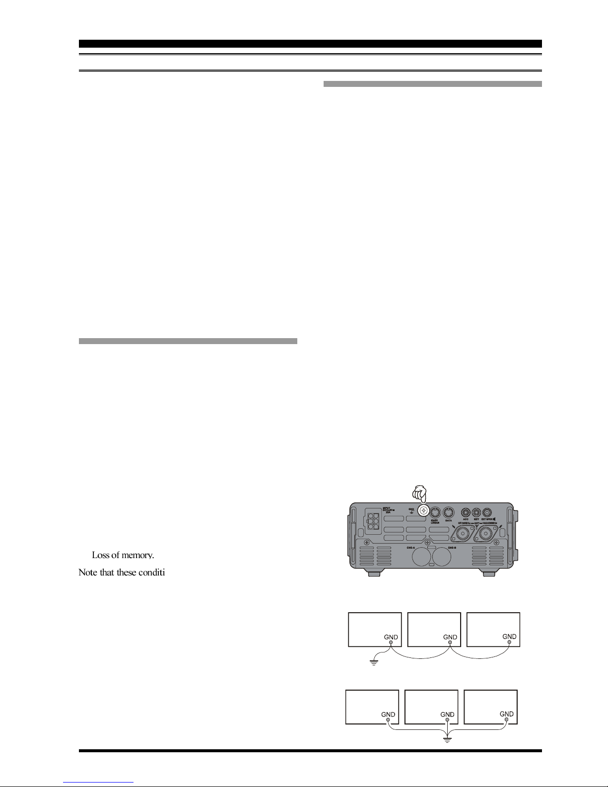
support or power-pole structural failure. Ground your an-
tennas’ support structure(s) adequately, so as to dissipate
energy absorbed during a lightning strike. Install appropri-
ate lightning arrestors in the antenna coaxial cables (and
rotator cables, if rotary antennas are used).
In the event of an approaching electrical storm, disconnect
all antenna lead-in, rotator cables, and power cables com-
pletely from your station if the storm is not immediately
in your area. Do not allow disconnected cables to touch the
case of your FT-897D transceiver or accessories, as light-
ning can easily jump from the cable to the circuitry of your
transceiver via the case, causing irreparable damage. If a
lightning storm is in progress in your immediate area, do
not attempt to disconnect the cables, as you could be killed
instantly if lightning should strike your antenna structure or
a nearby power line.
If a vertical antenna is utilized, be certain that humans and/
or pets and farm animals are kept away both from the radiat-
ing element (to prevent electrical shock and RF exposure
danger) and the ground system (in the event of an electrical
storm). The buried radials of a ground-mounted vertical
antenna can carry lethal voltages outward from the center of
the antenna in the event of a direct lightning strike.
INSTALLATION

Page 9FT-897D OPERATING MANUAL
INSTALLATION
RF FIELD EXPOSURE
This transceiver is capable of power output in excess of 50
Watts, so customers in the United States may be required to
demonstrate compliance with Federal Communications
Commission (FCC) regulations concerning maximum per-
missible exposure to radio frequency energy. Compliance is
based on the actual power output used, feedline loss, an-
tenna type and height, and other factors which can only be
evaluated as a system.
Information regarding these regulations may be available
from your Dealer, your local radio club, from the FCC di-
rectly (press releases and other information can be found on
the FCC’s site on the World Wide Web at <http://
www.fcc.gov>), or from the American Radio Relay League,
Inc. (225 Main St., Newington CT 06111 or <http://
www.arrl.org>).
Although there is negligible radio frequency (RF) leakage
from the FT-897D transceiver itself, its antenna system
should be located as far away from humans and animals as
practicable, so as to avoid the possibility of shock due to
accidental contact with the antenna or excessive long-term
exposure to RF energy. During mobile operation, do not
transmit if someone is standing adjacent to your antenna,
and use the lowest power possible.
Never stand in front of an antenna (during testing or opera-
tion) when RF power is applied, especially in the case of
430 MHz directional arrays. The 20 Watt power output sup-
plied by the FT-897D, combined with the directivity of a
beam antenna, can cause immediate heating of human or
animal tissues, and may cause other undesirable medical
effects.
ELECTROMAGNETIC COMPATIBILITY
If this transceiver is used with, or in the vicinity of, a com-
puter or computer-driven accessories, you may need to ex-
periment with grounding and/or Radio Frequency Interfer-
ence (RFI) suppression devices (such as ferrite cores) to
minimize interference to your communications caused by
energy from the computer. Computer-generated RFI is usu-
ally a result of inadequate shielding of the computer’s cabi-
net or I/O and peripheral connections. While computer equip-
ment may “comply” with RF emission standards, this does
not ensure that sensitive Amateur Radio receivers like the
FT-897D will not experience interference from the device!
Be certain to use only shielded cables for TNC-to-Trans-
ceiver connections. You may need to install AC line filters
on the power cord(s) of the suspected equipment, and
decoupling ferrite toroidal chokes may be required on inter-
connecting patch/data cables. As a last resort, you can try
installing additional shielding within the computer’s case,
using appropriate conductive mesh or conductive shielding
tape. Especially check “RF holes” where plastic is used for
cabinet front panels.
For further information, consult amateur radio reference
guides and publications relating to RFI suppression tech-
niques.
HEAT AND VENTILATION
To ensure long life of the components, be certain to provide
adequate ventilation around the cabinet of the FT-897D.
The cooling system of the transceiver must be free to draw
cool air in from the side of the transceiver and expel warm
air from the rear of the transceiver.
Do not install the transceiver on top of another heat-gener-
ating device (such as a linear amplifier), and do not place
equipment, books, or papers on top of the transceiver. Place
the transceiver on a hard, flat, stable surface. Avoid heating
vents and window locations that could expose the transceiver
to excessive direct sunlight, especially in hot climates.
Heat Dust VentilationWater & Moisture
Note
Save the packing materials in case you need to trans-
port the set (on an airplane, etc.) and/or return the set
for service.

Page 10 FT-897D OPERATING MANUAL
LINEAR AMPLIFIER INTERFACING
The FT-897D provides the switching and drive-control lines
required for easy interfacing to most all commonly-avail-
able amplifiers sold today.
These include:
ÌThe Antenna Jacks (“HF/50MHz” and “144/430MHz”);
ÌA T/R control line (open circuit on RX, closure to ground
on TX); and
ÌA negative-going ALC jack (control voltage range: 0V
to –4V DC).
ÌWhen interfacing to the VL-1000 Solid State 1 KW Lin-
ear Amplifier, the optional CT-58 Interface Cable pro-
vides for easy interconnection (requires that the Menu
Mode No-020 [CAT/LIN/TUN]setting changes to “LIN-
EAR”).
The rear-panel CAT/LINEAR jack is an 8-pin, miniature
DIN type, with the “TX GND” pin providing a closure to
ground on transmit, for T/R control of your linear amplifier.
The ACC jack is a miniature stereo type, with external ALC
input capability on the tip connection. The main shaft is the
ground return. The ring connection of the ACC jack, when
closed to ground, places the FT-897D into the transmit mode,
and sends a steady CW carrier, for amplifier (or antenna
tuner) adjustment purposes.
Typical amplifier interface circuits are shown below.
Note that some amplifiers, particularly VHF or UHF “brick”
amplifiers, offer two methods of T/R switching: application
of +13V or a closure to ground.
Be sure to configure your amplifier so that it switches via a
closure to ground, as provided by your FT-897D’s CAT/
LINEAR jack (“TX GND” pin). Alternatively, many of these
amplifiers use “RF Sensing” to control their relays; if yours
is in this category, you may then use the T/R control line
from the “TX GND” pin of the CAT/LINEAR jack for
control of your HF linear amplifier, and RF sensing for your
VHF or UHF amplifier.
The “TX GND” T/R control line is a transistor “open col-
lector” circuit, capable of handling positive amplifier relay
coil voltages of up to +50V DC and current of up to 400
mA. If you plan on using multiple linear amplifiers for dif-
ferent bands, you must provide external band-switching of
the “TX GND” relay control line from the CAT/LINEAR
jack.
Important Note!
Do not exceed the maximum voltage or current ratings
for the “TX GND” line at the CAT/LINEAR jack. This
line is not compatible with negative DC voltages, nor
AC voltages of any magnitude.
Most amplifier control relay systems require only low
DC voltage/current switching capability (typically, +12V
DC at 25 ~ 75 mA), and the switching transistor in the
FT-897D will easily accommodate such amplifiers.
INSTALLATION
ANT 1
ANT 2
REMOTE
ON
OFF
BAND DATA 1
BAND DATA 2
GND
ALC 2
ALC 1
PTT 2
PTT 1
INPUT 1
INPUT 2
CONTROL
DC48V IN
To HF Antenna
To HF Antenna
To 5 0 MH z A n t e nn a
INPUT 1
VL-1000
ANT 1
ANT 2
ANT 3
BAND-DATA 1
CAT
/LINEAR
To 144 / 430 MHz Antenna
ALC 1
CT-58 BAND DATA Cable
CT-58 ALC Cable
GND
DC 48V IN
CONTROL
*The “CT-58” consists of two separate cables: the BAND DATA cable (Part # T9101500) and the ALC Cable (T9101501).

Page 11FT-897D OPERATING MANUAL
CW KEY/KEYER CONNECTIONS
All commonly-available keyer paddles should work perfectly
with the built-in Electronic Keyer. The wiring configuration
for the paddle is shown below.
For straight-key operation, only the tip and shaft connec-
tions are used.
RECEIVER ACCESSORIES
(TAPE RECORDER ETC.)
Connection of a tape recorder or other such receiver acces-
sory is easily accomplished by using the DATA jack’s Data
Out (1200 bps) terminal (Pin 5) and Ground (Pin 2). The
audio output is fixed at 100 mV, with an impedance of 600
Ω.
INSTALLATION
Note: Even when using a straight key, you must use a three-
conductor (“stereo”) plug. If a two-conductor plug
is used, the key line will be constantly shorted to
ground.
When using an external electronic keyer, be absolutely cer-
tain that it is configured for “positive” keying, not “nega-
tive” or “grid block” keying. The “key-up” voltage of the
FT-897D is +5V, and the “key-down” current is only about
1 mA.
For CW automated keying using a personal computer, with
an external memory keyer providing for manual sending, it
usually is possible to connect the keyed lines together via a
“Y” connector. Check with the documentation accompany-
ing your keyer and your contest/DX software for any cau-
tions which need to be observed.
KEY GND
GNDKEY
COMMON
COMMON
DOT
DOT
DASH
DASH
ADJUSTING THE FRONT BAIL
The front bail of the transceiver allows the transceiver to be
tilted upward for better viewing. Simply fold bail forward
to raise the front of the transceiver, and fold bail back against
the bottom case to lower the front of the FT-897D.
DATA
DATA OUT
1200bps
GND

Page 12 FT-897D OPERATING MANUAL
Liquid Crystal Display
The Liquid Crystal Display (LCD) provides indication
of the operating frequency and other aspects of trans-
ceiver status.
FUNC Keys
These three keys select many of the most important op-
erating features of the transceiver. When you press the
[F]key, then rotate the MEM/VFO CH knob, the cur-
rent function of that key will appear above each of the
[A], [B], and [C]keys (along the bottom of the LCD).
You may scroll the display through 17 rows of functions
available for use via the [A], [B], and [C]keys.
The available features are shown in page 14.
MIC Jack
Connect the supplied MH-31A8J Hand Microphone to
this jack.
[F]Key
Press this key momentarily to enable the changing of the
function of the Multi Function keys ([A], [B], and [C])
by the MEM/VFO CH knob.
Press and hold this key for one second to activate the
“Menu” mode.
LOCK Key
Pressing this key locks the front panel keys so as to pre-
vent accidental frequency change. The LOCK key it-
self, though, will never be disabled.
MAIN DIAL
This is the main tuning dial for the transceiver. It is used
both for frequency tuning as well as “Menu” setting in
the transceiver.
AF Knob
The (inner) VOL knob adjusts the receiver audio vol-
ume level presented to the internal or external speaker.
Clockwise rotation increases the volume level.
SQL/RF Knob
In the USA version, this (outer) SQL/RF knob adjusts
the gain of the receiver’s RF and IF stages. Using Menu
Mode No-080 [SQL/RF GAIN], this control may be
changed to function as a Squelch control, which may be
used to silence background noise when no signal is
present. In the other versions, its default setting is set to
“Squelch.”
CLAR/IF SHIFT Key
Pressing this key activates the Receiver Clarifier fea-
ture. When this feature is activated, the CLAR knob is
used to set a tuning offset of up to ±9.99 kHz. The
transmitter’s frequency is not affected by the setting of
the Clarifier.
Press and hold this key for one second to activate the IF
Shift feature, which allows you to use the MEM/VFO
CH knob to adjust the center frequency of the IF filter’s
passband response.
FRONT PANEL CONTROL & SWITCHES
BATT-B
BATT-A
FAST
GND
PTT
MICMIC GN
D
+5 V
UP
DOWN
PHONES Jack
This 1/4-inch, 3-contact jack accepts either monaural or
stereo headphones with 2- or 3-contact plugs. When a
plug is inserted, the loudspeaker is disabled. The audio
level varies according to the setting of the front panel’s
AF knob.
POWER Switch
Press and hold in the POWER switch for one second to
turn to the transceiver on or off.
While the transceiver is turned on, pressing this switch
momentarily will engage the “Fast Tuning” mode, to al-
low more rapid frequency navigation (a small “running
man” icon will be observed in the bottom right-hand
corner of the LCD).

Page 13FT-897D OPERATING MANUAL
FRONT PANEL CONTROL & SWITCHES
CLAR Knob
This knob tunes the clarifier offset frequency up to ±9.99
kHz, when the Receiver Clarifier feature is activated by
pressing the CLAR/IF SHIFT key.
BAND(DWN)/BAND(UP)Key
Pressing either of these keys momentarily will cause the
frequency to be moved up or down by one frequency
band. The selections available are:
…1.8 MHz 3.5 MHz 7.0 MHz 10 MHz
14 MHz 15 MHz 18 MHz 24 MHz 28
MHz 50 MHz 88 MHz 108 MHz 144
MHz 430 MHz 1.8 MHz …
Recalling the 5 MHz band (U.S. model) requires differ-
ent procedure. See page 23 for details.
MEM/VFO CH Knob
This detented rotary switch is used for VFO frequency
tuning, memory selection, and function selection for the
[A], [B], [C]keys of the transceiver.
DSP Button
Pressing this button momentarily provides instant access
to Multi Function Row “p” (MFp), which contains the
command key for the receiver’s Digital Signal Process-
ing system. The available functions will appear as the
functions displayed above the [A], [B], and [C]keys, as
described previously.
HOME Key
Pressing this key momentarily recalls a favorite “Home”
frequency memory.
V/M Key
Pressing this key switches frequency control between the
VFO and Memory Systems.
MODE()/MODE()Key
Pressing either of these keys momentarily will change
the operating mode. The selections available are:
… USB LSB CW CWR
AM DIG PKT USB …
DSP Indicator
This indicator glows green when the DSP feature is acti-
vated.
TRANSMIT/BUSY Indicator
This indicator glows green when the squelch opens, and
turns red during transmit.
CW-T Indicator
This indicator is a visual tinning indicator for CW re-
ception, which glows green in synchronization with a
signal tuned to the center of the IF passband during CW
reception.
BATT-A, BATT-B Indicator
These LEDs indicate the battery status for the optional
FNB-78 Ni-MH battery pack while internal battery op-
eration.
The LED glows green when the battery pack is waiting
(switch to off by the A-B switch on the top panel), and
turns orange when the is the battery pack en the radio op-
erate the corresponded battery pack by the A-B switch on
the top panel. When the battery voltage is approaching the
value which indicates depletion is near, the LED blinks
orange, indicating it is time to replace the batteries.
Supply Voltage
Meter Status
: S meter
: PO meter
: Modulation Meter
: SWR Meter
: ALC Meter
Multi Function Key Status : Key Lock “ON”
/: Fast Tuning Step
Operating Frequency
: IPO Active
: ATT Active
: VOX Active
: Priority Active
: Dual Receive Active
DCS Active
Operating Mode
APO Active
: ATAS-100/-120 or FC-30 Active
: HI SWR (more the “3.0”)
: HI Temperature
: IF SHIFT Active
: Clarifier Active
Transverter Mode
CTCSS/DCS Status
: CTCSS ENC Active (Split Tone “ON”)
: CTCSS ENC Active (Split Tone “OFF”)
: CTCSS ENC/DCS DEC Active (Split Tone “ON”)
: CTCSS ENC/DEC (Tone Squelch) Active (Split Tone “ON”)
: DCS ENC Active (Split Tone “ON”)
: DCS ENC Active (Split Tone “OFF”)
: DCS ENC/DEC Active (Split Tone “ON”)
: DCS ENC/CTCSS DEC Active (Split Tone “ON”)
: CTCSS ENC/DEC (Tone Squelch) Active (Split Tone “OFF”)
: DCS ENC/DEC Active (Split Tone “OFF”)
: Odd Split
: Minus Shift
: Plus Shift
VFO A/B or
Memory CH Number
Battery Operation
LCD Details

Page 14 FT-897D OPERATING MANUAL
FRONT PANEL CONTROL & SWITCHES
Multi Function Row “b” (MFb)[MW, SKIP, TAG]
[A]Key: MW
Press and hold in the [A](MW)key for one second to transfer the contents of the VFO into a Memory register.
[B]Key: SKIP
Press the [B](SKIP)key to designate the current Memory channel to be “skipped” during scanning.
[C]Key: TAG
Press the [C](TAG)key to select the display type (Frequency or Alpha-numeric Tag) during Memory operation.
[A][
B][
C]
Multi Function Row “c” (MFc)[STO, RCL, PROC]
[A]Key: STO
Press the [A](STO)key to store the contents of the VFO into the QMB (Quick Memory Bank) register.
[B]Key: RCL
Press the [B](RCL)key to recall the QMB Memory.
[C]Key: PROC
Press the [C](PROC)key to activate the speech processor for SSB and AM transmission.
Press and hold in the [C](PROC)key for one second to recall Menu Mode No-074 [PROC LEVEL](for setting the
compression level of the AF Speech Processor).
[A][
B][
C]
Multi Function Row “d” (MFd)[RPT, REV, VOX]
[A]Key: RPT
Press the [A](RPT)key to select the direction of the uplink frequency shift (+, –, or simplex) during FM repeater
operation.
Press and hold in the [A](RPT)key for one second to recall Menu Mode No-076 [RPT SHIFT](for setting the shift
frequency offset).
[B]Key: REV
Press the [B](REV)key to reverse the transmit and receive frequencies while working through a repeater.
[C]Key: VOX
Press the [C](VOX)key enable the VOX (voice-operated transmitter switching system) in the SSB, AM, and FM modes.
Press and hold in the [C](VOX)key for one second to recall Menu Mode No-088 [VOX GAIN](for setting the VOX gain
level).
[A][
B][
C]
The [A], [B], and [C]keys select many of the most impor-
tant operating features of the transceiver. When you press
the [F]key, then rotate the MEM/VFO CH knob, the cur-
rent function of that key will appear above each of the [A],
[B], and [C]keys (along the bottom of the LCD). You may
scroll the display through 17 rows of functions available for
use via the [A], [B], and [C]keys.
BATT-B
BATT-A
FDIAL
MEM/VFO CH
Multi Function Row “a” (MFa)[A/B, A=B, SPL]
[A]Key: A/B
Press the [A](A/B) key to switch between VFO-A and VFO-B on the display.
[B]Key: A=B
Press the [B](A=B)key to copy the contents of Main VFO to be copied into the Sub VFO, so that the two VFO’s
contents will be identical.
[C]Key: SPL
Press the [C](SPL)key to activate Split frequency operation between VFO-A and VFO-B.
[A][
B][
C]
[A][
B][
C]

Page 15FT-897D OPERATING MANUAL
FRONT PANEL CONTROL & SWITCHES
Multi Function Row “e” (MFe)[TON, -------, TDCH] ([ENC, DEC, TDCH])
[A]Key: TON/ENC
Press the [A](TON)key to activate CTCSS or DCS operation on FM.
When the Split Tone feature is activated via Menu Mode No-079 [SPLIT TONE], this key function changes to “ENC” for
activation of the CTCSS Encoder or DCS Encoder. Press the [A](ENC)key to activate the encoder.
Press and hold in the [A](TON/ENC)key for one second to recall Menu Mode No-083 [TONE FREQ](for selecting the
CTCSS tone frequency).
[B]Key: ------/DEC
Normally, this key does nothing.
When the Split Tone feature is activated via Menu Mode No-079 [SPLIT TONE], this key function changes to “DEC” to
engage the DCS or CTCSS Decoder. Press the [B](DEC)key to activate the decoder.
Press and hold in the [B](DEC)key for one second to recall Menu Mode No-033 [DCS CODE](for selecting the DCS
code).
[C]Key: TDCH
Press the [C](TDCH)key to initiate CTCSS Tone or DCS Search.
[A][
B][
C]
[A][
B][
C]
Multi Function Row “h” (MFh)[SCOP, WID, STEP]
[A]Key: SCOP
Press the [A](SCOP)key to activate the Spectrum Scope Monitor feature.
Press and hold in the [A](SCOP)key for one second to initiate the Spectrum Scope.
[B]Key: WID
Press the [B](WID)key to select the visible bandwidth for the Spectrum Scope Monitor.
Press and hold in the [B](WID)key for one second to select the operating mode for the Spectrum Scope Monitor.
[C]Key: STEP
Press the [C](STEP)key to select the channel steps for Spectrum Scope Monitor.
Press and hold in the [C](STEP)key for one second to activate the MAX HOLD feature, which will display and hold the
peak signal strength level for each channel.
[A][
B][
C]
Multi Function Row “g” (MFg)[SCN, PRI, DW]
[A]Key: SCN
Press the [A](SCN)key to initiate the Scanning (in the direction of higher frequencies).
[B]Key: PRI
Press the [B](PRI)key to activate the Priority Scan feature.
[C]Key: DW
Press the [C](DW)key to activate the Dual Watch feature.
[A][
B][
C]
Multi Function Row “f” (MFf)[ARTS, SRCH, PMS]
[A]Key: ARTS
Press the [A](ARTS)key to initiate the Auto-Range Transponder mode.
Press and hold in the [A](ARTS)key for one second to recall Menu Mode No-008 [ARTS BEEP](for selecting the ARTS
“Beep” option).
[B]Key: SRCH
Press the [B](SRCH)key to activate the Smart Search feature.
Press the [B](SRCH)key to initiate Smart Search scanning.
[C]Key: PMS
Press the [C](PMS)key to activate the Programmable Memory Scan feature.
[A][
B][
C]

Page 16 FT-897D OPERATING MANUAL
FRONT PANEL CONTROL & SWITCHES
Multi Function Row “i” (MFi)[MTR, --------, DISP]
[A]Key: MTR
Pressing the [A](MTR)key repeatedly allows selection of the display function of the meter in the transmit mode.
PWR «ALC «SWR «MOD «PWR ……
The selected function will appear above the [B]key.
Press and hold in the [A](MTR)key for one second to recall Menu Mode No-062 [MTR PEAK HOLD] (for setting the
“Peak-Hold” function of the meter).
[B]Key
Pressing the [B]key repeatedly allows selection of the display function of the meter in the transmit mode.
PWR «MOD «SWR «ALC «PWR ……
[C]Key: DISP
Press the [C](DISP)key to switch the display between the Large Character and Small Character modes.
[A][
B][
C]
Multi Function Row “j” (MFj)[SPOT, BK, KYR]
[A]Key: SPOT
Press the [A](SPOT)key to activate the CW spotting heterodyne oscillator.
[B]Key: BK
Press the [B](BK)key to disable the CW “Semi” break-in operation.
Press and hold in the [B](BK)key for one second to recall Menu Mode No-029 [CW SIDE TONE](for setting the CW
side tone volume level).
[C]Key: KYR
Press the [C](KYR)key to activate the built-in Electronic Keyer.
Press and hold in the [C](KYR)key for one second to recall Menu Mode No-030 [CW SPEED](for setting the Keyer
speed).
[A][
B][
C]
[A][
B][
C]
Multi Function Row “k” (MFk)[TUNE, DOWN, UP]
[A]Key: TUNE
Press the [A](TUNE)key to activate the optional FC-30 Automatic Antenna Tuner or ATAS-100/-120 Active-Tuning
Antenna System.
Press and hold in the [A](TUNE)key for one second to initiate tuner or antenna retuning.
[B]Key: DOWN
Press and hold in the [B](DOWN)key to lower the ATAS-100/-120 antenna manually.
[C]Key: UP
Press and hold in the [C](UP)key to raise the ATAS-100/-120 antenna manually.
[A][
B][
C]
Multi Function Row “l” (MFl)[NB, AGC, --------]
[A]Key: NB
Press the [A](NB)key to activate the receiver’s IF Noise Blanker.
Press and hold in the [A](NB)key for one second to recall Menu Mode No-63 [NB LEVEL](for setting of the NB level).
[B]Key: AGC
Press the [B](AGC)key to disable the receiver’s AGC system. Normally, the AGC should be left On.
[C]Key
Press the [C]key to select the recovery time (Slow, Fast, or Auto) for the receiver’s AGC system.
[A][
B][
C]
Multi Function Row “m” (MFm)[IPO, ATT, NAR]
[A]Key: IPO
Press the [A](IPO)key to bypass the receiver preamplifier, thereby activating Intercept Point Optimization for improved
overload characteristics while operating on the HF and 50 MHz bands.
The IPO feature does not function on 144/430 MHz.
[B]Key: ATT
Press the [B](ATT)key to engage the receiver front-end attenuator, which will reduce all signals and noise by approxi-
mately 10 dB.
The ATT feature does not function on 144/430 MHz.
[C]Key: NAR
Press the [C](NAR)key to select the low-deviation mode required for HF FM operation on 29 MHz.

Page 17FT-897D OPERATING MANUAL
FRONT PANEL CONTROL & SWITCHES
Multi Function Row “o” (MFo)[PLY1, PLY2, PLY3]
[A]Key: PLY1
Press the [A](PLY1)key to send the CW message which is memorized in BEACON TEXT 1.
[B]Key: PLY2
Press the [B](PLY2)key to send the CW message which is memorized in Keyer BEACON TEXT 2.
[C]Key: PLY3
Press the [C](PLY3)key to send the CW message which is memorized in Keyer BEACON TEXT 3.
[A][
B][
C]
Multi Function Row “n” (MFn)[CFIL,--------,--------]
[A]Key: CFIL
Press the [A](CFIL)key to select the 2.4 kHz ceramic IF filter.
[B]Key
Press the [B]key to select the optional IF filter which is located on the “FIL-1” (Optional Filter 1) slot on the Main Unit.
When an optional filter is not installed on the“FIL-1” slot, this key function is disabled, and its label is “N/A.”
[C]Key
Press the [C]key to select the optional IF filter which is located on the “FIL-2” (Optional Filter 2) slot on the Main Unit.
When an optional filter is not installed on the“FIL-2” slot, this key function is disabled, and its label is “N/A.”
[A][
B][
C]
Multi Function Row “p” (MFp)[DNR, DNF, DBF]
[A]Key: DNR
Press the [A](DNR)key to activate the DSP Noise Reduction system.
Press and hold in the [A](DNR)key for one second recall Menu Mode No-049 [DSP NR LEVEL] (for setting the degree
of DSP Noise Reduction).
[B]Key: DNF
Press the [B](DNF)key to activate the DSP’s Auto Notch Filter.
[C]Key: DBF
Press the [C](DBF)key to activate the DSP’s receiver Bandpass Filter.
In the SSB, AM, FM, and AFSK modes, press and hold in the [C](DBF)key for one second to recall Menu Mode No-
047 [DSP LPF CUTOFF] (for adjusting the high-frequency cutoff of the DSP Bandpass Filter).
In the CW mode, press and hold in the [C](DBF)key for one second to recall Menu Item No-045 [DSP BPF WIDTH]
(for setting the CW bandwidth).
[A][
B][
C]
Multi Function Row “q” (MFq)[MONI, QSPL, ATC]
[A]Key: MONI
Press the [A](MONI)key to disable the Noise Squelch.
You may program the configuration of this key by the Menu Mode No-065 [PG A].
[B]Key: QSPL
Press the [B](QSPL)key to change the Sub VFO frequency (Main VFO frequency + 5 kHz) and automatically engage
the “Split” feature.
You may program the configuration of this key by the Menu Mode No-066 [PG B].
[C]Key: ATC
Press the [C](ATC)key to activate a 1750-Hz burst tone for 2 seconds when pressing the PTT switch while the channel
is clear.
You may program the configuration of this key by the Menu Mode No-067 [PG C].

Page 18 FT-897D OPERATING MANUAL
INPUT Jack
This is the DC power supply connection for the trans-
ceiver, used when operating the transceiver with an ex-
ternal power supply. Use the supplied DC cable to con-
nect this jack to the car battery or DC power supply,
which must be capable of supplying at least 22A @ 13.8
VDC. For base station operation, the optional FP-30
External AC power supply may be attached to the bot-
tom of the transceiver and connect the output pigtail of
the FP-30 to this jack.
GND Terminal
For best performance and safety, this Ground lug may
be connected to a good earth ground using a short, heavy,
braided cable.
CAT/LINEAR Jack
This 8-pin mini-DIN jack is used for connection to the
FC-30 External Automatic Antenna Tuner or ATAS-100/
-120 Active-Tuning Antenna System. It is also used for
interfacing to a personal computer for control of the trans-
ceiver using the CAT system, and for interconnection
to the VL-1000 Linear Amplifier.
ACC Jack
This 3.5-mm 3-pin jack accepts external ALC (Automatic
Level Control) voltage from a linear amplifier on the tip
connection, and accepts a “Transmit Request” command
on the ring connection. The main shaft is the ground re-
turn.
The “TX Request” connection, when shorted to ground,
puts the FT-897D into the transmit mode, and sends out
a steady CW carrier, for linear amplifier or manual an-
tenna tuner adjustment.
REAR PANEL CONNECTORS
KEY Jack
This 3.5-mm, 3-pin jack is used for connection to a CW
keyer paddle or a straight key.
EXT SPKR Jack
This 3.5-mm, 2-pin jack provides variable audio output
for an external speaker. The audio output impedance at
this jack is 4 Ω~ 16 Ωand the level varies according to
the setting of the front panel’s AF control.
CAT
/TUNER
+13.8V
BAND C
RESE
T
TX INH
RX D
TX D
TX GND
GND
LINEAR
+13.8V
BAND C
BAND D
TX INH
BAND B
BAND A
TX GND
GND
DATA Jack
This 6-pin, mini-DIN jack accepts AFSK input from a
Terminal Node Controller (TNC); it also provides fixed-
level Receiver Audio Output, Push-To-Talk (PTT),
Squelch Status, and ground lines.
DATA
DATA OUT
1200bps
DATA OUT
9600bps
SQL
GND
PTT
DATA IN
144/430 MHz Antenna Jack
Connect your 144 and/or 430 MHz antenna’s 50 Ωco-
axial cable to this M-type (“SO-239”) connector.
HF/50 MHz Antenna Jack
Connect your HF and/or 50 MHz antenna’s 50 Ωco-
axial cable to this M-type (“SO-239”) connector.
SIGNAL GND
EXT ALC GND
TX REQ
Other manuals for FT-897D
1
This manual suits for next models
1
Table of contents
Other Yaesu Transceiver manuals

Yaesu
Yaesu FT-7900R Manual

Yaesu
Yaesu FTM-400XD User manual

Yaesu
Yaesu FT-690R User manual

Yaesu
Yaesu FT-2000 - MENU MODE LIST User manual

Yaesu
Yaesu FT-415 Manual

Yaesu
Yaesu FT-950 Technical manual

Yaesu
Yaesu FT-902DM User manual

Yaesu
Yaesu FTH-2006 Owner's manual

Yaesu
Yaesu FT-747GX User manual

Yaesu
Yaesu FT-70DR User manual

Yaesu
Yaesu FTDX-9000D General instructions

Yaesu
Yaesu FT-25E User manual

Yaesu
Yaesu FT-900 User manual

Yaesu
Yaesu FTA-250L User manual

Yaesu
Yaesu FT-757GX II User manual

Yaesu
Yaesu VX-3R Manual

Yaesu
Yaesu Mark-V FT-1000MP Manual

Yaesu
Yaesu FTV-107R User manual

Yaesu
Yaesu FT-2200 User manual

Yaesu
Yaesu FT3DE User manual