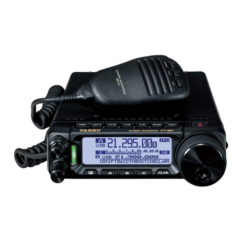
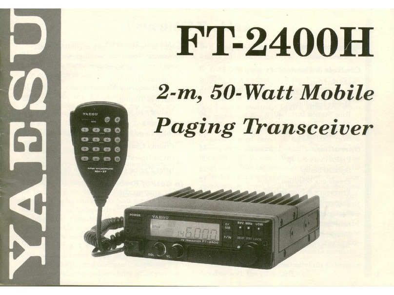
Yaesu FT-902DM User manual

INSTRUCTION
MANUAL
FT-902DM
YAESU
MUSEN
CO.,
LTD.
TOKYO
JAPAN

ALL
MODE
HF
TRANSCEIVER
FT-902DM
el
—_—
~~
SSS
SSS
Ss
[SESS
:
SSA
=
4a
GENERAL
DESCRIPTION
The
FY-902DM
is
a
precision
engineered,
high
per-
formance
HF
transceiver
of
advanced
design,
pro-
viding
all
band
coverage
(160,
80.40,
30.
20,
17,
15,
|2,and
|]Ometers)
on
all
modes
of
operation:
LSB,
USB,
CW,
FSK,
AM,
and
FM.
This
trans-
ceiver
operates
alan
input
power
of
180
watts
on
SSB/CW
and
80
watts
on
AM,
FM,
and
FSK.
Advanced
features
include
PLL
(Phase
Locked
Loop)
frequency
derivation,
digital
plus.
analog
frequency
readout
with
large
displuy
LED
digits,
a
built-in
Curtis
8044
IC
electronic
keyer,
and
memory
frequency
control
circuilry.
Staite-of-the-
art
receiver
performance
features
Include
rejection
tuning,
dualfilter
variable
IF
bandwidth
tuning,
and,
for
CW,
audio
peak
frequency
(APF)
tuning
for
unsurpassed
rejection
of
unwanted
signals.
Other
built-in
features
include
VOX,
semi-break-
in
CW
with
sidetone,
25
kHz
calibrator,
advanced
noise
blanker,
RF
speech
processor.
and
a
20
dB
RE
attenuator
for
protection
against
receiver
overload,
All
circuits,
except
the
transmilter
driver
and
final
amplifier
stages,
are
solid
state,
utilizing
modern
plug-in
printed
circuit
boards,
thus
per-
mitting
easy
maintenance.
The
FT-902DM
transceiver
is
entirely
self-con-
lained,
requiring
only
an
antenna
and
power
source
for
operation.
For
base
station
operation,
AC
power
voltages
of
LOO/110/117/200/220/234
VAC
may
be
chosen,
though
the
unit
normally
is
sup-
plied
with
117
volt
capability.
A
DC-DC
converter
unil
provides
fer
mobile
or
portable
operation.
Selection
of
AC
or
DC
power
source
is
automati-
cally
made
when
the
proper
line
cord
is
inserted.
For
mobile
operation
a
separate
switch
is
provided
on
the
front
panel
to
turn
olf
the
tube
heaters
while
in
the
receive
mode.
With
the
heaters
off,
current
consumption
is
only
1.1
amp.
Among
the
available
options
on
economy
models
FT-902D/SD/DE
are
the
memory
unit,
the
keyer
unit,
the
DC-DC
converter,
the
FM
unil,
and
the
cooling
fan.
Optional
equipment
on
all
modets
are
the
600
[lz
CW
filter
and
the
6
KHz
AM
filter.
The
entire
PT-902DM
transceiver
weighs
approxi-
mately
18
kg.,
and
is
342
mm
wide,
154
mm
high,
and
324
mm
deep.
A
diecast
front
panel
and
heavy-duty
case
provide
maximum
protection
against
damage
from
shock
and
vibration
during
travel
use.

SPECIFICATIONS
©
GENERAL
Frequency
coverage:
160m
1.8
-
2.0
MHz
80m
3.5
-
4.0
MHz
40m
7.0-
7.5
MHz
30m
10.0
-
10.5
MHz
20m
14.0
-
14.5
MHz
17m
18.0
-
18.5
MHz
15m
21.0
-
21.5
MHz
12m
24.5
-
25.0
MHz
10mA
28.5
-
28.5
MHz
10mB
28.5
-
29.0
MHz
10mC
29.0
-
29.5
MHz
10mD
29.5
-
29.9
MHz
Power
requirements:
AC
100/110/117/200/220/234
V,
50/60
Hz
DC
13.5
V,
negative
ground
(DC
option
FT-902D/SD/DE)
Power
consumption:
(FT-902DM/D/DE)
AC
117
V:
70
watts
receive
(45
watts
HEATER
OFF)
320
watts
transmit
(max)
DC
13.5
V:
5A
receive
(1.1
A
HEATER
OFF)
21
A
transmit
(max)
(FT-902SD)
AC
117V:
55
watts-receive
(45
watts
HEATER
OFF)
105
watts
transmit
(max)
DC
13.5
V:
3.8
A
receive
(0.8
A
HEATER
OFF)
7.5
A
transmit
(max)
Size:
342
(W)
x
154
(H)
x
324
(D)
mm
Weight:
I8kg
TRANSMITTER
Emission:
LSB,
USB
(A3j),
CW
(Al),
AM
(A3h),
FM
(F3)
(option
FT-902SD/DE),
FSK
(F1)
PA
input
power:
FT-902DM/D/DE
SSB/CW:
180
watts
DC
AM/FSK/FM:
80
watts
DC
FT-902SD
SSB/CW/FSK/FM:
20
watts
DC
AM:
5
watts
DC
:
Carrier
suppression:
Better
than
40
dB
Unwanted
sideband
suppression:
Better
than
40
dB
@
1000
Hz
Spurious
radiation:
Better
than
40
dB
below
rated
output
Transmitter
frequency
response:
300
-
2700
Hz
(6
dB)
Third
order
distortion
products:
Better
than
31
dB
below
rated
output
Transmitter
frequency
stability:
Less
than
300
Hz
after
10
minute
warmup:
less
than
100
Hz
after
30
minute
warmup.
Negative
feedback:
6
dB
at
14
MHz
Modulation:
A3J:
Balanced
modulator
A3h:
Amplitude
modulation
of
a
low
power
stage
F3:
Variable-reactance
frequency
modula-
tion,
max.
deviation
+5
kHz
(F3
fea-
ture
optional
on
FT-902SD/DE)
Antenna
output
impedance:
50-75
Ohms,
unbalanced
Microphone
input
impedance:
500
-
600
Ohms

RECEIVER
Passband
tuning:
Continuous
from
2.4
kHz
to
300
Hz
Sensitivity:
SSB/CW/FSK
0.25
pV
for
S/N
10
dB
Intermodulation:
AM
1
uv
for
S/N
10
dB
Better
than
80
dB
immunity
at
20
kHz
offset
FM
0.3
uV
for
20
dB
quieting
20
dB
inputs
at
14
MHz
Image
rejection:
Desensitization:
1.8-
25
MHz
-
-
Better
than
60
dB
Better
than
100
dB
immunity
at
20
kHz
off
28
MHz
-
-
Better
than
50
dB
20
dB
input
at
14
MHz
IF
rejection:
APF
response:
Better
than
70
dB
Within
3
dB
from
400
-
900
Hz
Selectivity,
WIDTH
control
at
“0”
Audio
output:
SSB:
-6
dB/2.4kHz
—60
dB/4.0
kHz
Better
than
3
watts
@
10%
THD
*CW:
-—6dB/0.6kHz
—60dB/1.2
kHz
*AM:
—6dB/6.0kHz
-—60
dB/12.0
kHz
Audio
output
impedance:
**FM:
—6
dB/12.0
kHz
—60
dB/24.0
kHz
ALAS
Ohms
*AM
and
CW
filters
are
optional,
all
models
**FM
UNIT
optional
on
FT-902SD/DE
FT-902D/SD/DE/DM
MODEL
DIFFERENCES
O
=
Built-in
feature
X
=
Available
option
FEATURE
"
FT-9020
|
FT-902SD
|
FT-902DE
'
FT-902DM
—
BANDCRYSTAL
160m
OO
O
See
ae
Oe.
BAND
CRYSTAL
80m
ss
O
om
cm
oO
|
BAND
CRYSTAL
40m
|
fe)
O
eo
if
oO
BAND
CRYSTAL
30m
|
eee
OT
ee
2
“BAND
CRYSTAL
20m
G2.
oO
|
O
Oo.
BAND
CRYSTAL
17m
Oo
|
om
30
ic)
-BANDCRYSTAL
15m
=|
O..—
O
Ge.
|
Onc!
BAND
CRYSTAL
12m
|
Or.
fon
it
ee
Oo.
|
BAND
CRYSTAL
—-10mA__
O
O
oO
oan
BAND
CRYSTAL
10mB
leg
Orch
—
JO
o.
-|.
=-6
_BAND
CRYSTAL
__10mC
“Or,
=
lit
OL
I
Or).
-
Oe
BAND
CRYSTAL
—_10mD
io
“©
O
0
-VOX/MARKER
UNIT
0
O
on
O-
FM
UNIT
as
em
al
oa
a
ae
%
O.
|
_RF
SPEECH
PROCESSOR
_
oO
O
sue),
i
Os
AM
FILTER
7
x
x x
XP
CW
FILTER
|
—,
x
Ne
x
4
FM
FILTER
=
x
.
a
a
x
_KEYER
UNIT
;
|
x
-.
or
eas)
MEMORY
UNIT
;
|
x
x
=
oe
ee
Cs
_DC-DC
CONVERTER
-
|
x
x
x
O
COOLING
FAN
o
|...
&
ec
or
|i
_POWER
OUTPUT
=
=
=—S
|s~Ss«100
W
10W-
100
W
100
W

TUBE
COMPLEMENT
12BY7A
1
6146B
2
SEMICONDUCTOR
COMPLEMENT
Germanium
Transistor:
T20A6
2
Silicon
Transistor
:
2SA496Y
2
2SA564A-R
2
2SA639
1
28A733
3
2SA952L
13
28C372Y
4
2SC380TM-Y
15
2SC535A
1
2SC732TM
5
2SC735Y
3
2SC785-O
3
2SC1674L
1
2SC1815Y
29
2SC1815GR
11
2S8C2407
2
MPSA13
1
FET:
2SK19GR
11
2SK19TM-BL
10
2SK34E
1
3SK40M
3
3SK51-03
9
3SK59Y
1
3SK59GR
1
3SK73
1
JF1033B
4
J310
1
Ic:
MC3403P
MC14011BCP
MC14042BCP
MC4044P
(uPC1008C)
TA7205AP
1
TA7063P
2
TA7061AP
2
TA7310P
|
TA7089M
1
TA7060P
1
I
2
3
1
1
]
NON
TC503
2P
uPC14305
uPC14308
uPC14312
uPAS4H
SN75450B
Specifications
subject
to
change
without
notice.
SN74LS192N
SN74LSO0ON
SN74LS04N
SN74LS123N
MSM5562
MSM9520RS
MM74C90N
NJM78LOS5A
NJM78L08
LM308
8044
34024PCQM
Germanium
Diode:
1N60
1S188FM
181007
Silicon
Diode:
181555
1SS53
10D1
10D10
VO6B
SM1-12
—
i
OND
Ss
RE
OND
SO
12
6
30
101
ee
WN
wo
ON
Varactor
Diode:
182209
2
182236
]
FC63
]
MV104
12
Zener
Diode:
WZ050
2
WZ060
1
WZ090
5
WZ110
2
Schottky
Barrier
Diode:
ND487C2
1
LED:
GD4-203SRD
12
LED
Display:
HP5082-7623
6

CONTROLS
AND
SWITCHES
This
transceiver
has
been
specifically
designed
for
ease
of
operation
and
versatility.
The
operator
may,
however.
be
unfamiliar
with
the
operation
of
the
controls,
and
improper
adjustment
thereof
may
result
in
poor
transceiver
performance.
Thus,
be
certain
that
you
understand
the
function
of
every
control
before
operating
the
transceiver,
The
various
front
panel
controls
and
switches
are
described
in
the
following
section,
/
(1)
MODE
The
MODE
switch
has
six
positions
for
selection
of
the
operating
mode
desired!
LSB,
USB,
CW.
FSK,
AM,
or
FM.
(2)
REJECT-WIDTH
The
REJECT
und
WIDTH
controls
are
mounted
on
concentric
shafts:
The
rejection
tuning
control
(REJECT).
when
activated
by
pressing
the
small
the
left
of
the
REJECT
knob,
provides
u
variable
IF
notch
filter
action
for
nulling
Oul
a
particular
interfering
signal,
silver
pushbutton.
to
The
WIDTH
control
varies
the
signal
across
the
passband
of
one
of
the
two
IF
8-pole
crystal
band-
pass
filters
used
in
this
circuit.
thus
providing
a
variable
IF
bandwidth
for
rejection
of
signals
above
or
below
the
desired
signal,
(3)
M
The
M
button
is
pressed
to
store
a
frequency
in
the
memory
circuitry.
Whatever
lrequency
is
being
read
out
on
the
digital
display
will
be
the
lrequency
stored
when
the
M
button
is
pushed.
mA
*
Tololeloioroy
mes
AH)
SEES
FOG
(4)
EXT
When
pushed,
the
EXT
button
transfers
frequency
control
from
the
FT-902DM
to
an
external
VFO,
such
as
the
FV-901DM
fully
synthesized
scanning
VFO.
(5)
VEO
When
the
VFO
button
is
pushed,
frequeney
con-
trol
is
transfered
from
EXT
or
memory
control
to
the
FT-902DM
internal
VFO,
(6)
TX-MR-RX
Once
a
frequency
has
been
stored
by
the
memory
(M)
button,
that
frequency
may
be
recalled
for
control
of
either
the
transmit
or
reeeive
frequency
by
pushing
either
the
TX
or
RX
MR
_
button,
respectively,
(7)
MR
Once
a
frequency
has
been
stored
by
the
memory
(M)
button,
that
frequency
may
be
recalled
for
control
of
the
transceive
frequency
by
pushing
the
MR
button.

(8)
PRESELECT
This
control
pretunes
the
signal
circuits
for
both
transmit
and
receive.
The
PRESELECT
circuit
provides
continuous
permeability
tuning
through-
out
the
frequency
range
of
the
transceiver.
(9)
BAND
The
BAND
switch
provides
selection
of
the
band
desired,
160
through
10
meters.
(10)
RF
GAIN/CLARIFIER
The
RE
GAIN
and
CLARIFIER
controls
are
mounted
on
concentric
shafts.
The
RF
GAIN
control
provides
manual
control
of
the
gain
levels
of
the
RF
and
IF
amplifiers
on
receive.
The
CLARIFIER
control
allows
manual
offset
of
42.5
kHz
of
either
the
transmit
or
receive
fre-
quency.
Selection
of
transmit
or
receive
clarifier
is
made
hy
the
two
silver
pushbuttons
to
the
left
of
the
CLARIFIER
control.
(11)
ATT
The
ATT
(RF
attenuator)
button
provides
inser-
tion
of
a
20
dB
attenuator
in
the
incoming
signal
path
to
minimize
receiver
cross
modulation
caused
by
extremely
strong
local
signals.
(12)
PROC
LEVEL/AF
GAIN
The
PROC
LEVEL
and
AF
GAIN
controls
are
mounted
on
concentric
shafts.
The
PROC
LEVEL
control
allows
manual
control
of
the
output
level
of
the
RF
speech
processor.
The
processor
is
actuated
by
pressing
the
silver
pushbutton
to
the
left
of
the
PROC
LEVEL
control.
The
AF
GAIN
control
adjusts
the
audio
output
level
at
the
speaker
and
phone
jack.
Clockwise
rotation
increases
the
audio
output.
(13)
TUNE
This
pushbutton,
when
depressed,
places
the
trans-
mitter
in
the
“tune”
condition
for
ten
seconds
for
tuning
purposes.
After
ten
seconds,
the
trans-
ceiver
is
returned
to
the
receive
mode
so
as
to
prevent
damage
to
the
final
amplifier
tubes
caused
by
excessive
“key
down”
time
during
tune-up.
(14)
LOADING
This
control
tunes
the
output
circuit
of
the
pi
net-
work
to
match
the
antenna/feedline
impedance.
(15)
PLATE
This
control
tunes
the
plate
circuit
of
the
final
amplifier.
(16)
DIM
This
control
allows
dimming
of
the
meter
and
dial
lamps.
(17)
CARR/KEYER
The
CARR
and
KEYER
controls
are
mounted
on
concentric
shafts.
The
CARR
control
varies
the
amount
of
carrier
in
the
CW,
AM,
FSK,
and
FM
models
of
operation.
The
KEYER
control
varies
the
speed
of
the
built-in
Curtis
8044
IC
electronic
keyer.
(18)
VOX
GAIN
This
control
selects
MOX/PTT/VOX
transmitter
relay
control
as
well
as
adjusting
the
sensitivity
of
the
VOX
circuitry.
The
PTT
position
provides
push-to-talk
operation
from
a
microphone
PTT
switch
or
a
footswitch.
The
MOX
position
provides
manual
transmit.
It
must
be
returned
to
the
PTT
position
for
receiver
recovery.
(19)
APF
FREQ
This
knob,
when
actuated
by
turning
on
the
APF
switch,
provides
manual
control
for
peaking
the
audio
peak
filter
(APF)
circuit
on
the
desired
signal.
This
control
will
find
its
chief
usefulness
on
CW,
because
its
bandwidth
is
much
too
narrow
for
normal
SSB
reception.
(20)
SQL/MIC
GAIN
The
SQL
and
MIC
GAIN
controls
are
mounted
on
concentric
shafts.
The
SQL
control
sets
the
squelch
threshold
level
for
FM
reception.
The
MIC
GAIN
control
varies
the
audio
level
from
the
microphone
amplifier
stage.
The
control
has
sufficient
range
to
permit
the
use
of
any
low
im-
pedance
(500
-
600
Ohm)
crystal
or
dynamic
microphone.
Clockwise
rotation
increases
the
level
of
output
from
the
microphone
amplifier
stage.
(21)
FUNCTION
SWITCHES:
AMGC,
APF/MONI,
AGC,
PO/IC/ALC,
and
NB/MARK
The
AMGC
switch
activates
a
microphone
gain
threshold
circuit
which
requires
a_
particular

minimum
input
level
from
the
microphone
to
trigger
the
microphone
amplifier.
Low-level
back-
ground
noise
will
not
activate
the
transmitter
with
the
AMGC
in
operation.
This
circuit
may
be
considered
a
‘“‘microphone
squelch”
system.
The
M
GAIN
control
functions
normally
with
the
AMGC
system
in
operation.
When
the
APF/MONI
switch
is
in
the
APF
posi-
tion,
the
audio
peak
filter
(APF)
circuitry
is
activated.
The
exact
frequency
of
the
audio
peak
is
set
by
the
APF
FREQ
knob.
When
this
switch
is
placed
in
the
MONI
position,
monitor-
ing
of
the
microphone
level
may
be
accomplished
for
operator
convenience
or
tape
recording
both
sides
of
a
QSO.
In
the
CW
mode,
CW
sidetone
will
be
heard
regardless
of
the
position
of
the
APF/MONI
switch.
The
AGC
switch
controls
the
length
of
the
re-
covery
time
for
the
receiver
AGC
circuitry.
This
switch
provides
slow
or
fast
recovery,
and
will
also
turn
off
the
AGC
if
desired.
The
PO/IC/ALC
switch
will
hereafter
be
referred
to
as
the
METER
switch.
In
the
PO
position,
relative
transmitter
output
power
can
be
observed.
In
the
IC
position,
transmitter
final
amplifier
cathode
current
may
be
measured.
In
the
ALC
position,
transmitter
ALC
voltage
may
be
read.
When
the
FT-902DM
is
in
the
receive
mode,
the
meter
functions
as
an
“‘S”’
meter.
The
NB/MARK
switch
provides
for
actuation
of
either
the
Noise
Blanker
(NB)
or
crystal
calibrator
(MARK).
The
marker
oscillator
can
produce
cali-
bration
signals
at
intervals
of
either
25
kHz
or
100
kHz
by
proper
positioning
of
a
switch
inside
the
cabinet.
(22)
POWER
This
is
the
main
on/off
switch
for
the
transceiver.
In
the
OFF
position,
the
memory
circuits
are
disabled,
so
that
when
the
transceiver
is
turned
to
ON
again,
the
memory
circuits
will
have
to
be
reset.
(23)
HEATER
With
the
HEATER
switch
in
the
down
position,
the
transmitter
tube
heaters
are
turned
off.
This
reduces
battery
drain
to
1.1
amp
and
thus
permits
long
periods
of
listening
without
excessive
battery
drain.
Placing
this
switch
in
the
up
position
pro-
vides
supply
voltage
to
the
tube
heaters,
and
after
30
seconds
of
warmup
the
transmitter
is
ready
for
operation.
This
switch
operates
in
both
the
AC
and
DC
modes.
(24)
PHONES
This
is
a
standard
1/4”
phone
jack
for
accom-
modation
of
headphones.
The
internal
speaker
is
disabled
when
headphones
are
plugged
into
this
jack.
(25)
MIC
This
four-conductor
jack
accommodates
the
microphone
plug
for
microphone
input
as
well
as
for
PTT
actuation.
MIC
Mic
plug
Headphone
plug

REAR
APRON
CONNECTIONS
(1)
GND
Threaded
lug
for
ground
connection.
(2)
RF
OUT
Signal
frequency
output
from
the
driver
stage
may
be
obtained
at
this
jack
for
use
with
optional
equipment,
such
as
the
FTY-90O1R
transverter.
(3)
ANT
Coaxial
conneclion
for
antenna.
(4)
PO
ADJ
Sets
PO
meter
sensitivity.
(S)
RCV
ANT
A
second
receiver
receives
its
antenna
connection
through
this
jack,
(6)
ACC
Accessory
socket.
Provides
access
to
transceiver
operating
voltages
and
relay
contacts.
(7)
KEY
Three-conductor
jack
for
connection
to
keyer
paddle
or
external
key,
(8)
EXT
VFO
Connections
for
external
VFO.
ral
(9)
FUSE
Fuse
holder
requires
5
amp
fuse
for
117
volt
or
3
amp
fuse
for
220
volt
operation,
For
12
volt
DC
operation,
a
20
amp
fuse
ts
installed
in
the
power
cable,
When
replacing
fuses,
be
certain
to
install
a
fuse
of
the
proper
rating.
The
caused
by
improper
fuse
warranty
does
not
cover
damage
replacement.
(10)
POWER
Power
receptacie.
Both
AC
and
DC
cables
are
supplied.
(11)
TONE
Sidetone
output
for
second
receiver
(if
used).
(12)
IF
OUT
2
Wide-bandwidth
8.9
MHz
IP
signal
for
connection
to
a
spectrum
analyzer,
ete,
(13)
PATCH
Speech
input
terminal
for
phone
patch
connection.
Impedance
is
500
ohms,
(14)
A-TRIP
Anti-trip
input
from
second
receiver
(if
used).
(15)
SP
Audio
output
is
provided
at
this
jack
for
an
ex-
ternal
speaker.
Outpul
impedance
ts
4
ohms,
and

the
internal
speaker
will
be
disabled
when
plug
is
inserted.
(16)
PTT
This
jack
may
be
used
for
external
actuation
of
the
transmitter.
As
an
example,
a
footswitch
may
be
connected
to
this
jack
to
provide
remote
con-
PIN
No.
;
;
1
HEATER
trol
of
the
transmitter
relay,
leaving
the
operator’s
2
HEATER
hands
free
for
writing
and
tuning
purposes.
4
+300V
5
+800V
6
—100V
7
ALC
(17)
FSK
9
TX
GND
.
10
RX
GND
Input
from
the
FSK
terminal
may
be
made
WNC
through
this
jack.
The
FT-902DM
is
set
up
for
1
170
Hz
shift.
eens
(18)
IF
OUT
1
Narrow
bandwidth
8.9
MHz
IF
output
is
avail-
KN
able
for
use
with
an
IF
monitorscope,
etc.
PExTIN
3
EXT
OV
(19)
REMOTE
4
AGC
OUT
5
TX12V
6
GND
Provides
switched
13.5
VDC
for
relay
control
for
external
low-pass
filter
units,
etc.
As
the
band-
EXT
VFO
PLUG
switch
is
rotated,
13.5
VDC
will
appear
at
various
pins
on
the
REMOTE
jack.
Use
a
VOM
to
deter-
mine
the
proper
pin
for
the
band
in
use.
—
i
HU
et
S>
oot
neeney
MMON
©
q
AO
he
Ss
‘3
i+
Se
)
Ma
ML
Pin
plug
Cooling
fan
|
External
speaker
,
\

INTERCONNECTIONS
TELEPHONE
LINE
FL-2100Z
FT-902DM
LINE
SP-901P
REOUT
RE
IN”
GNO
~
ALG
RY
-
?
!
@
1)
Pp
wT
|
Bag
.
ak
oa
titowzw
OU
;
-
PIN
je)
|
FV-101Z/
FV-901DM
PIN
1
PING
-
GND
ACC
PIN
9
(INNER
CONOUCTOR)
*
PIN
8
(OUTER
CONDUCTOR)
ace
PIN
7
(INNER
CONDUCTOR)
exe)
“PIN
8
(OUTER
CONDUCTOR)
O
Gp
¢
:
~
aed
@)
U
EXTERNAL
RECEIVER
HF
ANTENNA
OPOOO
MUTE
PLUG
FTV-
Sono
EXT
;)
FT-9020M
430MHz
ANTENNA
5
wenwrewns
(Coll
WM:
fe)
OUTPUT
144MHz
ANTENNA
|
r
.
ll
ag
0
50MHz
ANTENNA
|
-_
i=}
CABLE
C
CABLE
A

INSTALLATION
This
transceiver
is
designed
to
be
a
single-unit
station
for
fixed,
portable,
or
mobile
operation.
Consequently,
power
supply
connections
provid-
ing
for
operation
from
a
variety
of
source
voltages
are
available.
This
system
provides
the
flexiblity
required
for
changing
locations
or
quick
moves
from
fixed
to
mobile
operation.
BASE
STATION
INSTALLATION
The
FT-902DM
is
designed
for
use
in
many
areas
of
the
world
using
supply
voltages
that
may
differ
from
the
operator’s
local
supply
voltage.
For
this
reason,
be
sure
that
the
voltage
marked
on
the
rear
of
the
transceiver
agrees
with
the
local
AC
supply
voltage.
THIS
INSPECTION
MUST
BE
MADE
BEFORE
CONNECTING
THE
AC
POW-
ER
CORD
TO
THE
POWER
OUTLET.
CAUTION
PERMANENT
DAMAGE
WILL
RESULT
IF
IM-
PROPER
AC
SUPPLY
VOLTAGE
IS
APPLIED
TO
THE
TRANSCEIVER.
The
transceiver
should
be
connected
to
a
good
earth
ground.
The
ground
lead
should
be
made
with
a
heavy
braid
wire
and
should
be
connected
to
the
GND
terminal
on
the
rear
apron
of
the
transceiver.
We
do
not
recommend
the
use
of
power
con-
nectors
other
than
the
ones
supplied
by
Yaesu.
If
a
rig
brought
in
for
servicing
is
blowing
fuses
every
time
you
plug
it
in,
check
to
make
sure
that
no
“improvements”
have
been
made
to
the
power
cord
through
substitution
of
or
modification
to
the
power
connector.
For
base
station
installation,
the
only
important
consideration
that
need
be
made
is
to
ensure
adequate
circulation
around
the
unit.
Do
not
place
books
or
papers
on
or
around
the
cabinet,
nor
should
the
unit
be
placed
on
top
of
another
heat-generating
device
such
as
a
linear
amplifier.
Avoid
heat
ducts
and
window
locations
which
are
exposed
to
the
hot
sun,
and
you
will
keep
your
transceiver
running
at
full
speed
for
a
long,
long
time.
Be
certain
to
ground
the
transceiver
through
a
heavy,
braided
cable
less
than
10
feet
long.
Cold
water
pipes
in
newer
houses
probably
are
unsatis-
factory
as
grounding
posts;
it
is
much
better
practice
to
use
a
system
of
one
or
more
ground
rods,
with
the
ground
line
securely
bonded
to
the
ground
system.
MOBILE
INSTALLATION
(Note:
The
DC-DC
converter
described
herein
is
built-in
on
the
FT-902DM,
and
is
an
available
option
on
the
FT-902D/SD/DE
models)
The
FT-902DM
will
operate
satisfactorily
from
any
13.5
Volt
DC
negative-ground
battery
source
by
connecting
the
DC
power
cord
to
the
rear
panel
receptacle.
For
under-dash
mounting,
a
special
mobile
mounting
bracket
is
available
from
your
dealer.
In
mobile
installations
the
trans-
ceiver
should
be
suited
away
from
heater
ducts.
No
special
precautions
need
be
observed
if
ade-
quate
ventilation
spaces
is
available.
A
minimum
of
two
inches
of
air
space
above
the
cabinet
top
and
on
all
sides
is
recommended
to
allow
proper
air
flow
around
the
cabinet.
Never
stack
other
units
above
or
below
the
transceiver
since
the
accumulated
heat
from
both
units
could
cause
damage.
The
transceiver
requires
an
average
of
14
amps
on
transmit,
with
20
amps
on
voice
peaks.
The
DC
power
cable
comes
equipped
with
a
20
amp
fuse.
When
making
connections
to
the
car
battery,
be
absolutely
certain
that
the
RED
lead
is
con-
nected
to
the
positive
(+)
terminal
and
the
BLACK
lead
is
connected
to
the
negative
(—)
terminal.
Reversed
connections
could
permanently
damage
the
transceiver.
FUSE
HOLDER
FUSE
HOLOER
FUSE
HOLOER
—-]]--

The
BLACK
lead
should,
preferably,
run
directly
to
the
negative
terminal
of
the
battery.
Using
the
car
frame
as
a
negative
connection
or
connecting
the
RED
lead
to
a
positive
point
such
as
the
ig-
nition
switch
places
the
transceiver
in
the
same
current
path
as
noise-creating
devices,
thus
failing
to
take
advantage
of
the
filtering
action
of
the
battery.
The
power
cable
should
be
kept
away
from
ignition
wires
and
should
be
as
short
as
possible
to
minimize
voltage
drop
and
to
provide
a
low
impedance
path
from
the
transceiver
to
the
battery.
Before
connecting
the
power
cable
to
the
trans-
ceiver,
check
the
battery
voltage
with
the
engine
running
(battery
charging).
If
the
voltage
exceeds
15
Volts
DC,
the
regulator
should
be
readjusted
so
that
the
highest
charging
rate
does
not
ex-
ceed
15
Volts.
The
transceiver
should
always
be
switched
OFF
while
the
car
engine
is
being
started
to
prevent
voltage
transients
from
damaging
power
supply
components.
J]
Width
="
Width
=
'"'-1"'
Width
Control
Action
Rejection
Tuning
Action
ANTENNA
CONSIDERATIONS
The
FT-902
transceivers
are
designed
for
operation
using
an
antenna
system
presenting
a
50-75
ohm
resistive
load
at
the
antenna
jack.
Amateur
instal-
lations
seldom
meet
this
requirement
over
the
entire
spread
of
every
band,
but
the
final
amplifier
pi
network
is
sufficiently
forgiving
to
allow
for
minor
deviations
from
the
target
figure.
However,
significant
departures
from
the
50—75
ohm
range
will
result
in
seriously
degraded
transceiver
per-
formance.
If
an
open-wire
feedline
is
used,
or
if
the
input
impedance
of
the
antenna
system
presents
a
very
high
or
very
low
impedance
at
the
coaxial
input,
some
sort
of
antenna
tuner
must
be
used
to
pro-
vide
a
50
-
75
Ohm
unbalanced
feedpoint
for
the
transceiver.
For
mobile
operation,
most
of
the
commercially-
available
antennas
on
the
market
will
provide
good
results
if
care
is
taken
to
tune
the
antenna
for
minimum
SWR.
The
outer
conductor
of
the
coaxial
cable
should
be
securely
grounded
to
the
automobile
chassis
at
the
antenna
mount.
(LSB
Carrier}|
10.76
MHz
x
z
°
o
o
o
Cf
tol
(ssB)
(cw)
SSB,
CW
SSB
Filters
Filter
a
3
—
|
4
g
10)-—o
=a
|
2
++
|
Lt
=-
++
70
‘o=eoons
||
ml
Ss
Ji
J
oF
10°
10
Frequency(Hz)}
APF
Action

OPERATION
The
tuning
procedure
for
this
transceiver
is
not
complicated.
However,
care
should
be
exercised
when
tuning
so
that
peak
performance
of
the
equipment
is
secured.
The
following
paragraphs
describe
the
procedure
for
receiver
and
transmitter
operation.
INITIAL
CHECK
Before
connecting
the
transceiver
to
a
power
source,
carefully
examine
the
unit
for
any
visible
damage.
Check
that
all
modules
are
firmly
in
place
and
that
the
controls
and
switches
are
op-
erating
normally.
Make
sure
that
the
voltage
spe-
cification
marked
on
the
rear
panel
matches
your
supply
voltage,
and
that
the
line
fuse
on
the
rear
panel
matches
the
supply
voltage;
for
117
VAC,
use
a
5
amp
fuse,
and
for
220
VAC
use
a
3
amp
fuse.
For
DC
operation
a
fuse
holder
is
installed
in
the
DC
cable,
and
a
20
amp
fuse
should
be
installed
here.
FREQUENCY
SELECTION
Frequency
readout
for
the
FT-902DM
includes
both
analog
and
digital
readout.
The
analog
read-
out
dial
shows
calibrations
at
the
100
kHz
and
10
kHz
points,
and
is
marked,
as
well,
in
1
kHz
increments
for
fine
tuning.
The
digital
readout
displays
all
digits
of
the
operating
frequency,
with
resolution
down
to
100
Hz
accuracy.
RECEIVE
OPERATION
(1)
Preset
the
controls
and
switches
as
indicated:
POWER......
OFF
HEATER.....
OFF
V
FON
ceo.
Switch
depressed
VOX
GAIN...
.PTT
position
RF
GAIN
...
.Fully
clockwise
AF
GAIN
....Adjust
subsequently
for
com-
fortable
level
BAND.......
Desired
band
MODE.......
Desired
mode
PRESELECT.
.Desired
band
segment
(2)
Turn
the
POWER
switch
to
ON.
The
meter
will
light
up
and
the
operating
frequency
will
be
displayed
on
the
dial
window.
Adjust
the
AF
GAIN
control
for
a
comfortable
listening
level,
and
adjust
the
PRESELECT
control
for
maximum
receiver
noise
or
signal
level.
The
PRESELECT
control
may
require
repeaking
as
the
main
tuning
dial
is
tuned
across
the
band.
(3)
The
RX
CLARIFIER
may
be
utilized
if
the
received
signal
is
drifting.
Pushing
the
RX
button
and
rotating
the
CLARIFIER
control
will
provide
a
means
of
offsetting
the
receiver
frequency
+2.5
kHz
without
changing
the
transmitting
frequency.
A
red
LED
indicator
will
light
up
when
the
CLARIFIER
is
in
use.
(4)
When
pulse-type
noise
is
encountered,
the
NB
(Noise
Blanker)
switch
should
be
acti-
vated,
providing
effective
suppression
of
this
type
of
noise.
(5)
Rejection
of
adjacent-channel
interference
may
be
accomplished
by
several
means.
The
REJECT
control
may
be
utilized
to
place
a
steep-skirt
30
dB
notch
attenuation
on
any
interfering
signal
within
the
IF
passband.
The
WIDTH
control
varies
the
center
fre-
quency
of
one
of
two
IF
filters
(the
other
is
fixed
and
presents
a
boundary
for
narrow-
ing
the
passband).
Varying
the
WIDTH
con-
trol
varies
the
IF
selectivity
from
approxi-
mately
300
Hz
to
2.4
kHz
(at
2.4
kHz
the
WIDTH
control
is
at
“0”
and
the
two
filters
have
the
same
center
frequency).
Clockwise
rotation
from
the
center
(‘0’)
position
makes
the
passband
narrow
toward
the
high
frequency
side,
while
counter-clockwise
ro-
tation
narrows
the
passband
on’
the
low-
frequency
side.
(6)
For
CW
reception,
the
APF
(Audio
Peak
Filter)
may
be
activated.
This
filter
has
a
100
Hz
peak
bandwidth
with
very
steep
skirts
so
as
to
provide
single-signal
reception
for
CW,
with
insertion
loss
of
less
than
]
dB
when
the
APF
control
is
tuned
exactly
to
the
signal
frequency.
The
APF
FREQ
control
varies
the
peak
frequency
from
approximately
400
Hz
to
900
Hz.
The
operator
will
observe
that
the
APF
system
provides
a
significant

improvement
in
signal-to-noise
ratio.
The
selectivity
of
the
APF
circuit
may
be
varied
by
adjusting
VR<o,
under
the
top
cover.
(7)
For
extremely
strong
signals,
the
ATT
(RF
attenuator)
switch
may
be
pressed
to
activate
a
20
dB
attenuation
of
the
incoming
signal.
This
should
prevent
any
chance
of
overload
of
the
receiver
front
end.
TRANSMITTER
TUNE-UP
The
following
tune-up
procedure
must
be
per-
formed
prior
to
commencing
operation
on
the
desired
mode:
LSB,
USB,
CW,
FSK,
AM,
or
FM.
See
the.
paragraphs
relating
to
the
specific
mode
after
basic
transmitter
tune-up
is
described.
Connect
a
dummy
load
or
matched
antenna
to
the
coaxial
fitting
on
the
rear
apron.
Preset
the
controls
as
follows:
POWER........
OFF
HEATER.......
OFF
CARR.........
Fully
counter-clockwise
position
MIC
GAIN......
Fully
counter-clockwise
position
AMGC.........
OFF
METER
switch
.
.IC
SELEGT™
4 5
-2ueces
VFO
(Depressed)
BAND.........
Desired
band
segment
MODE.........
USB
or
LSB
PLATE
........
Desired
band
segment
PRESELECT...
.Desired
band
segment
LOADING......
To
position
shown
in
table
PROC
.........
OFF
(Not
depressed)
LUNE
es
oe
o
ue
OFF
(Not
depressed)
CLAR
TX......
OFF
(Not
depressed)
VOX
GAIN.....
PTT
position
Turn
the
POWER
and
HEATER
switches
to
ON.
From
a
cold
start,
allow
60
seconds
after
the
HEATER
switch
is
turned
on
for
warm-up
of
the
transmitter
tubes.
Be
certain
that
the
accessory
plug
is
inserted
in
the
accessory
plug
is
inserted
in
the
accessory
socket;
without
this
plug
being
so
connected,
there
will
be
no
power
applied
to
the
tube
heaters.
Heater
voltage
is
supplied
through
pins
|
and
2
of
the
accessory
socket.
LOADING
POSITIONS
BAND
POSITION
ws
~
Wo]
G2] G2} Go]
La}
ba
[Gd]
G2
[Un
[Oo]
A]
ca
Note:
LOADING
positions
are
nominal.
Minor
variations
from
positions
shown
are
to
be
expected.
Set
the
VOX
GAIN
control
to
MOX.
The
meter
will
now
read
final
amplifier
resting
cathode
current.
This
should
read
.05
(50
mA).*
If
it
is
not,
adjust
the
bias
control
located
under
the
top
cover
near
the
rear
of
the
set.
Set
the
METER
switch
to
ALC
and
adjust
the
ALC
control
under
the
top
cover
for
full
scale
deflection
of
the
meter.
Return
the
meter
switch
to
IC
and
the
VOX
GAIN
control
to
PTT.
*Note:
On
the
FT-902SD,
resting
cathode
current
should
be
.025
(25
mA).
PRE-TUNING
(IMPORTANT
NOTE:
Subsequent
transmitter
tuning
utilizes
the
TUNE
button
instead
of
MOX
for
actuating
the
transmitter.
When
pressed,
the
TUNE
button
causes
the
transmitter
to
be
acti-
vated
for
ten
seconds,
after
which
time
the
FT-
902DM
returns
to
the
receive
condition.
This
is
a
protective
feature
that
should
not
be
nullified
by
use
of
the
MOX
control.)
(1)
Adjust
the
PRESELECT
control
for
maxi-
mum
receiver
noise
level.
(2)
Depress
the
TUNE
button.
Rotate
the
CARR
control
until
the
meter
reading
rises
just
above
the
normal
idling
current
of
.05
(50
mA).
(3)
Adjust
the
PRESELECT
control
for
a
maxi-
mum
meter
indication.
Caution:
if
the
meter
reading
exceeds
.1
(100
mA)
reduce
the
setting
of
the
CARR
control.
=
14-—

(4)
Rotate
the
PLATE
control
for
a
minimum
meter
reading
(‘“dip”
in
final
amplifier
cathode
current).
(5)
Push
the
TUNE
button
again
to
return
the
transceiver
to
the
receive
condition.
FINAL
TUNING
Final
peak
tuning
utilizes
the
relative
power
out-
put
position
of
the
METER
switch.
At
full
rated
power
into
a
50
Ohm
load,
the
meter
will
read
approximately
1/2
to
2/3
full
scale.
If
the
PO
reading
is
too
high
(off
scale)
or
too
low
(1/4
scale
or
less)
and
the
load
impedance
is
very
close
to
50
Ohms,
the
PO
ADJ
control
on
the
rear
apron
may
be
adjusted
so
as
to
provide
1/2
to
2/3
scale
deflection
at
full
power.
Once
the
PO
meter
is
calibrated,
off-scale
meter
deflections
are
the
result
of
reflected
power
due
to
high
SWR,
and
corrective
action
may
be
required
in
the
antenna
system.
Final
transmitter
peaking
is
described
below:
(1)
Set
the
METER
switch
to
the
PO
position
and
rotate
the
CARR
control
to
the
11
o’clock
position.
(2)
Press
the
TUNE
button
and
rotate
the
PRE-
SELECT
control
for
a
maximum
meter
read-
ing.
Press
the
TUNE
button
again
to
return
to
the
receive
condition.
(3)
Press
the
TUNE
button
and
rotate
the
LOAD-
ING
control
for
a
maximum
meter
reading.
Press
the
TUNE
button
again
to
return
to
the
receive
condition.
(4)
Press
the
TUNE
button
and
rotate
the
PLATE
control
for
a
maximum
meter
reading.
Press
the
TUNE
button
again
to
return
to
the
re-
ceive
condition.
(5)
Repeat
steps
2
through
4,
advancing
the
CARR
control
approximately
2
units
for
each
set
of
adjustments
until
the
CARR
con-
trol
is
fully
clockwise.
The
transmitter
is
now
tuned
for
maximum
power
output.
(6)
Return
the
CARR
control
to
the
fully
coun-
ter-clockwise
position.
Return
the
METER
switch
to
IC.
With
familiarity,
some
of
steps
2
-
4
may
be
per-
formed
within
one
press
of
the
TUNE
button,
taking
advantage
of
the
10-second
timer.
The
operator
is
discouraged,
through,
from
exceeding
the
10-second
limitation
imposed
by
the
timer
through
use
of
the
MOX
position
or
the
micro-
phone
PTT
switch.
SSB
OPERATION
After
completion
of
the
above
tuning
procedure,
set
the
MODE
switch
to
USB
or
LSB
as
desired.
Set
the
VOX
GAIN
control
to
PTT
and
activate
the
transmitter
by
pushing
the
microphone
PTT
switch
or
the
footswitch,
if
used.
While
speaking
in
a
normal
voice
into
the
microphone,
advance
the
MIC
GAIN
control
until
the
meter
kicks
down
to
the
midscale
of
the
green-colored
portion
of
the
meter
scale.
Note:
When
the
METER
switch
is
set
to
IC,
voice
modulation
peaks
will
indicate
150
-
200
mA.
Actual
peak
current,
however,
is
approximately
2
times
the
indicated
value.
To
set
the
sensitivity
of
the
VOX
system,
begin
with
the
VOX
GAIN
control
in
the
PTT
position.
Advance
the
VOX
GAIN
and
speak
in
a
normal
voice.
The
VOX
GAIN
control
should
be
advanced
until
the
voice
actuates
the
transmitter
(do
not
press
the
microphone
PTT
switch
or
footswitch,
if
used,
during
this
adjustment).
Set
the
antitrip
potentiometer
under
the
top
cover
to
the
minimum
point
which
prevents
the
speaker
output
from
tripping
the
VOX.
Do
not
use
more
VOX
GAIN
nor
antitrip
than
necessary.
Adjust
the
delay
potentiometer
under
the
top
cover
for
the
desired
release
time.
If
desired,
the
AMGC
circuit
may
be
activated.
This
circuit
acts
as
a
“microphone
squelch;”
that
is,
it
initiates
a
threshold
for
microphone
input
which
must
be
exceeded
before
output
from
the
microphone
amplifier
will
occur.
This
feature
permits
minor
noises
such
as
a
TV
in
the
operating
room
to
be
present
without
going
out
over
the
air.
Adjustment
of
the
AMGC
delay
time
is
made
by
a
control
under
the
top
cover.
RF
SPEECH
PROCESSOR
ADJUSTMENT
(All
models)
The
FT-902DM
speech
processor,
when
properly
adjusted,
is
designed
to
improve
the
intelligibility
threshold
at
the
receiving
end
by
increasing
the
average
SSB
power
output.
RF
clipping
is
applied
to
the
IF
signal,
which
is
then
filtered
to
remove
harmonics
and
out
of
band
intermodulation
products.

Che
distortion
produced
by
RF
envelope
clipping
and
filtering
is
less
objectionable
than
that
caused
by
an
equivalent
amount
of
audio
clipping.
RI
clipping
causes
no
increase
in
the
peak
power
output,
but
it
do&és
clip
the
peaks
of
the
voice
waveform
so
as
to
increase
the
average
powe!
output,
With
the
processor
switch
(located
immediately
to
the
left
of
the
PROC
LEVEL
control)
in
the
OFF
position
(not
depressed),
set
the
METER
switch
to
the
ALC
position,
Speaking
at
a
normal
level.
set
the
MIC
GAIN
control
to
the
level
where
the
meter
indication
stays
In
the
green
partion
of
the
meter
scale.
Press
the
processor
switch
and
idjust
the
PROC
LEVEL
control
to
the
position
Where
the
ALC
indication
stays
in
the
green
por
tion
of
the
meter
scale
while
speaking
in
a
normal
voice.
Optimum
setting
of
the
MIC
GAIN
and
PROC
LEVEL
controls
may
require
observation
of
the
transmitted
signal
using
an
oscilloscope.
PROCESSOR
OFF
CW
OPERATION
Note
The
Curtis
8044
IC
Keyer
Unit
is
built-in
on
the
FT-902DM/DE,
and
is
an
available
option
on
the
FT-902D/SD
models.
For
electronic
keyer
operation,
insert
a
three
con
ductor
plug
attached
to
a
keyer
paddle
into
the
KEY
jack
on
the
rear
apron.
Keyer
speed
may
then
be
adjusted
by
varying
the
KEYER
control
on
the
front
panel.
For
straight
key.
bug.
or
external
electron
kevel
KEYER
control
fully
counter
clockwise
into
the
click-stop:
The
desired
key
line
use
rotate
the
may
then
be
inserted
into
the
KEY
jack.
Refer
to
the
drawings
on
page
9
for
détails
of
the
proper
key
line
plug
wiring
The
transmitter
may
be
activated
on
CW
by
MOX,
PTT.
or
by
VOX
(semi-break-in)
as
desired,
The
key-up
voltage
across
the
key
terminals
ts
7
volts
while
the
key-down
current
is
1.5
mA,
so
most
the
external
electroni¢
kevers
may
be
used
with
FT-902DM
without
modification
The
operator
may
select
any
power
OUTPUT
desires
by
advancing
the
CARR
control
as
desired
NOTE
Insertion
of
the
key
plug
automatically
disconnects
the
bias
supply
to
the
PA
tubes.
Therefore,
bias
current
sill
nol
he
indicated
when
the
METER
switch
is
in
the
IC
position
AM
OPERATION
AM
operation
of
the
transmitter
is
accomplished
by
setting
the
MODE
switch
to
the
AM
pasition
and
inserting
the
proper
amount
of
carrier
with
the
CARR
control
After
completing
basic
transmitter
tune-up,
plac
the
MODE
switch
in
the
AM
position,
Activate
the
transmitter,
and
rotate
the
CARR
control
until
the
meter
reads
.10.
(100
mA)
in
the
LC
po-
sition
of
the
METER
switch,
While
speaking
into
the
microphone
in
a
normal
voice,
increase
the
MIC
GAIN
control
until
the
meter
indicates
very
slight
movement
with
voice
peaks,
Care
must
be
exercised
that
the
CARR
control
is
not
advaneed
too
far.
Do
not
exceed
.10
(100
mA)
meter
indi-
caution
during
AM
operation
or
damage
to
the
transmitter
final
amplifier
tubes
may
result.
For
AM
reception,
an
AM
filter
is
available
as
an
Option,
PSK
OPERATION
After
completing
basic
transmitter
tune-up,
place
the
MODE
switch
in
the
FSK
position.
The
PSK
terminal
inpul
may
be
connected
to
the
FSK
jack

on
the
rear
panel.
The
FT-902DM
is
set
up
for
170
Hz
shift,
and
the
shift
frequency
may
be
ad-
justed
somewhat
by
means
of
the
trimmer
capaci-
tors
located
under
the
top
cover.
The
CARR
con-
trol
must
be
adjusted
in
the
TUNE
position
for
not
more
than
100
mA.
Excessive
cathode
current
may
result
in
damage
to
the
final
amplifier
tubes.
Audio
output
from
the
transceiver
may
be
taken
from
the
SP
jack
in
the
rear
apron.
FM
OPERATION
The
FM
Unit
is
built-in
on
the
FT-902D/
DM,
and
is
an
available
accessory
on
the
FT-902D/DE
models.
Note:
After
completing
the
basic
transmitter
tune-up,
set
the
CARR
control
for
100
mA
carrier
level
in
the
FM
mode.
Speak
into
the
microphone
in
a
normal
voice.
The
MIC
GAIN
and
PROC
LEVEL
controls
have
no
effect
in
the
FM
mode.
For
FM
reception,
the
SQL
control
on
the
front
panel
should
be
advanced
only
as
far
as
required
to
silence
background
noise.
When
adjusted
just
past
the
silencing
threshold,
the
squelch
circuitry
will
provide
noise-free
reception
with
maximum
sensitivity
to
weak
FM
signals.
In
areas
of
very
high
occupancy,
where
channels
are
crowded,
an
additional
FM
crystal
filter
is
an
available
option.
DIAL
CALIBRATION
AND
FREQUENCY
DETERMINATION
The
FT-902DM
mixing
scheme
accounts
for
the
difference
in
carrier
frequencies
between
USB
and
LSB.
For
this
reason,
no
recalibration
is
required.
Once
the
calibration
is
properly
aligned
(at
the
factory,
or
in
shop),
no
further
adjustment
is
required
for
accurate
frequency
derivation.
The
25
kHz
or
100
kHz
calibrator
is
included
largely
for
alignment
purposes,
as
it
provides
a
useful
reference
signal
for
signal
peaking,
etc.
Frequency
readout
on
the
FT-902DM
digital
display
is
straightforward.
The
full
operating
frequency
is
displayed,
with
resolution
to
100
Hz.
The
analog
display
on
the
transceivers
provides
easy
determination
of
the
operating
frequency.
The
frequency
displayed
on
the
analog
sub
dial
is
added
to
the
lower
band
edge
frequency.
For
example,
if
the
analog
dial
indicates
074,
as
shown
in
the
example,
and
the
BAND
switch
is
on
40
meters
(lower
band
edge:
700C
kHz),
the
operating
frequency
will
be
7074
kHz.
By
rotating
the
BAND
switch,
this
position
of
the
analog
display
will
produce
14074
kHz
for
20
meters,
21074
for
15
meters,
etc.
For
80
and
!2meters,the
lower
band
edges
are
3500
kHz
and
24500
kHz,
while
for
160
meters
the
band
edge
is
1.5
MHz.
Therefore,
the
dial
should
read
074
to
produce
3574
kHz,
but
374
for
1874kHz.
Be
careful
so
as
not
to
operate
outside
the
amateur
bands.
SELECT
SWITCHES/MEMORY
SYSTEM
OPERATION
(Note:
The
memory
unit
is
built-in
on
the
DM
model,
optional
on
the
D/SD/DE
models)
Frequency
control
of
the
FT-902DM
is
by
means
of
the
internal
VFO,
the
memory
unit,
an
ex-
ternal
VFO,
or
various
combinations
of
the
three.
_
17
oe

Split-frequency
control
may
be
obtained
with
the
memory
system
or
the
FV-901DM
synthesized
scan-
ning
VFO.
The
switches
involved
in
frequency
control
are
as
follows:
MR
TX
MR
RX
MR
VFO
EXT
Note:
This
button
recalls
the
memorized
fre-
quency
for
control
of
the
transceive
frequency.
This
button
recalls
the
memorized
fre-
quency
for
control
of
the
transmit
fre-
quency.
This
button
recalls
the
memorized
fre-
quency
for
control
of
the
receive
fre-
quency.
Frequency
control
is
by
means
of
the
internal
VFO
as
controlled
by
the
main
tuning
knob.
This
switch
selects
the
FV-901DM
synthe-
sized
scanning
VFO
for
frequency
con-
trol
as
follows:
with
the
EXT
and
MR
buttons
pushed,
transceive
frequency
control
is
by
means
of
the
external
VFO.
With
the
EXT
and
TX
MR
_
buttons
pushed,
the
external
VFO
controls
the
transmit
trequency
while
the
internal
VFO
controls
the
receive
frequency.
With
the
EXT
and
RX
MR
buttons
pushed,
the
external
VFO
controls
the
internal
receive
frequency
while
the
VFO
controls
the
transmit
frequency.
This
button
is
used
to
store
a
frequency
in
memory.
THE
FREQUENCY
DIS-
PLAYED
ON
THE
DIGITAL
READ-
OUT
WILL
BE
THE
FREQUENCY
STORED
WHEN
THE
M_
BUTTON
IS
PRESSED.
When
the
M
button
is
pressed,
the
frequency
previously
stored
in
memory
will
be
destroyed.
When
the
power
is
turned
off,
the
frequency
is
lost
from
memory.
Because
of
“round-off
error”
the
digital
display
and
memory
system
may
exhibit
a
100
Hz
difference
between
the
VFO
condition
and
the
memory
recall
condi-
tion.
Operation
of
the
memory
system
is
perhaps
best
described
by
the
use
of
some
examples:
(1)
(3)
Note:
You
are
operating
on
a
net
on
3970
kHz
and
must
QSY
down
10
kHz
to
handle
a
piece
of
traffic.
With
the
VFO
button
depressed
and
the
main
dial
on
3970
kHz,
press
M;
3970
is
now
memorized.
Move
the
main
dial
down
to
3960
kHz
to
handle
the
message.
When
finished,
press
MR
for
instant
return
to
3970
kHz.
The
main
dial
may
be
left
at
3960
kHz
if
further
QSY
to
that
frequency
is
antici-
pated.
To
return
to
3960
kHz,
simply
press
VFO.
You
are
operating
split
frequency
on
40
meter
phone,
and
you
hear
DXIDX
on
7090
kHz,
listening
for
calls
on
7205
kHz.
With
the
VFO
button
depressed
and
the
main
dial
on
7090
kHz,
press
M
to
store
7090
kHz
in
memory,
and
press
RX
MR
to
lock
the
receiver
on
7090
kHz.
Turn
the
main
tuning
dial
to
7205
kHz;
you
will
now
be
transmit-
ting
on
7205
kHz
and
listening
on
7090
kHz.
To
listen
to
the
pileup
on
7205
kHz
of
stations
calling
DX1DX,
push
VFO;
you
will
now
be
listening
and
transmitting
on
7205
kHz,
and
another
press
of
RX
MR
will
return
you
to
7090
kHz
for
receive.
If
DXIDX
should
begin
to
drift
slightly
in
frequency,
push
TX
MR
and
M
tto
store
7205
kHz
in
memory
and
lock
the
transmitter
on
that
frequency.
Place
the
main
dial
on
7090
kHz
for
precise
tracking
of
the
unstable
DX1DX
signal.
You
find
DXIDX
on
21270
kHz,
working
stations
by
order
of
call
area.
By
pressing
the
M
button,
21270
kHz
may
be
stored
in
memory
and
the
operator
may
periodically
check
to
see
if
his
call
area
is
being
acknowl-
edged
by
pressing
MR
or
RX
MR.
After
the
M
button
is
pushed,
the
VCO
10
seconds
to
stabilize
on
the
memorized
frequency.
If
one
of
the
MR
buttons
is
pushed
during
this
10-second
period,
some
‘“‘drifting”
of
the
memorized
frequency
may
be
observed.
requires

USB.
TX
RX}
CW(RX}
8989kHz
USB:
TX
RX)
FSK(RX)
8986kHz
SSB-
CW-FSK
CW,
AM.FSKi
TX
8988.2kH
(ae
a
pest
ee
7
-
C
{
}
B8.2kKHzZ
T-Sse
ay
a
_
£
-
!
Be
OSC
BUFF
MARKER
702
Q
708
VY
Cc
D
T
ISIOO7
x4
!
2SKI9GR
2SCIBISY
|
frececrs
AGC
CONTIAGC
OUT
AMP
Q4il
Q3icl_
f-—o
ro
9302
2SCIBISGR|
:
2SKISGR
2SKI9GR
AM
|
TUNE
Cor
AM|
AM
DET
—7
7]
AGC
AMP.
L
>
ieee
aa
102,210
rit]
9407
Qato
—---
A
FSK
Key
[PSK
HFT
2SA723
t
INGO
2Scigi5Y
a7
TC
7
a
2SClRiBY
|
i
!
AMGC
AMP[
[DC
AMP
il
Q706
Q707
It
ie
TAI0S3P
|2SC18!15GR}
MCI401:B
|
BUFF
iF
OUT
20-+4493]02
|
|]
2SKI9GR
l
1
|
|
|
ANTI
TRIP
DC
AMP
j
O60!
Q603
2SCIBISY
2SA564A
_
4
160m
10.4875
~10.9875MHz
|
80m
12.4875~12.9875MH2
BIAS
CONT]
QiB04
KEYING
Q2702
40m
15.9875~16
.4875MHz
vco
AMP
BUFF
2SA639}
|
{2SCiSISY
mic
|
oe
30m
18.9875~I9.4875MHe
3oeost
|
eaceey
>
OEnR,
20m
22,9875~234875MHz
|
ol201~
-
bSCIBISGR
17m
26.9875~27.4875MH2z
aizio
;
‘
15m
29.9875~30.4875MH2
15
AGCAMP
SURE
Loleos
12m
33.4875~33.9875MH7
2SKI98L
pees
DI
ESCRIBCR
S|
OOkHz
10mA,8
36.9875°37.9875MiH_
25ciBi5y
2SCBI5Y
|
!OmC,0
37.9875~389875
MHz
BIAS
CONT
|
|
O63
Ql8o3
'
Tesc3go7m-
25a733]
|
rey
\
Toy
|
|
!
25kHz
SSeS
See
i
:
i
OIVIDER
BUFF
Fy
\
AMP.
te
E
Bl
|
!
INV
AMP
MIX
\
ra]
ele
Q6l4
f°
!
Quo7(p)
|
‘4
gio)
Qilo3)
Qiioe
'
aT
FaC24Pc]
—
[2SC380TM~y,
eae
|
bones
pie
ee
ena
28¢372y
TAr3IOP
3200kHz
!
I
!
i
f
'
H
iuPCIOOBC
|)
|
|SN/A50B
|
oie
2
\
:
——
t
i
|
—
———
‘
=
-—
Ee
ov
CHARGE
|
[OETA
inv
|
TAME
oR
BUFF
-/-H
QLIO5
2Scisi5Y
Quoc)
Q110718
Qilo6tc;
BOG
|
ascwisy
I
MIC
AMP
MIC
AMP
ce
!
Q9l0
Qgit
;
2SCIBI5Y
2SK34E
i j
INOISE
GAT
NOISE
A
NS
MIX
[
SQ
CONT
BUFF
D202,203
Q2io
0209)
Ss
SS
=
J
QiloSg
QHOF
:
|
ISIOO?
x2
3SK40M
3SK40L
2SCIBISY
2SKI9GR
;
\
L
FILTER
FM
LF
AM
LIM
AMP
DISC
AF
AMP
i
re
cF901g90g
““}
9903
9904
1D902.903
e308
Ae
-
_——
1
—~
~
-
=
=
eScigisy
TA7O6IAP
SSi8BFM
|
2SCiBISY
160m
15
9875MHz
80m
—17.9875MHz
3SC
40m
2).4875MHz
QiBo
Q8ol
30m
=
24.4875MHz
Ca
TA7089M
;
28C372Y
20m
=
28.4875MHz
|
17m
—32.4875MHe
15m
35,4875MHz
i2m
38.9875MHz
1OmA
424875MHz
10mB
42.9875MHz
1OmC
434875MHz
iOMD
43.9875MHz
APF
OFF
SIDE
TONE
:
q
t
AF
AMP
AF
AMP
1)
A
AF
AMP
|
Q5C!
aso2
9504
2505:
bY
j
fescrzatm,
=
esc732TM,
—
[Mc3403°
25C732TM
MEMORY
UNIT
4
TAT2OSAl
—————
_
TRANSMIT
02801
~
02834
—
Estee
east
en
a,
Corea
eh
ey
nee
SES
RECEIVE
a
—~-
—-—
CONTROL
BLOCK
DIAGRAM
Other manuals for FT-902DM
3
Table of contents
Other Yaesu Transceiver manuals

Yaesu
Yaesu FT2DR User manual

Yaesu
Yaesu FT-8500 User manual

Yaesu
Yaesu FTM-350 - APRS User manual

Yaesu
Yaesu FT-730R User manual

Yaesu
Yaesu FTDX5000 CAT BOOK User manual

Yaesu
Yaesu FT-450 User manual

Yaesu
Yaesu FT-7B User manual

Yaesu
Yaesu FT-80C - SERVICE User manual

Yaesu
Yaesu WIRES-X TM-400XDE User manual

Yaesu
Yaesu FT-101ZD User manual

Yaesu
Yaesu FTdx5000 Series User manual

Yaesu
Yaesu FT DX 1200 User manual

Yaesu
Yaesu FT DX 3000 User manual

Yaesu
Yaesu FTDX-9000 Contest User manual

Yaesu
Yaesu FT-107M User manual

Yaesu
Yaesu FT-203R User manual

Yaesu
Yaesu FTV-1000 User manual

Yaesu
Yaesu FT-757GX II User manual

Yaesu
Yaesu FT-2400H User manual

Yaesu
Yaesu FT5Dr User manual