Yaesu FR5DR User manual

C4FM/FM 144/430MHz
DUAL BAND DIGITAL TRANSCEIVER
FT5DR
FT5DE
Operating Manual

Introduction..................................................... 2
Quick Guide .................................................... 3
Controls & Connections ................................ 4
Transceiver .................................................... 4
Operation Keys.............................................. 5
Changing the Transceiver settings................ 5
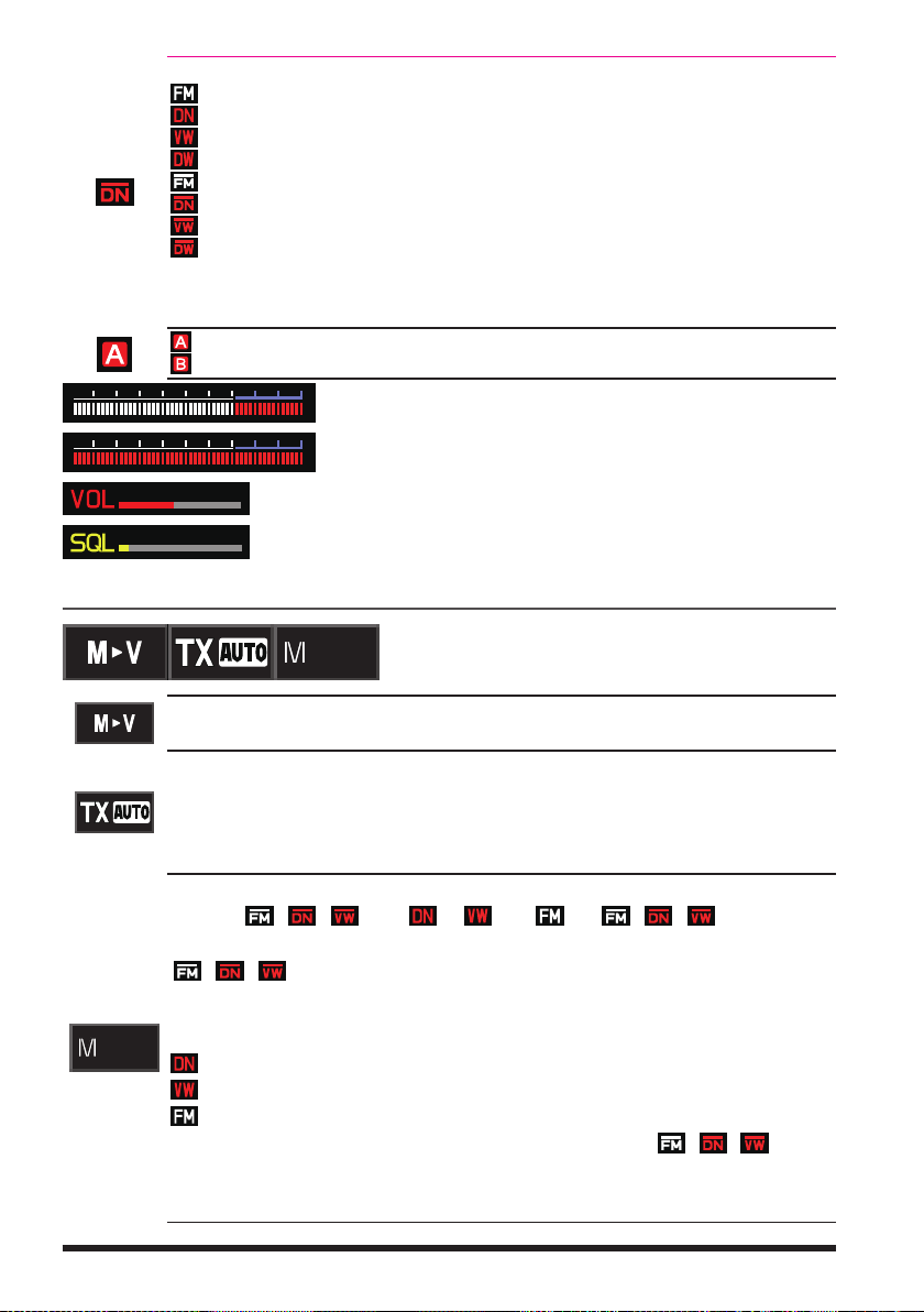
Touch Screen Display ................................... 6
Safety Precautions (Be Sure to Read)........ 12
Supplied Accessories and Options ............ 15
Supplied Accessories.................................. 15
Available Options......................................... 15
Preparation.................................................... 16
Installing the Antenna.................................. 16
Installing the Battery Pack .......................... 16
Attaching the Quick Release Holster .......... 16
Attaching the Belt Clip................................. 16
Charging the Battery Pack........................... 17
Charging the Battery Pack using
the Battery Charger (SAD-25)... 17
Charging the Battery Pack using
the Rapid Charger (CD-41) ... 17
External Power Supply................................. 18
Connecting an External Power Supply
for Use in a Vehicle ... 18
Connecting to an External Power Supply
Using a Power Cable... 18
Using a microSD Memory Card................... 18
Usable microSD Memory Cards ................. 18
Mounting and Dismounting
microSD Memory Card...... 18
Formatting a microSD Memory Card.......... 19
Operation....................................................... 20
Turning the Transceiver ON ........................ 20
Adjusting the Volume Level......................... 20
Adjusting the squelch setting ...................... 21
Toggling the Operating Band ...................... 21
Selecting a Frequency Band .......................22
Tuning to a Frequency.................................22
Changing the Frequency Step..................... 23
Selecting the Communication Mode........... 23
Transmission ............................................... 24
Changing the Transmit Power Level ........... 25
Locking Keys and DIAL knob ...................... 25
Using the convenient Digital C4FM feature
... 26
About the Digital Group ID (DG-ID) feature
... 26
Communicating with the DG-ID feature...... 26
Repeater Operation ...................................... 29
Communicating Via the Repeater............... 29
Using the Memory ........................................ 30
Registering to Memory Channels................30
Recalling a Memory Channel...................... 31
Recall only memories in the same frequency
band (Band) using the
memory auto grouping (MAG) function....... 31
Clearing Memories ...................................... 32
Restored erased memory............................ 32
Using Memory Tag ...................................... 32
Recalling the Home Channels.....................33
Changing the Home Channel Frequency....33
Memory Channel List .................................. 33
Split Memory ............................................... 33
Using Memory Bank....................................33
Memory Only Mode .....................................33
PMG (Primary Memory Group
Activity Monitor) ........... 34
Register the frequency with PMG ...............34
Touch the bar graph to switch the frequency
... 35
Unregister the channel (frequency)
registered in PMG..... 35
Disable the PMG function ........................... 35
CAM (Channel Activity Monitor) function ... 36
Register memory channel to CAM group.... 36
Using the CAM function ..............................38
Touch the bar graph to switch the frequency
...38
Change the displayed CAM group .............. 38
Delete a registered memory channel
from CAM group ...39
Delete all the contents
in the CAM group at once............... 40
Changing the name (tag) of CAM group ..... 40
Disable the CAM function............................ 41
Band Scope................................................... 42
Scanning Function ....................................... 43
VFO Scan ....................................................43
Memory Channel Scanning......................... 43
Setting the Receive Operation
When Scanning Stops........ 44
Weather Alert Scan .....................................44
Skip Memory Channels, and
Specied Memory Channels...........45
Programmable Memory scan (PMS)...........45
Dual Receive (D.RCV) feature ....................45
Convenient Functions.................................. 46
Bluetooth®Operation...................................46
VOX Operation ............................................ 50
Convenient Preset Receiver
Memory Channels ............. 52
Using the Voice Recording.......................... 56
Taking Pictures (Snapshot Function) ..........58
Contents

1
GPS Function .............................................. 59
WIRES-X function ....................................... 60
APRS (Automatic Packet
Reporting System) function.........60
Tone squelch feature................................... 61
Digital Code squelch (DCS) feature............ 61
New PAGER (EPCS) feature....................... 61
Digital Personal ID (DP-ID) feature............. 61
Using Setup Menu ........................................ 62
Setup Menu Operation ................................ 62
Tables of Setup Menu Operations............... 63
Restoring to Defaults (Reset)...................... 69
All Reset ......................................................69
Setup Menu Reset.......................................69
Text input screen .......................................... 70
............................................... 72
YAESU LIMITED WARRANTY ...................... 74

2
Introduction
Features of the Yaesu FT5DR/DE Transceiver.
mDigital communication using Yaesu (C4FM (Quaternary FSK) system).
mEquipped with AMS (Automatic Mode Select) Function.
The AMS (Automatic Mode Select) feature automatically selects the analog FM and
C4FM digital modes, according to the signal of the other station.
mThe DG-ID (Digital Group ID) feature, and the Group Monitor (GM) feature enable au-
tomatically locating, and communicating with other stations within contact range, that
have the matching DG-ID number, (Group ID number from 00 to 99).
mFull color 320x240 dot LCD, high resolution TFT touch panel display.
The communication status and settings of the FT5DR/DE are displayed in a straight-
forward manner, achieving excellent operability.
mEquipped with Bluetooth®function as standard.
Supports hands-free communication using the optional Bluetooth®headset SSM-
BT10 or a commercially available product.
mWIRES-X connection support.
mSupports WIRES-X portable digital node function.
mEquipped with GM function.
mDigital Personal ID (DP-ID) feature.
mSimultaneous reception of two separate frequencies, on different bands, or within the
same band (V+V/U+U).
mWide-band reception (520kHz to 999.995MHz) (USA Cellular Blocked)).
mWaterproof design equivalent to IPX7, which protects the transceiver from rain and
splashes.
mBuilt-in GPS unit permitting display of the current location and heading information.
mLarge-capacity 1256 memory channels.
mThe Memory Auto Grouping (MAG) function allows automatic grouping and recalling
only memory channels in the same frequency band.
mRegister frequently used frequencies into the PMG (Primary Memory Group
Activity Monitor), and then pressing the [PMG] key will display the registered fre-
quency status (signal strength) in a bar graph (up to 5 channels). You can instantly
move to that channel by simply touching the bar graph (TOUCH & GO Operation).
mDisplay memory tags comprised of up to 16 alpha/numeric characters.
mConvenient reception of preset receiver memory channels.
mA wide variety of scan features.
mReady for APRS®communication with world standard 1200 / 9600bps AX25 modem
(B-band only).
mHigh-resolution band scope that displays 79 channels.
mSmart Navigation function.
mSnapshot function (optional camera/microphone MH-85A11U is required).
m
A variety of individual Selective Calling functions (Tone Squelch (CTCSS) and DCS
etc.).
mCompatible with microSD memory cards.
Thank you for purchasing the FT5DR/DE Transceiver. We urge you to read this manual
in its entirety, and also the Advance Manual (available for download on the Yaesu web-
site), to gain a full understanding of the amazing capability of the exciting new FT5DR/
DE Transceiver.
WIRES-X, GM function and APRS instruction manuals are not included in the product
package. They are available and may be downloaded from the Yaesu.com website.
The Bluetooth®wordmark and logo are registered trademarks owned by Bluetooth SIG,
Inc. and are used under license by Yaesu Musen Co., Ltd.

3
①Turning the Power ON
Install the charged battery pack and then
press and hold the Power switch.
②Inputting the Call sign
When turning the power ON for the first
time after purchasing, input the call sign of
your own station.
Input call sign may be changed from Setup
Menu [CALLSIGN] (page 68).
1. When turning the power ON for the first
time after purchasing, the call sign input
screen will be displayed.
Please enter your
Callsign.
(Max 10 letters)
2. Press the [F] key.
3. Input the call sign.
Rotate the DIAL knob to select each
character.
Touch to move the cursor to the
right.
4. Repeat step 3 to input the remaining
call sign characters.
Touch to move the cursor to the left.
Touch to erase the character at the
cursor position.
5. Press the PTT switch to conclude input-
ting.
Normal operation (VFO Mode) screen
will be displayed.
③Selecting the Operating Band
Press the [BAND] key.
④Tuning the frequency
Rotate the DIAL knob.
⑤Adjusting the volume
Rotate the VOL knob to adjust the volume
to a comfortable level.
⑥Adjusting the squelch setting
The squelch level may be adjusted to mute
the background noise when no signal is
received.
1. Press the SQL key.
2. Rotate the VOL knob to adjust the
squelch to a level at which the back-
ground noise is muted.
* When the squelch level is increased,
the noise is more likely to be silenced,
but it may become more difficult to
receive weak signals.
3. Press the SQL key to save the setting.
⑦Selecting the
Communication Mode
The communication mode is automatically
selected to correspond to the signal being
received.
Touch [MODE] to manually select the com-
munication mode.
⑧
Transmitting/Receiving Signals
Transmitting
While pressing and holding the PTT
switch, speak into the microphone.
Receiving
Release the PTT to return to receive
mode.
Set the Bluetooth®function
The FT5DR/DE equipped with the Blue-
tooth function. To use a Bluetooth®head-
set, refer to “Bluetooth®Operation” on
page 46 for setting.
Quick Guide

4
Controls & Connections
Transceiver
⑥
⑧
⑨
⑩
GPS Antenna
Antenna jack (SMA)
①
TX/BUSY LED
②
PTT Switch
③
MONI/T-CALL
key
④
SQL key
⑤
Power( )Switch
Battery Pack
DIAL knob
VOL knob
Full Color
Touch screen
display
Operation Keys
Speaker
microSD memory
card slot
DATA Terminal
MIC/SP jack
EXT DC IN jack
⑦
TX/BUSY LED
Lights blue (C4FM digital) or green (Analog
FM) during receive and lights red during
transmit. Blinks while receiving a signal that
does not match the DG-ID or similar tones.
PTT Switch
Press and hold the PTT switch to transmit,
and release it to receive.
MONI/T-CALL key
Press to return to the previous screen.
USA/Asian version
Press the MONI/T-CALL key to open the
squelch.
European version
Press the MONI/T-CALL key to activate
the T-CALL (1750 Hz).
SQL key
Press the SQL switch, then rotate the VOL
knob to adjust the squelch level.
Power (Lock) Switch
• When the power is OFF, press and hold
this switch to turn the Power ON.
• When the power is ON, press and hold
the switch again to turn the Power OFF.
• When the power is ON, press this button
briefly to engage, or release the key lock.
DIAL knob
Rotate the DIAL Knob to change the fre-
quency or select a memory channel.
VOL knob
Rotate the VOL Knob to adjust the audio
volume level.
MIC/SP jack*
Connect the optional speaker microphone
or earpiece microphone to this jack.
When an external microphone or cable is
connected, the dust and splash protection
does not function.
Do not connect any microphone which
is not specified by Yaesu.
DATA Terminal*
• Connect the optional camera-equipped
microphone (MH-85A11U) to this terminal.
• To use the clone function, connect to an-
other FT5DR/DE with an optional clone
cable (CT-168).
• When updating the firmware, connect to a
PC using a USB cable.
* For instructions to update the firmware,
access the Yaesu Website.
• An external GPS may be connected to
this terminal.
microSD memory card slot*
EXT DC IN jack*
• When charging the battery pack, connect
the battery charger (SAD-25) to this jack.
• Connect an external power supply adapter
with a cigarette lighter plug (SDD-13) or an
external power cable (E-DC-6) to this jack.
Do not connect any battery charger
which is not specified by Yaesu.
* When the included antenna and battery pack
are installed and the MIC/SP jack, DATA ter-
minal, microSD card slot and EXT DC IN jack
are securely covered with rubber caps, the
FT5DR/DE meets the waterproofing perfor-
mance conforming to IPX7.

5
Operation Keys
Press Press and Hold
F key Pressing each time switches between
function screen and normal screen.
Press and hold for over one second to
enter Setup Menu.
A/B key Pressing each time switches between
A-band and B-band.
Press and hold for over one second
to switch between the Dual Band
Receive mode and the Mono Band
Receive mode.
BAND key Pressing each time increases the fre-
quency band. -
key Press to turn the GM function ON/
OFF.
In normal mode, press and hold for
over one second to start WIRES-X.
When WIRES-X is activated, press
and hold for over one second to return
to the normal mode.
V/Mkey Pressing each time switches between
VFO mode and memory mode.
Press and hold for over one second to
write to memory.
PMGkey
Pressing each time switches between
PMG (Primary Memory Group Activity
Monitor) mode and memory or VFO
mode.
Press and hold for over one second to
writing to PMG memory.
BACK key Return to the previous screen. -
Changing the Transceiver settings
1. Press and hold the [F] key.
The SETUP MENU screen will be displayed.
2. Touch the desired item in Setup Menu.
The Sub-menu screen will be displayed.
May also be operated by rotating the DIAL knob
to select the desired item in Setup Menu, and then
press the [F] key.
3. Press the PTT switch to save the settings and return
to normal operation.
Press the [BACK] key to save the settings and return
to the previous screen.

6
Touch Screen Display
Battery condition
Displays mode
Squelch/Volume Bar Graph (B-band)
Displays operation mode
Squelch/Volume Bar Graph (A-band)
Display of settings such as DG-ID/TONE
Communication Mode
A-band display area
B-band display area
A-band icon
LOCK
Lights when the mute Function is active
Lights when Auto Power Off is active
Lights when GPS Log Function is enabled
Lights when the Voice memory function is enabled
Lights when a microSD memory card is inserted
Lights when Bluetooth function is active
Lights when GPS is acquired
Lights when DTMF function is enabled
Communication mode selection (AMS/DN/VW/FM)
Communication mode selection at AMS (TX AUTO/TX FM/TX DN)
Touch and hold: Moving Memory Data to the VFO register
B-band icon
Lights when AF DUAL Function is enabled
Status Bar
The battery condition is displayed in 8 steps.
: Full battery power
: Battery is depleted. Charge battery.
: (When blinking) Charge battery immediately.
: Charging (displayed when the power is ON).
Appears when the lock function is enabled.
Appears when the Mute function for B-band is enabled.
Appears when the AF DUAL function is enabled.
Appears when the APO (Automatic Power-Off) function is enabled.
Appears when the DTMF Autodialer function is activated.
Appears when the Built-in GPS function is activated.
Appears: Satellites are acquired.
Blinks: Satellites cannot be acquired.
Appears when the Voice recording function is activated (About 3 seconds after the
squelch closes, the recording pauses and a “ ” appears.).
Appears when the GPS Log function is enabled.
Appears when a microSD card is inserted.
Appears when the Bluetooth®function is activated.
Appears: Bluetooth®device is connected.
Blinks: Bluetooth®device not connected.

7
A-band / B-band display area
A-band / B-band display modes
: VFO mode
: PMG mode (Recalls only the frequencies registered in PMG)
: Memory mode (The numeric is the memory channel number)
Press the BAND key while in memory mode, the MAG function can automat-
ically recall memory channels in groups for each of the following bands: (For
details, refer to “Using the Memory” on page 30.)
/ / / / / / /
: Home Channel
VDR : VFO Dual Receive (VFO ↔Priority Memory Channel)
MDR :
Memory Channel Dual Receive (Memory Channel
↔
Priority Memory Channel)
HDR : HOME Channel Dual Receive (HOME Channel ↔Priority Memory Channel)
: Repeater minus (-) shift
: Repeater plus (+) shift
: Split operation
Specified Memory Channel (Specify that only designated memory channels are
scanned during memory scanning.)
Skip Memory Channel (Permits designating unwanted channels to be skipped during
scanning.)
Priority Memory Channel (The transceiver checks for signals on the frequency regis-
tered to the selected Priority Memory Channel, once every 5 seconds.)
ATT (attenuator) function (When the desired signal is extremely strong, activate the
attenuator to reduce the incoming signal from the antenna.)
Bell function is activated.
TX/RX DG-ID is displayed
TXnn (The transmit DG-ID number), RXnn (The receive DG-ID number)
Squelch type is displayed (For additional details, refer to the Advanced Manual.)
: Tone Encoder (tone frequency is displayed)
: Tone Squelch (tone frequency is displayed)
: DCS (Digital Code Squelch) (DCS code is displayed)
: Reverse Tone (tone frequency is displayed)
: Signal Squelch
: Pager (EPCS)
The following can be set when the squelch expansion (see page 64) is on.
: Send the DCS code only during transmission.
: Send the CTCSS tone signal during transmit, and wait for the DCS code in
receive mode. (tone frequency is displayed)
: Send the DCS code during transmit, and wait for the CTCSS tone signal in
receive mode. (tone frequency is displayed)

8
Displays the operating mode (Digital mode is indicated by a red icon)
: FM (Analog) mode
: Normal digital mode (digital mode using C4FM modulation)
: Wide digital mode (digital mode using C4FM modulation)
: Data FR mode (data communication mode using C4FM modulation)
: AMS (Automatic Mode Select) FM (Analog) mode
: AMS (Automatic Mode Select) DN mode
: AMS (Automatic Mode Select) VW mode
: AMS (Automatic Mode Select) DW mode
When AMS (Automatic Mode Select) function is activated, indicator is shown with a
bar appearing above the mode. The transceiver automatically switches to the DW
mode during image transmission.
: A-band icon
: B-band icon
: S meter (Displays received signal strength in 10 levels)
: PO meter (Displays transmit output in 4 levels when transmitting)
: Volume level
: SQL level
Touch keys display area
MODEMODE
Touch and hold: Moving Memory Data to the VFO register.
Each touch steps the transmit communication mode as follows:
TX (AUTO) TX (FM) TX (DN) TX (AUTO) • • •
TX (AUTO): Automatically selects the transmit mode to correspond to the received signal.
TX (FM): Always transmits in the analog FM mode.
TX (DN): Always transmits in the digital (DN) mode.
MODEMODE
Each touch steps the communication mode as follows:
( / / )*1*2( / / )*1• • •
The current communication mode is displayed on the upper right of the frequency.
/ / *1:
AMS function operation (A bar is displayed at the top of the communication
mode icon, and the AMS function automatically displays the selected commu-
nication mode.)
:V/D Mode (Voice/Data simultaneous transmission mode)
*2:Wide digital mode (high-quality digital communication)
:FM (Analog) mode
*1 The AMS (Automatic Mode Select) function displays one of the / / icons for
the automatically selected communication mode.
*2 When the Setup Menu item [TX/RX] [2 DIGITAL] [4 DIGITAL VW] is set to “ON”
(factory default is “OFF”), the Voice FR (VW) may be selected.

9
●Dual Band Screen
A-band and B-band are displayed in a top-down fashion.
Both bands are received simultaneously.
Touch and hold the frequency of the operation band
(white display) to display the numeric keypad screen for
frequency input.
Touch the sub-band (gray display) frequency to change
the operation band.
When both the operation band and the sub-band are re-
ceiving signals at the same time, the audio on the sub-
band receiver is automatically muted. Setup Menu:
[TX/
RX]
[3 AUDIO]
[2 MUTE]
: Allows setting the
muting level.
Press and hold the [A/B] key.
●Mono Band Screen
A-band or B-band is displayed.
Receives only the displayed band.
MODEMODE
Touch and hold the frequency to display the numeric
keypad screen for frequency input.
The memory tag and battery voltage etc. are displayed
on the lower segment.
●Function Menu Screen (Press the [F ] key)
Press the [F] key to displays the function menu screen.
Press the [BACK] key to return to the previous screen.
There are two function menus. Touch [FWD ] or [BACK
] at the bottom right of the
display to switch the screens.
Depending on the communication mode and settings, some functions may not operate
when the Menu item is touched.
Function Menu Screen 1
Touch
Touch
Function Menu Screen 2

10
●PGM (Primary Memory Group Activity Monitor) Screen (Press the [PMG] key)
Up to 5 frequencies registered in PMG are displayed, and the signal strength received
by each channel is displayed as a bar graph.
YAESU
Touch the bar graph to instantly switch the receiver to
that frequency.
Information on the selected channel is displayed at the
top of the screen, and you can transmit immediately by
pressing PTT.
●CAM (Channel Activity Monitor) Screen (Press the [F]key Touch [CAM])
Frequencies that are often used with friends can be registered to the CAM group mem-
ory channels, and then displayed on the CAM screen. The signal status and strength of
each channel in the selected group are shown in a bar graph.
YAESU
Touch the bar graph to instantly switch the receiver to
that frequency.
CAM Group: Up to 10 groups, with up to 5 memory
chan- nels each, can be registered in each group.
●Band Scope Screen (Press the [F]key Touch [SCOPE])
In VFO mode, the Band Scope searches the channels above and below the center re-
ceive frequency at high speed. The signal strengths are displayed on a graph, so the
presence or absence of a signal on any channel is easily noted.
The frequency may be changed by turning the DIAL
knob.
Touch [SEARCH] or [STOP] to begin or stop the search.
The number of channels to search in Band Scope may
be set to 19, 39 or 79. (See “Change the number of
channels displayed” page 42).
To end the Band Scope function, press the [BACK] key.
●GM (Group Monitor) Screen (Press the [GM/X]key)
Automatically listens for stations operating with GM function on the same frequency,
that are within the communication range, and displays the call sign, direction, distance,
within / outside. For details, refer to the separate GM Instruction Manual which is avail-
able on the Yaesu website.
The call signs of the stations that can communicate is
displayed in white characters.
The call signs of stations outside the sphere of commu-
nications are displayed in gray characters.
Touch [APL], to display the positions of multiple mem-
ber stations on the compass screen, centered on your
own station.
Touch [LOG] to view previously sent or received mes-
sages and photos.
To end the GM function, press the [GM] key.

11
●AF DUAL Screen (Press the [F]key Touch [A.DUAL])
While receiving and listening to a radio broadcast, the A-band and B-band may also be
monitored simultaneously for activity.
When a signal is received on A-band or B-band, the
broadcast audio is muted and the A or B band audio is
heard.
To end the AF DUAL function, press the [BACK] key.
●BACKTRACK Screen (Press the [F]key Touch [DISP])
The backtrack screen, or the GPS information screen, whichever was displayed last, will
be displayed.
Real-time navigation function
Touch [ ] at the top left of the screen to display the position and direction of the part-
ner station in real time during communication in C4FM digital V/D mode. (The signal
of the partner station must contain location information.)
BACKTRACK function
May register the departure point etc. up to 3 places (“H”, “L1”, “L2”) in advance and
display the distance from the current location to the registered point in real time.
●GPS Information Screen (Press the [F]key Touch [DISP])
The backtrack screen, or the GPS information screen, whichever was displayed last, will
be displayed. The GPS satellites status and numbers are shown.
The following information is displayed.
Direction and elevation of satellites, and their signal strengths
Current time and date ●Current latitude and longitude
Moving Speed ●Altitude of current location
Backtrack Screen
JA1YOE-123
Touch the screen (other
than the Touch keys).
GPS Information Screen
●SETUP MENU Screen (Press and hold the [F]key)
Setup Menu allows selecting various functions from the displayed list and setting the
parameters of each function according individual preferences.
Press the PTT switch or press the [BACK] key several
times to exit the Setup Menu.

12
Safety Precautions (Be Sure to Read)
Be sure to read these important precautions, and use this product safely.
Yaesu is not liable for any failures or problems caused by the use or misuse of this prod-
uct by the purchaser or any third party. Also, Yaesu is not liable for damages caused
through the use of this product by the purchaser or any third party, except in cases
where ordered to pay damages under the laws.
Types and meanings of the marks
DANGER This mark indicates an eminently hazardous situation, which, if not avoided,
could result in death or serious injury.
WARNING This mark indicates a potentially hazardous situation, which, if not avoided,
could result in death or serious injury.
CAUTION This mark indicates a potentially hazardous situation, which, if not avoided,
may result in minor or moderate injury or only property damage.
Types and meanings of symbols
These symbols signify prohibited actions, which must not be done to use this product safely.
For example: indicates that the product should not be disassembled.
These symbols signify required actions, which must be done to use this product safely.
For example:
indicates that the power plug should be disconnected.
DANGER
WARNING
Do not disassemble or make any alteration
to this product.
An injury, electric shock, or failure may result.
Do not handle the battery pack or charger
with wet hands. Do not insert or remove the
power plug with wet hands.
An injury, leak, fire, or failure may result.
Do not power this transceiver with a voltage
other than the specified power supply volt-
age.
A fire, electric shock, or damage may result.
Keep the terminals of the battery pack clean.
If terminal contacts are dirty or corroded, a fire,
leak, overheating, explosion, or ignition can re-
sult.
Do not use this product in an area where RF
transmitters are prohibited, e.g., inside of a
hospital, airplane, or train.
This product can affect electronic or medical de-
vices.
Do not transmit with this device while carry-
ing or using a medical appliance such as a
cardiac pacemaker. When transmitting, use
an external antenna and keep as far as pos-
sible away from the external antenna.
The radio wave emitted by the transmitter can
cause the medical device to malfunction and
result in injury or death.
Do not transmit with this device in a crowded
place for the safety of persons using a medi-
cal device such as a cardiac pacemaker.
The radio wave emitted from this product can
cause the medical device to malfunction and
result in injury or death.
Do not use this product or the battery char-
ger anywhere inflammable gas is produced.
A fire or explosion can occur.
If thunder and lightening develop nearby
when an external antenna is used, immediate-
ly turn this transceiver OFF, and disconnect
the external antenna from it.
A fire, electrical shock, or damage may result.
Do not use this product while riding a bicycle
or driving a car. Accidents can result.
Be sure to stop the bicycle or car at a safe place
before using this product.
Do not touch any material leaking from the
LCD display or the battery pack with bare
hands.
The chemical may adhere to your skin or enter
your eye, and cause chemical burns. In such a
case, consult the doctor immediately.
Do not solder or short-circuit the terminals
of the battery pack.
A fire, leak, overheating, explosion, or ignition
may result.
Do not carry the battery pack together with a
necklace, hairpin, or small metal objects. A short
circuit can result.

13
If smoke or a strange odor is emitted from
the main body, battery pack, or battery char-
ger, immediately turn the transceiver off;
remove the battery pack, and remove the
power plug from the outlet.
A fire, chemical leak, overheating, component
damage, ignition, or failure may result. Contact
the dealer from which you purchased this product
or Yaesu.
Do not bend, twist, pull, heat or modify the
power cord and connection cables in an un-
reasonable manner.
This may cut or damage the cables and result in
fire, electric shock and equipment failure.
Do not pull the cable when plugging and
unplugging the power cord and connection
cables.
Always hold the plug or connector when unplug-
ging; if not, a fire, electric shock and equipment
failure may result.
Do not use the device when the power cord
and connection cables are damaged, or when
the DC power connector cannot be plugged
in tightly.
Contact Yaesu or the retail store where this
transceiver was purchased for assistance, as
this may result in fire, electric shock and equip-
ment failure.
Do not install the transceiver or the wire ca-
bles near the automobile air bags.
In case of an accident, the transceiver may
interfere with air bag deployment and result in
extreme injury. The wire cables may also cause
the air bag to malfunction.
Do not make very long transmissions.
The main body of the transceiver may overheat,
resulting in component failure or operator burns.
Do not place the transceiver in wet or damp
areas (e.g. near a humidifier).
This may result in fire, electric shock and equip-
ment failure.
Do not use DC power cords other than the
one enclosed or specified.
This may result in fire, electric shock and equip-
ment malfunctions.
When connecting a DC power cord, be cer-
tain the positive and negative polarities are
correct.
Reverse connection will result in equipment
damage.
When transmitting, keep the transceiver at
least 5.0 mm (3/16 inch) away from your body.
Use only the supplied antenna. Do not use
modified or damaged antennas.
Disconnect the power cord and connection
cables before installing separately sold ac-
cessory items.
This may result in fire, electric shock and equip-
ment failure.
Follow the instructions provided when in-
stalling items sold separately.
This may result in fire, electric shock and equip-
ment failure.
Use only the provided or specified screws.
Using screws of a different size, may result in
fire, electric shock and component damage.
Do not place the transceiver in a confined
space, such as a bookshelf which is not ven-
tilated well.
This may result in overheating and fire, electric
shock and equipment failure.
Do not operate the transceiver on a carpet or
a blanket.
This may result in overheating and fire, electric
shock and equipment failure.
If a foreign substance is spilled into the
transceiver, turn it OFF immediately and re-
move the power plug from the outlet.
If used as it is, a fire, electrical shock, or dam-
age may result.
CAUTION
Do not place the transceiver on an unsteady
or sloping surface, or in a location with ex-
treme vibration.
The transceiver may fall or drop, resulting in fire,
injury and equipment damage.
Do not place this transceiver in a humid or
dusty place.
A fire or failure may result.
Do not use the transceiver near the radio re-
lay equipment.
Transmissions may affect radio communica-
tion.
Do not wipe the case using thinner and ben-
zene etc.
Use only a soft, dry cloth to wipe stains from the
case.
Do not throw the transceiver, or subject it to
strong impact forces.
Physical abuse may result in component dam-
age and equipment failure.
If the transceiver will not be used for an extend-
ed period, turn it OFF and remove the battery
pack for safety.
Keep magnetic cards and videotapes away
from the transceiver.
The data recorded on cash cards or videotapes
may be erased.
Do not place this transceiver in direct sun-
light or near a heater.
The case may be deformed or discolored.
Do not operate the transceiver near the TV or
radio.
Radio disturbance can occur in the transceiver,
the TV, or the radio.

14
About Waterproofing Feature Conforming to IPX7
When the included antenna and battery pack are installed and the MIC/SP jack, EXT
DC IN jack, DATA terminal, and microSD slot are securely covered with rubber caps,
this product is moisture and splash resistant. To ensure continued waterproofing pro-
tection, be sure to check the following points before use.
mCheck for damages, deterioration, and dirt.
Antenna rubber, key switch rubber, MIC/SP jack, EXT DC IN jack, DATA terminal, microSD
slot rubber cap, and battery pack joint.
mCleaning
When this product is contaminated with seawater, sand, or dirt, rinse with fresh water, and
then wipe with a dry cloth immediately.
mRecommended maintenance interval
To ensure continued water resistance and optimal performance, it is recommended that
maintenance be performed annually, or when any damage or deterioration is found. Note that
the maintenance service is subject to fees.
mDo not immerse this product in the following liquids:
Sea, pool, hot spring, water containing soap, detergent, or bath additive, alcohol, or chemi-
cals.
mDo not leave this product for an extended time in the following places:
Bathroom, kitchen, or humid place
mOther precautions
Since this product is not totally waterproof, it cannot be immersed in water.
Be sure to check with the manufacturer of
any hybrid or fuel-saving automobile regard-
ing use of the transceiver in that car.
Noise generated by an onboard electrical device
(inverter, etc.)can disrupt the normal operation
of the transceiver.
Do not transmit near the television and radio.
Transmissions may cause electromagnetic inter-
ference.
While transmitting, keep the antenna as far
from you as possible.
Long-time exposure to electromagnetic waves
may have a negative impact on your health.
Do not dangle or throw the transceiver by
holding its antenna.
This may injure others and may also result in
damage and failure of the transceiver.
Do not use the transceiver in a crowded
place.
The antenna may strike others and result in an
injury.
Keep this product out of the reach of children.
Injury to the child, or damage to the transceiver
may result.
Do not use any products other than the spec-
ified options and accessories.
Failure or miss operation may result.
Install the hand strap and belt clip securely.
Improper installation may cause the FT5DR/
FT5DE to fall or drop, resulting in an injury or
damage.
This product has a waterproof structure and
conforms to “IPX7” when the included anten-
na and battery pack are installed and rubber
caps are securely attached to the MIC/SP
jack, EXT DC IN jack, and DATA terminal. If
this transceiver gets wet, dry it with a soft
cloth, do not leave it exposed to the mois-
ture.
Exposure to excessive moisture may degrade
the transceiver performance, shorten its life, or
cause a failure or electrical shock.
Before discarding a depleted battery pack, affix
tape or insulating covering to its terminals.
Do not use at extremely low atmospheric pres-
sure.

15
Supplied Accessories and Options
Supplied Accessories
• Rechargeable Li-Ion Battery Pack (7.2V, 2,200mAh) SBR-14LI
• Battery Charger SAD-25
• Antenna
• Belt Clip
• Quick Release Holster SHB-26BK
• USB Cable
• Operating Manual (This Manual)
• SBR-14LI Manual
• Battery Pack protective cap
If any item is missing, contact the dealer from which you purchased the transceiver.
Available Options
• Speaker Microphone with Snapshot camera MH-85A11U
• Speaker / Microphone SSM-17A
• Earpiece Microphone SSM-57A
• VOX Headset SSM-63A
• Bluetooth®Headset SSM-BT10
• Microphone Adapter CT-44
• DC Cable with and Cigarette-Lighter Plug SDD-13
• DC Cable E-DC-6
• Quick Release Holster SHB-26BK
• Soft Case SHC-40
• 3x “AA” Cell Battery Case FBA-39
• Li-Ion Battery Packs (7.2V, 2,200mAh) SBR-14LI
• Li-Ion Battery Packs (7.4V, 1,100mAh) FNB-101LI
• Battery Charger SAD-25
• Rapid Charger CD-41
• PC connection cable SCU-39
• Cloning Cable CT-168
• PC connection cable CT-169
• Data Cable CT-170
• Data cable (2.5) CT-176
• Belt Clip SHB-13
• BNC-to-SMA Adapter (BNCJ-SMAP) CN-3

16
Preparation
Installing the Antenna
Turn the antenna clockwise until it is secured.
• Do not hold or twist the upper part of the antenna
when installing or removing it. To do so may break the
conductors inside the antenna.
• Do not key the transmit without installing the antenna. The
transmitter components may be damaged.
Hold the thick base
of the antenna
Installing the Battery Pack
1. Insert the bottom tabs of the battery pack in the slots on
the back side lower part of the transceiver.
2. Push the battery in until the battery latches click securely.
Charge the battery pack before using the transceiver for the
first time after purchase, or when it has not been used for a
long period time.
Risk of explosion if battery is replaced by an incorrect type.
Dispose of used batteries according to the instructions
Battery Latches
●Removing the Battery Pack
While pressing down the latches, remove the battery pack.
Attaching the Quick Release Holster
Attach the quick release holster using the supplied screws (two).
Supplied screws (black)
for the Quick release Holster
Attaching the Belt Clip
Attach the belt clip using the supplied screws (two).
Supplied screws (silver)
for the Belt Clip
Be sure to use the supplied screws when attaching the belt clip. If any other screws are used, the
belt clip cannot be secured firmly to the battery pack and the transceiver may drop off together
with the battery pack; the transceiver and battery pack may fall off, breakage and other damage.
To remove the holster,
press the release knob.
②Press holster firmly
until you hear the
latch click.
①
Insert the bottom tabs of the Quick Release Holster in the
slots on the bottom of the FT5DR/DE

17
Charging the Battery Pack
Charging the Battery Pack using the Battery Charger (SAD-25)
Using the supplied battery charger (SAD-25), it takes about 9 hours* to charge the SBR-
14LI battery pack fully.
*Depending on the battery status, the charging time might be increased
1. Referring to the figure at the right, connect the
battery charger plugs.
When the battery is being charged, the TX/BUSY
Indicator of the A-band lights red, and “Now
Charging” is displayed. The charge level is indi-
cated by a bar graph.
2. When charging is completed, the display will
change to indicate “CHGFUL” and the TX/BUSY
Indicator will light green.
While the transceiver power is ON, “ ” will ap-
pear on the display.
Battery charger
SAD-25 (supplied)
EXT DC IN jack
In the USA Version, the TX/BUSY LED is not lit when charging or when charging is complete.
When the charge is complete, the transceiver turns OFF after 3 minutes.
• If “CHGERR” appears on the LCD during the charging and the battery pack is not charged
after a lapse of 10 or more hours, stop charging the battery pack immediately. The battery
pack is presumed to be at the end of its service life, or defective. In this case, replace the
battery pack with a new one.
• Charge the battery pack within the temperature range from +41°F to +95°F (+5°C to
+35°C).
Charging the Battery Pack using the Rapid Charger (CD-41)
The optional Rapid Charger (CD-41) requires about 5 hours to charge the SBR-14LI
battery pack.
1. Insert the DC plug from the SAD-25 into the DC jack on the CD-41 rear panel, then
plug the SAD-25 into the AC line outlet.
2. Place the transceiver with battery pack attached or the battery pack alone into the
CD-41, charging will start and the red LED (CHARGING) of the CD-41 will light up.
3. When charging is complete, the red “CHARGING” indicator turns OFF and then the
green “FULL” indicator will light.
It may take some time for the green LED to turn ON after the red LED turns OFF.
●Approximate Operating Time and Remaining Charge Level Indication
Approximate operating time for the transceiver with the fully charged battery pack or
new AA alkaline batteries is as follows:
Band in Use
Digital: OFF
Battery pack
SBR-14LI
Battery pack
FNB-101LI
Battery
FBA-39
Amateur Band 144 MHz Band Approx. 9.5 hours Approx. 4.5 hours Approx. 12 hours
430 MHz Band Approx. 8 hours Approx. 4 hours Approx. 11 hours
The battery charge level calculations are based on an operating cycle of: Transmitting
6 seconds (5 W): Receiving 6 seconds (VOL Level 16): Stand By 48 seconds (RX SAVE
1:5)
The actual times the transceiver will operate as indicated in the above table, varies de-
pending on use, conditions, ambient temperature, etc.

18
External Power Supply
Connecting an External Power Supply for Use in a Vehicle
The optional DC Cable with Cigarette-Lighter plug (SDD-13) allows power to be supplied
from a motor vehicle type cigarette lighter socket.
Connecting to an External Power Supply Using a Power Cable
The optional DC cable (E-DC-6) allows the transceiver to be connected to an external
DC power supply.
Using a microSD Memory Card
Using a microSD memory card with the transceiver allows the following functions.
Backing up the transceiver data and information
Saving memory information
Voice recording/playback
Saving GPS log data
Saving image data captured with the optional camera-equipped microphone (MH-
85A11U)
Saving messages downloaded with the GM function or WIRES-X function
Usable microSD Memory Cards
This transceiver only supports the following capacity of microSD and microSDHD mem-
ory cards.
・ 2GB ・ 4GB ・ 8GB ・ 16GB
・ 32GB
• microSD memory cards formatted on other devices may not properly save information
when used with this transceiver. Format microSD memory cards again with this transceiver
when reusing memory cards formatted with another device.
• Do not remove the microSD memory card or turn the transceiver OFF, while saving data to
a microSD memory card is in progress.
Mounting and Dismounting microSD Memory Card
1. Press and hold the Power (Lock) switch to turn
the transceiver OFF.
2. Insert the microSD memory card into the card
slot until a clicking sound is heard (as shown in
the figure at the right).
3. Press and hold the Power (Lock) switch to turn
the transceiver ON.
When the memory card is properly detected,
“” lights on the display.
Contact surface
●Removing the microSD memory card
To remove the microSD memory card (inserted in step 2 above), push the memory card
in until a clicking sound is heard, then remove the memory card.
This manual suits for next models
2
Table of contents
Other Yaesu Transceiver manuals

Yaesu
Yaesu FT-80C - SERVICE User manual

Yaesu
Yaesu FT-277R User manual

Yaesu
Yaesu VX-3R User manual

Yaesu
Yaesu FTDX10 Manual

Yaesu
Yaesu FTM-300DR User manual

Yaesu
Yaesu FTDX101MP User manual

Yaesu
Yaesu FTA-250L User manual

Yaesu
Yaesu FTM-100DR User manual

Yaesu
Yaesu FT-101EE User manual

Yaesu
Yaesu FT-727R User manual

Yaesu
Yaesu FT5Dr User manual

Yaesu
Yaesu FT-2000 - MENU MODE LIST User manual

Yaesu
Yaesu FTM-500DR User manual

Yaesu
Yaesu FT-950 Technical manual

Yaesu
Yaesu FT5De User manual

Yaesu
Yaesu GX1280S User manual

Yaesu
Yaesu FT-980 Manual

Yaesu
Yaesu FTM-3207DR User manual

Yaesu
Yaesu FT-2400H User manual

Yaesu
Yaesu FT-707 User manual