Yaesu FTM-200DR User manual


Introduction ........................................................... 1
Quick Guide .......................................................... 2
Supplied Accessories and Options .................... 3
Supplied Accessories .......................................................... 3
Available Options ................................................................. 3
Basic Operation .................................................... 4
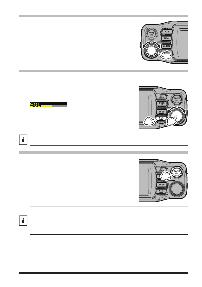
Turning the Transceiver ON ................................................ 4
Adjusting the volume ........................................................... 5
Adjusting the squelch level ................................................. 5
Selecting a Frequency Band .............................................. 5
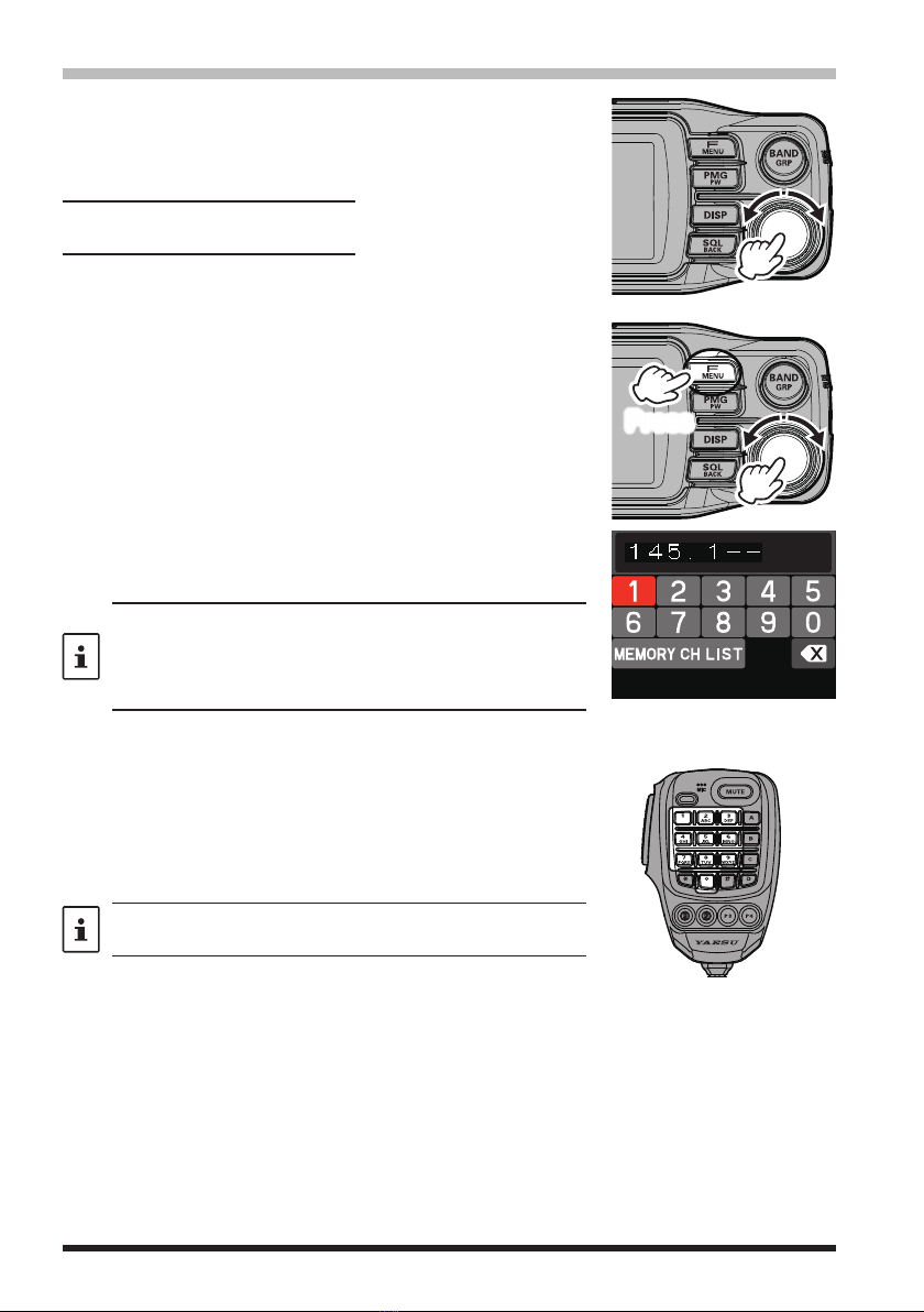
Tuning to a Frequency ......................................................... 6
Changing the operation band ............................................. 7
Transmitting .......................................................................... 7
Locking the Keys and DIAL knob ....................................... 7
Useful Functions .................................................. 8
1 CFL: Custom Function List .............................................. 8
2
PMG-SR (Single Receiver Primary Memory
Group Activity Monitor)
......... 9
3 Band Scope .................................................................... 10
4 Memory auto grouping (MAG) function ........................ 10
5 VFO Band skip function ................................................. 10
6 Memory channel VFO copy....................................... 10
Setup Menu List ................................................................. 11
Name and function of each component ........... 12
Panel (front) ........................................................................ 12
Panel (Left and right side) ................................................. 14
Panel (rear) ......................................................................... 14
Main body (Front) ............................................................... 15
Main body (rear) ................................................................. 15
Microphone (SSM-85D) .................................................... 16
Display ................................................................................ 18
Descriptions of Main Screens ........................................... 20
Safety Precautions (Be Sure to Read) .............. 23
Installing the Radio ............................................ 25
About the antenna ............................................................. 25
Connection of Antenna and Power Cables ..................... 25
Installing the transceiver ................................................... 26
Connecting the front panel to the main body .................. 26
Using a Micro SD Memory Card ........................ 27
Functions to use as needed .............................. 28
Selecting the Communication Mode ................................ 28
Fixing the Communication Mode ..................................... 29
Changing the Transmit Power Level ................................ 29
Setting the Skip Band ........................................................ 30
Changing the Frequency Step .......................................... 30
Change the frequency display color of the operation band
......... 30
Custom Function List ......................................... 31
Use the Function List ......................................................... 31
Registration to the Function List ....................................... 32
Cancel registration in the Function List ........................... 32
Using the convenient Digital C4FM features ... 33
About the Digital Group ID (DG-ID) feature .................... 33
Repeater Operation ............................................ 36
Using the Memory .............................................. 37
Writing to memory ............................................................. 37
Recall memory (There are three ways) ........................... 38
Recall only memories in the same frequency band
using the memory auto grouping (MAG) function ........... 40
Edit memory ....................................................................... 41
Recalling the Home Channels .......................................... 42
Changing the Home Channel Frequency ........................ 43
Split Memory ...................................................................... 43
PMG-SR (Single Receiver Primary
Memory Group) Activity Monitor ... 45
Register the frequency to PMG ........................................ 45
Call up the PMG screen .................................................... 45
Switch between Auto Mode and Manual Mode .............. 46
Auto Mode .......................................................................... 46
Operation of Auto Mode ....................................................................... 46
Manual Mode ..................................................................... 47
Operation of Manual Mode ................................................................. 47
Unregister the channel (frequency) registered in PMG
.......... 47
Scanning Function ............................................. 48
VFO Scan / Memory Scan ................................................ 48
Setting the Receive Operation When Scanning Stops
......... 48
Skip Memory Channels ..................................................... 49
Programmable Memory scan (PMS) ............................... 49
Convenience Features ....................................... 50
Bluetooth
®
Operation ......................................................... 50
Installing the Bluetooth
®
unit “BU-4” .................................................. 50
Pairing the Bluetooth
®
Headset ........................................................... 51
Activate Transmit by pressing the button on the Bluetooth
®
headset (when the VOX function is OFF) ............ 52
Hands-free VOX operation with a Bluetooth
®
headset
............ 52
VOX Operation ................................................................... 53
Setting VOX function ............................................................................ 53
Set the VOX (Voice Operated Transmit) delay time ........................ 54
Bluetooth
®
battery save function ........................................................ 54
Connect with another Bluetooth
®
headset ........................................ 55
Bluetooth
®
received audio output ....................................................... 56
Band Scope ........................................................................ 57
Dual Receive Function ...................................................... 58
Priority Scan .......................................................................................... 58
A-B Dual Receive ................................................................................. 58
Using the Voice Recorder ................................................. 59
Recording the receive audio ............................................................... 59
Setting the Recording function ........................................................... 60
Playback the recorded audio .............................................................. 61
Taking a Picture (Snapshot Function) .............................. 62
Taking pictures ...................................................................................... 63
Viewing the Saved Image .................................................................... 63
Deleting saved images ......................................................................... 64
Edit the tag (display name) of the saved image ................................ 64
GPS Function ..................................................................... 64
WIRES-X function ............................................................. 64
APRS function .................................................................. 64
Digital Personal ID (DP-ID) feature .................................. 65
Tone squelch feature ......................................................... 65
Digital Code squelch (DCS) feature ................................. 65
New PAGER (EPCS) feature ............................................ 65
Using Setup Menu .............................................. 66
Tables of Setup Menu Operations ..................... 67
Restoring to Defaults (Reset) ............................ 75
All Reset ............................................................................. 75
Memory Channels Reset .................................................. 75
APRS Reset ....................................................................... 75
Text input screen ................................................ 76
Specifications ..................................................... 77
Contents

1
Introduction
Features of the Yaesu FTM-200DR/DE Transceiver.
mDigital communication using Yaesu (C4FM (Quaternary FSK) system)
mEquipped with AMS (Automatic Mode Select) feature that automatically selects the
analog FM or the C4FM digital modes, according to the signal of the other station.
mThe Custom Function List (CFL) can be personalized by registering frequently used
functions (up to 8) from the 124 items Setup Menu. Functions and setting values are
then displayed in a list with one-touch operation of the [F MENU] key. Or you can easily
select and use the function with the DIAL knob.
mThe Single Receiver Primary Memory Group Activity Monitor (PMG-SR) function
can register up to 5 channels with the receive frequencies of the VFO or memory
channels by simply pressing and holding the [PMG PW] key. Press the [PMG PW] key
to scan the registered frequencies and display the reception status (signal strength)
in a real time bar graph. In auto mode, any channel with a signal is automatically
stopped and received. When operating on the currently selected channel, you can
press the PTT key or press the dial to switch to manual mode and fix the channel for
communication. When there is no signal in the selected channel, it scans again and
displays the reception status (signal strength) in real time.
m
With Memory Channel Band Auto Grouping (MAG). The memory channels are
automatically categorized in each band, so that memory channels can be quickly recalled.
mThe DG-ID (Digital Group ID) feature, and the Group Monitor (GM) feature enable
automatically locating, and communicating with other stations that are within contact
range and have the matching DG-ID number, (00 to 99).
mTwo-inch QVGA full-color TFT display with high-brightness and wide viewing angle.
mWide-band reception (108 MHz to 999.99 MHz) (USA Cellular Blocked)
mBuilt-in GPS unit permits display of the current location and heading information
m
Installation of the optional Bluetooth
®
BU-4 unit permits hands-free communication
using the optional Bluetooth
®
headset SSM-BT10 or a commercially available product.
mLarge-capacity 1104 memory channels
m3W Audio Power Speaker with a jack for the optional external speaker
mHeavy Duty-Heat Sink with FACC (Funnel Air-Convection Conductor)
mHigh speed band scope that displays 61 channels
mSmart Navigation function
mSnapshot function (optional camera/microphone MH-85A11U is required)
mWiRES-X Portable Digital Node or Fixed Node with HRI-200
mEquipped with digital GM (Group Monitor) function
mReady for APRS®communication with world standard 1200 / 9600bps AX25 modem
mDigital Personal ID (DP-ID) feature
mCompatible with microSD memory cards
Thank you for purchasing the FTM-200DR/DE Transceiver. We urge you to read this manual in its entirety, and
also the Advance Manual (available for download on the Yaesu website), to gain a full understanding of the
amazing capability of the exciting new FTM-200DR/DE Transceiver.
WIRES-X, GM function and APRS instruction manuals are not included in the product package. They are
available and may be downloaded from the Yaesu.com website.

2
Turn the Power ON
Press and hold the [POWER (LOCK)]
switch.
Input the Call sign
When turning the power ON for the first
time after purchasing, input the call sign of
your own station.
Input call sign may be changed from the
Setup Menu [118 CALLSIGN].
1. When turning the power ON for the first
time after purchasing, the call sign input
screen will be displayed.
Please enter
Your CALLSIGN
(Max 10 letters)
Press the Dial knob
2. Press the DIAL knob.
3. Input the call sign.
Rotate the DIAL knob to select each
character and then press the DIAL knob.
:
to move the cursor to the right
:
to move the cursor to the left
:
change to the numeric and symbol input
:
change to character input
:
delete the character left of the cursor
See “Text input screen” on page 76 to
input a call sign.
4. Repeat step 3 to input the remaining call
sign characters.
5. Press and hold the DIAL knob to con-
clude inputting.
Normal operation (VFO Mode) screen
will be displayed.
Select the Operating Band
Press the [BAND GRP] key.
Tune the frequency
Rotate the DIAL knob.
Adjust the volume
Rotate the VOL knob to adjust the volume
to a comfortable level.
Adjust the squelch setting
The squelch level may be adjusted to mute
the background noise when no signal is re-
ceived
1. Press the [SQL BACK] key.
2. Rot
ate the DIAL knob to adjust the
squelch to a level at which the background
noise is muted.
* When the squelch level is increased, the
noise is more likely to be silenced, but
it may become more difficult to receive
weak signals.
3. Press the [SQL BACK] key again or wait
for about 3 seconds to conclude the ad-
justment.
Select the communication mode
In the factory settings, the communication
mode automatically corresponds to the sig-
nal being received.
* Touch [D X] key to manually select the
communication mode. Refer to “Fixing
the Communication Mode” on page 29
for setting.
Transmit/Receive Signals
Talk into the microphone while holding the
PTT switch on the side. Release the PTT
switch to return to receive.
Set the Bluetooth®function
The FTM-200D supports Bluetooth®function.
(Requires optional BU-4) To use a Bluetooth®
headset, refer to “Bluetooth®Operation”
(page 50) for settings.
Quick Guide

3
Supplied Accessories and Options
Supplied Accessories
• DTMF microphone SSM-85D
• DC power cable (with fuse attached)
• Control cable
• Control cable 10ft (3m)
• Bracket for main body (with mounting screws)
• Bracket for the controller
• Mic hanger (with mounting screws)
• USB Cable
• Spare fuse (15A) x2
• Operating Manual (This Manual)
If any item is missing, contact the dealer from which you purchased the transceiver.
Available Options
• Microphone with Snapshot Camera MH-85A11U
• DTMF Microphone SSM-85D
• Microphone MH-42C6J
• Bluetooth®Headset SSM-BT10
• Bluetooth®Unit BU-4
• High-Power External Speaker MLS-100
• Voice Guide Unit FVS-2
• Vacuum Cup Mount Bracket for Front Panel Controller MMB-98
• Mic Extension Cable10ft (3m) for MH-85A11U SCU-23
• Mic Extension Kit 10ft (3m) for SSM-85D and MH-42C6J MEK-5
• Control Cable 20ft (6m) SCU-47
• Cloning Cable CT-166
• WIRES-X Connection Cable kit SCU-40
• Data Cable (MDIN10 pin to MDIN6 pin + Dsub9) CT-163
• Data Cable (MDIN10 pin to MDIN6 pin) CT-164
• Data Cable (MDIN10 pin to Open) CT-167

4
Basic Operation
Turning the Transceiver ON
1. Press and hold the POWER (LOCK) switch to turn the
transceiver ON / OFF.
zInputting the call sign
1. The first time the transceiver is turned ON after it is
purchased; input your own call sign.
2. Press the DIAL knob to proceed to the call sign input
screen.
• When the transceiver is subsequently turned ON, the
opening screen appears followed by the frequency
screen.
• The input call sign may be changed from the Setup
Menu [118 CALLSIGN].
3. Rotate the DIAL knob, then press it to select each
character.
Please enter
Your CALLSIGN
(Max 10 letters)
Press the Dial knob
: to move the cursor to the right.
: to move the cursor to the left.
: change to the numeric and symbol input
:
delete the character left of the cursor
Up to 10 characters (letters, numbers, and a hyphen) can be entered.
4. Repeat step 3 to input the remaining call sign characters.
5. Press and hold the DIAL knob to conclude inputting.
Normal operating (VFO Mode) screen will be displayed.

5
Adjusting the volume
1. Rotate the VOL knob to adjust the volume to a comfortable
level.
Adjusting the squelch level
Annoying noises can be muted when a signal cannot be detected. Normally, use the
factory settings, but adjust the squelch if noise is harsh.
1. Press the [SQL BACK] key, and then rotate the DIAL
knob to adjust to a level at which the background noise
is muted.
• appears on the display.
• Adjustment is possible for A band and B band.
2. After the adjustment, press the [SQL BACK] key again, or
do nothing for about 3 seconds, the SQL meter will return
to the VOL meter.
When the squelch level is increased, the noise is more likely to be silenced, but it may become
more difficult to receive weak signals.
Selecting a Frequency Band
Press the [BAND GRP] key to select the desired frequency
band.
AIR Band 108MHz - 137MHz
144MHz Band 137MHz - 174MHz
VHF Band 174MHz - 400MHz
430MHz Band 400MHz - 480MHz
UHF Band
480MHz - 999.99MHz
• With the “band skip function”, specific bands may be selected to be used. Even when the band
skip is set so that some frequencies cannot be selected, frequently used frequencies can be
recalled by saving them into the memory channels before setting band skip.
• In the VFO mode, press and hold the [BAND GRP] key
rotate the DIAL knob to select the
band to set
press the DIAL knob to select the band
rotate the DIAL knob to select “ON”
(selectable) or “OFF” (not selectable)

6
Tuning to a Frequency
zDIAL knob
Rotate the DIAL knob change the frequency in the default
frequency steps for the current frequency band.
Change frequency in 1MHz steps
Press the DIAL knob, and then rotate the DIAL knob.
Change frequency in 5MHz steps
Press and hold the DIAL knob, and then rotate the DIAL
knob.
zFrequency input screen
1. In VFO mode, press the [F MENU] key.
2. Press the DIAL knob.
• Or press and hold the [F MENU] key [1 FREQUENCY
INPUT].
• The frequency input screen appears.
Press
3. Rotate the DIAL knob to select a digit and press the DIAL
knob.
4. Repeat step 3 to input the remaining frequency digits.
• Press and hold the DIAL knob while inputting the frequency to
conclude the input and confirm the frequency.
• Pressing the [
F MENU
] key, [BACK] key or PTT while inputting
the frequency cancels the input and returns to the operation
screen.
zThe numeric keys on microphone
Press the numeric keys “0” to “9” to enter the frequency.
Example: To input 145.520 MHz
[1]
[4] [5] [5] [2]
Example: To input 430.000 MHz
[4]
[3] [Press and hold any numeric key]
While entering a frequency using the numeric keys, the entry
may be canceled by pressing PTT.

7
Changing the operation band
Two operational bands are displayed on the top and bottom. The upper display band can
be changed by operating the frequency and radio wave format.
1. Each time the [A/B] key is pressed, the operating band
switches between “A band” and “B band”.
The upper display is called the “operating band”, and the
lower display is called the “sub band”.
The operating band signals and sub-band signals cannot be
received simultaneously.
Transmitting
1. While pressing and holding PTT, speak into the microphone.
2. Release the PTT to return to receive. The receive mode is indicated by the color of the
Status Indicator light on the display.
DIGITAL ANALOG
TX RX TX RX
Red Green Red Green
Blue Blue Red Green
In Digital Mode, if a received signal contains a DG-ID different from the DG-ID setting of this
transceiver, the upper green and lower blue lights flash. In FM mode, the upper and lower green
lights flash when receiving a signal containing a tone or DCS different from the squelch setting of
this station.
• If the PTT switch is pressed when a frequency other than the amateur ham radio band is
selected, an alarm tone (beep) will be emitted, “TX PROHIBIT” appears on the display, and
transmit is disabled.
• If transmission is continued for a long period, the transceiver overheats, and the high temperature
protection function is activated. As a result, the transmitting power level is automatically set to
Low Power. If transmission continues while the high temperature protection function is active,
the transceiver will be forcibly returned to the receive mode.
Locking the Keys and DIAL knob
1. Press the [POWER (Lock)] switch, “LOCK” is shown on
the display for one second, the “ ” icon appears on the
display, and then the keys and DIAL knob are locked.
Press the [POWER (Lock)]switch again, “UNLOCK” will
be shown on the Display and the keys and the DIAL
knob are unlocked.
The “ ” icon disappears.
The PTT switch and the VOL knob cannot be locked.

8
Useful Functions
CFL: Custom Function List ................................................ page 31
From 124 items of the Setup Menu (see page 11), frequently used functions in the
Function List can be registered and then recalled by simply pressing the [F menu] key.
The Function List screen displays the registered functions and current settings in an
easy-to-read form, so you can immediately select and use the function. By default, 10
functions are registered in the Custom Function List. Up to 8 frequently used functions
can be registered and customized in the Function List.
Setup Menu
(124 items)
2
3
4
LCD BRIGHTNESS
FREQUENCY COLOR
BAND SCOPE
1FREQUENCY INPUT >
DISPLAY
Function List
(Up to 8 items)
Press and hold the [F MENU] key Press the [F MENU] key
to register
KEYPAD
SQL
RPT-R
DTMF
SCAN
OFF
HOME
TXPWR HIGH
AUTOARS
TONE 100.0
Press and hold
the [F MENU] key
The “KEYPAD” and “HOME” displayed at the top of
the screen cannot be changed.
zRegistration to the Custom Function List
Press and hold the [F menu] key to display the
setup menu, select the item to be registered
with the DIAL knob, then press and hold the
[F menu] key.
Select the list position to register the setup
item with the DIAL knob, and then press the
DIAL knob to register it in the setup menu.
zUse the Function List
Press the [F menu] key to display the function
list screen, and select the function to be used
with the DIAL knob.
By pressing the DIAL knob, you can execute
functions or change settings.
zCancel registration to Function List
On the function list screen, select the function
to cancel with the DIAL knob.
Press and hold the [SQL back] key to cancel
the registration.
Press and hold: to register
in the function list
Turn DIAL konb to select,
then Press DIAL knob
Press: to recall
Turn DIAL konb to select,
then Press DIAL knob
Press and hold: to cancel registration

9
PMG-SR (Single Receiver Primary Memory Group Activity Monitor)
....................... page 45
The PMG function that displays the receive status of registered channels in a bar graph
allows registration of up to 5 channels by pressing and holding the [PMG PW] key for the
current display frequency of either the VFO or the memory channel. The PMG screen can
be switched to auto mode or manual mode by pressing the DIAL knob.
In auto mode, the PMG channel is continuously scanned, the channel with the signal is
automatically stopped and the signal is heard. When the signal is concluded, the scan
is automatically restarted. To operate on the received channel, press the PTT or DIAL
knob to switch to manual mode, and the channel is fixed for communication.
Current Frequency
(VFO or Memory Channel)
YAESU MUSEN
PMG Screen
(Auto Mode)
to call up
Press
the [PMG PW] key
to return
YAESU MUSEN
In auto mode, the channel with the signal is scanned
and automatically stopped to play the signal. (The
all channel number flashes during scanning)
zRegister the frequency to PMG
Display the frequency of the VFO or memory
channel, then press and hold the [PMG PW]
key. The frequency is registered in PMG and
the PMG screen is displayed.
zDisplay the PMG screen
Press the [PMG PW] key to display the PMG
screen.
Press the DIAL knob to switch between Auto
Mode and Manual Mode.
Auto Mode:
Scans and automatically stops at the channel
with a signal and outputs the received audio.
During output, the bar graphs of the other chan-
nels hold the last reception status and pause.
When there is no signal, scanning is resumed
and the receive status is displayed in real time.
(The channel number flashes during scanning
and there is no audio from the speaker.)
Manual Mode:
It is fixed to the channel selected by the DIAL
knob, and when there is a signal, the received
audio is output.
When there is no signal on the selected channel,
it scans and displays the receive status of other
channels in real time. (Even if there is a signal
on another channel, the received audio is not
output.)
Press and hold: Register or unregister
Press: Recall or exit PMG
Rotate DIAL knob to select
Press DIAL
knob to switch Auto Mode / Manual Mode
Press and hold: Unregister
zCancel the frequency registered in PMG
Select a channel on the PMG screen
and press and hold the [PMG PW] key.

10
Band Scope .......................................................................... page 57
The receive status (signal strength) of the channels before and after the current frequency
can be displayed as a bar graph, whether in VFO mode or in memory mode.
Press the [DISP] key to display the band
scope screen. When you set the channel
with the signal you want to receive to the
center with the DIAL knob, the scope display
pauses and the received audio is played.
When there is no signal, the scope display is
automatically resumed.
Press: Displays the band scope
Memory auto grouping (MAG) function ............................ page 40
Memory channels can be automatically grouped and recalled for each band.
Press the [BAND GRP] key in memory mode.
Inthememorymode,eachtimethe[BAND
GRP]
key is pressed, only memory channels of the
specified frequency band are automatically
recalled as a group, as shown below:
Press: Select the band to display
in memory mode
All memory channels
(AIR Band)
108MHz - 137MHz
memory channel
137MHz-174MHz
memory channel
400MHz-480MHz
memory channel
174MHz - 400MHz
480 MHz - 999.995MHz
memory channel
VFO Band skip function ..................................................... page 30
Bands that are not normally used can be skipped when the [BAND GRP] key is pressed.
In VFO mode, press and hold the [BAND GRP]
key, select the band you want to set with the
DIAL knob, and press the DIAL knob.
Then turn the DIAL knob to set “ON”
(selectable) / “OFF” (not selectable).
You can still recall from All Memory Channels
a frequency that is saved in the band set to
be skipped.
Press and hold: Display the band
select screen
Turn DIAL to select a band
Press DIAL to select ON / OFF
Memory channel VFO copy ............................................. page 39
Transfers the recalled memory channel to the VFO with one-touch operation.
Press and hold the [BAND GRP] key while
recalling a memory channel to transfer the
memory channel information to the VFO and
switch to VFO mode.
Press and hold: Copy to VFO
in memory mode

11
DISPLAY
1 FREQUENCY INPUT (Fixed)
2 LCD BRIGHTNESS
3 FREQUENCY COLOR
4 BAND SCOPE
5 LOCATION INFO
6 COMPASS
7 DISPLAY MODE
TX
8 TX POWER
9 AMS TX MODE
10 MIC GAIN
11 VOX
12 AUTO DIALER
13 TOT
14 DIGITAL VW
RX
15 FM BANDWIDTH
16 RX MODE
MEMORY
17 HOME (Fixed)
18 MEMORY LIST
19 MEMORY LIST MODE
20 PMG CLEAR
CONFIG
21 BEEP
22 BAND SKIP
23 RPT ARS
24 RPT SHIFT
25 RPT SHIFT FREQ
26 RPT REVERSE
27 MIC PROGRAM KEY
28 DATE&TIME ADJUST
29 DATE&TIME FORMAT
30 TIME ZONE
31 STEP
32 CLOCK TYPE
33 UNIT
34 APO
35 GPS DATUM
36 GPS DEVICE
37 GPS LOG
AUDIO
38 RECORDING
39 REC/STOP
SIGNALING
40 DTMF
41 DTMF MEMORY
42 SQL TYPE
43 TONE SQL FREQ / DCS CODE
44 SQL EXPANSION
45 PAGER CODE
46 PR FREQUENCY
47 BELL RINGER
48 WX ALERT
SCAN
49 SCAN
50 DUAL RCV MODE
51 DUAL RX INTRVAL
52 PRIORITY REVERT
53 SCAN RESUME
DIGITAL
54 DIGITAL POPUP
55 LOCATION SERVICE
56 STANDBY BEEP
GM
57 DP-ID LIST
58 RANGE RINGER
59 RADIO ID
60 LOG LIST
WIRES-X
61 RPT/WIRES FREQ
62 SEARCH SETUP
63 EDIT CATEGORYTAG
64 DELETE ROOM/NODE
65 WIRES DG-ID
DATA
66 COM PORT
67 DATA BAND
68 DATA SPEED
69 DATA SQL
APRS
70 APRS DESTINATION
71 APRS FILTER
72 APRS MSG TXT
73 APRS
74 APRS MUTE
75 APRS POPUP
76 APRS RINGER
77 APRS RINGER(CS)
78 APRS TX DELAY
79 APRS UNITS
80 BEACON INFO
81 BEACON STATUS TXT
82 BEACON TX SET
83 DIGI PATH
84 DIGI PATH 1
85 DIGI PATH 2
86 DIGI PATH 3
87 DIGI PATH 4
88 DIGI PATH FULL 1
89 DIGI PATH FULL 2
90 CALLSIGN (APRS)
91 MESSAGE GROUP
92 MESSAGE REPLY
93 MY POSITION SET
94 MY POSITION
95 MY SYMBOL
96 POSITION COMMENT
97 SmartBeaconing
98 SORT FILTER
99 VOICE ALERT
100 STATION LIST
101 MESSAGE LIST
102 BEACON TX SELECT
103 BEACON TX
SD CARD
104 BACKUP
105 MEMORY INFO
106 FORMAT
OPTION
107 Bluetooth
(Requires BU-4)
108 VOICE MEMORY
(Requires FVS-2)
109 FVS REC
110 TRACK SELECT
111 PLAY
112 STOP
113 CLEAR
114 VOICE GUIDE
115 USB CAMERA
(Requires MH-85A11U)
CLONE
116 This Other
117 Other This
RESET
118 CALLSIGN
119 MEMORY CH RESET
120 APRS RESET
121 CONFIG SET
122 CONFIG RECALL
123 SOFTWARE VERSION
124 FACTORY RESET
Setup Menu List
Frequently used items from the below 124 Setup Menu types, can be registered to the
Function List. (See page 31) The gray Setting items are registered in the Function
List by factory default. See page 66 for detail information on the Setup Menu.

12
Name and function of each component
Panel (front)
V/M(MW) key
zPress:
Each key press switches between VFO mode
and memory mode.
When a memory channel is recalled, the memory
channel number is displayed, such as “M-ALL 001”.
The last operated memory channel is recalled.
zPress and hold:
The memory channel list screen is displayed.
Write to memory or recall and edit a stored memory
channel.
VOL knob
Adjust the audio volume.
A/B key
zPress:
Select the operation band.
Each press of this key switches between A band
and B band.
zPress and hold:
Displays or hides Sub Band.
GM key
zPress:
The GM (Group Monitor) function is turned ON
and automatically checks whether other stations
are within the communications range.
• To use the GM function, the other station must
also have the GM function turned ON.
• For details on using the function, refer to the
GM Function Instruction Manual which may be
downloaded from the Yaesu website.
zPress and hold:
The DG-ID number setting screen is displayed.
1. Rotate the DIAL knob to select [DG-ID TX]
(transmit DG-ID number) or [DG-ID RX] (receive
DG-ID number) and press the DIAL knob.
2. Rotate the DIAL knob to select the DG-ID
number (00 to 99) and press the DIAL knob.
Press and hold the DIAL knob to reset both the
send and receive DG-ID numbers to “00” at once.
DXkey
zPress:
Each time this key is pressed the communication
mode changes:
AMS( / ) DN FM AMS ...
Normally, the communication mode is set to
automatically receive the mode of the partner
station, by setting to “AMS” (AMS display example:
/ ), which can receive the signal of the other
station.
zPress and hold:
Start the WIRES-X.
• The WIRES-X enables worldwide digital communication
in digital communication systems via the Internet.
(For details on this function, refer to the WIRES-X
Function Instruction Manual which may be
downloaded from the Yaesu website.)
• Press and hold the [D X] key again to return to
the normal operation screen.
POWER ()Switch
Press and hold this button to switch the power
ON or OFF.
When the power is ON, press this button briefly to
engage, or release the key lock.
Full color screen display
Displays the frequencies and the various
settings.

13
F MENU key
zPress:
Display the “Function List” screen. From the Setup
Menu (see page 66), (Only up to 10 registered
setup items are displayed for quick operation).
KEYPAD
SQL
RPT-R
DTMF
SCAN
OFF
HOME
TXPWR HIGH
AUTOARS
TONE 100.0
APRS OFF
Items other than the “KEYPAD” and “HOME” can be
changed at any time. (see page 31)
Registration / Change:
Press and hold the [F MENU] key select the setup
item to be registered with the DIAL knob press
and hold the [F MENU] key
Cancel registration:
Rotate the DIAL knob to select the item to cancel the
registration
Press and hold the [SQL BACK] key
zPress and hold:
The Setup Menu is displayed. (see page 60)
Rotate the DIAL knob to select an item and press
the DIAL knob to use functions or make settings.
PMG pw key
zPress:
Displays PMG-SR (Primary Memory Group Activity
Monitor for Single Receiver).
(see page 45)
• Press the DIAL knob to switch between auto mode
and manual mode.
• In auto mode, a certain frequency of the signal
is automatically selected and you can hear the
received sound.
• Press the PTT or DIAL knob to switch to manual
mode, and use the DIAL knob to select the
frequency for reception.
• Press again to cancel PMG mode.
zPress and hold:
Register the displayed frequency in PMG.
Press and hold in VFO mode or memory mode to
register the current frequency in PMG.
Up to 5 channels can be registered for PMG
regardless of the frequency band.
DISP key
zPress:
The scope screen displays a graph showing
the signal strength of a number of channels,
centered on the current VFO frequency or
memory channel. (See page 57)
Press it again to return to the normal screen.
zPress and hold:
Displays the backtrack screen that shows the
distance and direction of the partner station and
permits navigation to a registered point.
SQL BACK key
zPress:
Press this key and then rotate the DIAL knob to
adjust the squelch level.
Annoying noises can be muted when a signal cannot
be detected. Normally, use the factory settings, but
adjust the squelch if noise is harsh.
• On the Function List screen and Setup Menu
screen, the screen returns to the previous screen
currently being operated.
zPress and hold:
Press and hold on the Function List screen to
cancel the registration of the selected item.
BAND GRP key
In VFO mode
zPress:
Each key press canges the operating frequency
band.
Band Selectable Frequency Range
AIR 108MHz - 137MHz
144MHz 137MHz - 174MHz
VHF 174MHz - 400MHz
430MHz 400MHz - 480MHz
UHF 480MHz - 999.99MHz
zPress and hold
Set the band that can be selected by pressing this key.
In memory mode
In Memory mode
zPress:
With the memory auto grouping (MAG) function,
only memory channels in the same frequency band
are automatically recalled as a group.
Group Selectable Memory Channels
All memory channels.
AIR band (108 - 137MHz)memory
channels only.
144MHz band (137 - 174MHz)
memory channels only.
430MHz band (400 - 480MHz)
memory channels only.
174MHz to 400MHz and 480MHz to
999.995MHz Memory channels only
zPress and hold:
Transfers the contents of the recalled memory
channel to the VFO and enters VFO mode.
DIAL knob
Change the frequency or select the memory channel.
• In VFO mode, the frequency may be changed in
1MHz increments after pressing the knob. Tuning
will be in 5MHz increments after pressing and
holding the knob.
• In Memory Mode, press and then turn the knob to
select in 10 channel steps..
• Press the [SQL BACK] key and then turn the knob
to adjust the squelch level.

14
Panel (Left and right side)
micro-SD card slot
Insert a commercially available micro SD card
to backup the various radio settings, memory
channels, recordings of received audio, and
recordings of snapshot images, etc.
Release knob
Press to release the control panel from the
transceiver.
EXT GPS jack
Plug in a cable to connect with external GPS
devices. The communication baud rate is fixed at
9600bps.
DATA jack
• Connect MH-85A11U optional microphone with
snapshot camera.
*It is not possible to output the receive audio to
the MH-85A11U speaker.
• Connect to a PC with the included USB cable
when updating the firmware (Sub).
Panel (rear)
CONTROL jack
Plug the control cable into this jack to connect with
the main body.
Screw hole for bracket
Attach the supplied panel bracket or the optional
adjustable angle suction type control panel bracket
MMB-98 with the supplied screws.
Firmware Update switch
This switch is used when updating the firmware
(Sub).
Normally set to “NORMAL” position.
* Please refer to YAESU website for firmware
updates.

15
Main body (Front)
CONTROL jack
Plug the control cable into this jack to connect with
the control panel.
MIC jack
Connect the cable of the included DTMF
microphone SSM-85D or the optional microphone
MH-42C6J.
DATA jack
When updating the firmware (Main / DSP),
connect to the PC with the included USB cable.
The optional microphone MH-85A11U cannot be
connected to this jack.
Firmware Update switch
This switch is used when updating the Main
firmware.
Usually set to the “NORMAL” position.
* Please refer to YAESU website for firmware
updates.
Main body (rear)
ANT terminal
Connect the co-axial cable for the antenna.
Cooling fan
13.8V DC
Connect the provided DC power supply cable (with
fuse attached).
DATA Jack
Connect a cable for remote operation, or the cable
to connect with the PC interface unit and the
external terminal unit.
EXT SP A jack
Monaural jack (⌀3.5 mm) for connecting external
speaker .

16
Microphone (SSM-85D)
MIC
Speak into the microphone during transmission.
TX LED
Lights red while pressing PTT switch.
PTT
• Press and hold the PTT switch to transmit, and
release it to receive.
• Press this key during the set mode to exit the set mode.
DWN
• Press this button to move the frequency or memory
channel lower by one step, press and hold it to start
scanning.
• On the memory channel list screen, press to select
memory channels in 10 channel steps.
• On the Setup Menu screen, press to jump to the
next category of the Setup Menu.
UP
• Press this button to move the frequency or memory
channel up by one step, press and hold it to start
scanning.
• On the memory channel list screen, press to select
memory channels in 10 channel steps.
• On the Setup Menu screen, press to jump to the
next category of the Setup Menu.
MUTE
Press this button to mute the receive audio. Press it again to unmute the audio.
DTMF keypad
Press these keys during transmit to enter and send a DTMF sequence.
The following operations can be performed during receive:
0 - 9 : Enter the frequency or memory channel number.
A : • In the VFO mode, switches the operation to A band. Press and hold this button to increase or decrease
the frequency at 1MHz.
• In memory mode, fast forward the memory channels by 10 channels.
B : • In the VFO mode, switches the operation to B band. Press and hold to increase or decrease the
frequency at 1MHz.
• In memory mode, fast forward the memory channels by 10 channels.
C : Adjust the squelch level.
D : The band scope function operates. Press and hold to display the backtrack screen.
:
VFO mode and memory mode are tofggled.
#
:
This key has the same function as the [BAND GRP] key on the controller.
VFO mode:
Each press changes the operating frequency band.
AIR 144MHz VHF 430MHz UHF
Memory mode:
Each time the key is pressed only memory channels of the same frequency band (except M-ALL) are
automatically recalled as a group, as shown below:
All memory channels
(AIR Band)
108MHz - 137MHz
memory channel
137MHz-174MHz
memory channel
400MHz-480MHz
memory channel
174MHz - 400MHz
480 MHz - 999.995MHz
memory channel
* Bands that have not been stored are not displayed.

17
Programable keys (P1/P2/P3/P4)
The default function settings of the [P1] / [P2] / [P3] / [P4] keys are shown in the table below.
Key Function Press Press and hold
P1*GM*GM Function DG-ID setting screen
P2 HOME Recalls HOME channel
P3 D_X Selects communication mode Activates the WIRES-X feature
P4 WX (T-CALL) WX (T-CALL: European version)
* The function of the [P1] key is fixed.
The functions of the [P2] / [P3] / [P4] keys can be assigned by the following operations:
1. Press and hold the [F MENU] key.
2. Rotate the DIAL knob to select Set-up menu [CONFIG], then press the DIAL knob.
3. Rotate the DIAL knob to select [27 MIC PROGRAM KEY], then press the DIAL knob.
4. Rotate the DIAL knob to select a key to assign a function [P2] / [P3] / [P4] then press the DIAL knob.
5. Rotate the DIAL knob to select a function (see the table below) then press the DIAL knob.
Function Description
OFF (Disable the P key)
REC/STOP Voice recording function “REC” / “STOP”
SCAN Starts or stops the scanning function
HOME Recalls the HOME channel
RPT SHIFT Sets the repeater shift direction
REVERSE Reverses the transmit and receive frequencies in repeater mode or split memory.
TX POWER Selects the transmit power output level
SQL OFF Opens the squelch (SQL off)
T-CALL Transmits the T-CALL(1750 Hz)
VOICE Announces the current frequency (requires optional FVS-2)
D_X Press to select communication mode
Press and hold to activate the WIRES-X feature
WX Switches operation to the Weather Channel Bank
STN LIST Displays the APRS function station list
MSG LIST Displays the message list of the APRS function
REPLY Enters the APRS function reply message write mode
MSG EDIT Enters the APRS function message write mode
DW Operation setting of dual receive function

18
Display
Lights when Auto Power Off is activated
Lights when AUTO DIALER function is enabled
Lights when GPS is acquired
Lights when GPS Log Function is enabled Lights when Voice recording function is activated
Lights when a microSD memory card is inserted
Lights when Bluetooth function is activated
Lights when VOX function is activated
Display of settings such as DG-ID/TONE
Communication Mode
Volume/Squelch Bar Graph
LOCK
Display of settings such as DG-ID/TONE
Displays memory name (tag)
Operation band frequency
Sub band frequency
Displays operation mode
S-meter/transmit power level
Displays mode
Displays mode
A-band icon
B-band icon
Mode/Status indicator
zStatus Bar
Appears when the lock function is enabled.
Appears when the APO (Automatic Power-Off) function is enabled.
Appears when the DTMF Autodialer function is activated.
Appears when the GPS Satellites are acquired.
Appears when the GPS Log function is enabled.
Appears when the Voice recording function is activated. (About 3 seconds after the
squelch closes, the recording pauses and a “
II
” appears.)
Appears when a microSD card is inserted.
Appears when the Bluetooth function is activated.
Appears: Bluetooth device is connected.
Blinks: Bluetooth device not connected.
Appears when the VOX function is enabled.
Other manuals for FTM-200DR
3
This manual suits for next models
1
Table of contents
Other Yaesu Transceiver manuals

Yaesu
Yaesu FTDX10 User manual

Yaesu
Yaesu FT-301 User manual

Yaesu
Yaesu VX-8DR User manual

Yaesu
Yaesu FT-450 User manual

Yaesu
Yaesu FT-891 User manual

Yaesu
Yaesu FTM-400XDE Reference guide

Yaesu
Yaesu FT-747GX User manual

Yaesu
Yaesu FT-857 series User manual

Yaesu
Yaesu FT-290R User manual

Yaesu
Yaesu FT-950 Technical manual
Popular Transceiver manuals by other brands

Kongsberg
Kongsberg SIMRAD WBT MINI quick start guide

Thrane&Thrane
Thrane&Thrane TT-3020C installation manual

Kenwood
Kenwood TM-231A instruction manual

Epiq Solutions
Epiq Solutions Sidekiq X2 Getting started guide

Snell & Wilcox
Snell & Wilcox IQOTR30 Operator's manual

Kenwood
Kenwood TK-809 instruction manual