Yaesu FT-847 User manual

FT-847
OPERATING
MANUAL
YAESU MUSEN CO., LTD.
4-8-8 Nakameguro, Meguro-Ku, Tokyo 153-8644, Japan
YAESU U.S.A.
17210 Edwards Rd., Cerritos, CA 90703, U.S.A.
YAESU EUROPE B.V.
P.O. Box 75525 1118 ZN, Schiphol, The Netherlands
YAESU UK LTD.
Unit 12, Sun Valley Business Park, Winnall Close
Winchester, Hampshire, SO23 0LB, U.K.
YAESU GERMANY GmbH
Am Kronberger Hang 2, D-65824 Schwalbach, Germany
YAESU HK LTD.
11th Floor Tsim Sha Tsui Centre, 66 Mody Rd.,
Tsim Sha Tsui East, Kowloon, Hong Kong

General description .................................................. 1
Specifications............................................................ 2
Accessories & Options.............................................. 4
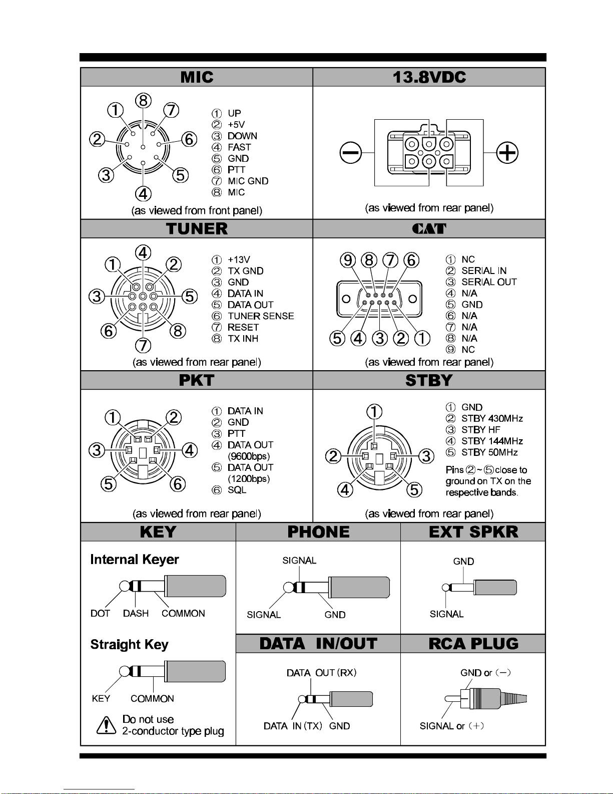
Plug Pinout ............................................................... 5
Installation................................................................ 6
Power Connections ................................................. 6
Grounding............................................................... 8
Base Station Earth Grounding .............................. 8
Mobile Station Grounding.................................... 9
AntennaConsiderations......................................... 10
Base Station Antenna Installations...................... 10
Mobile Antenna Installations.............................. 11
RF Field Exposure ................................................ 12
Electromagnetic Compatibility .............................. 12
Heat And Ventilation ............................................ 13
Base Station Wire Stand........................................ 13
Accessory Interfacing ............................................ 14
Linear Amplifier Interfacing............................... 14
VHF/UHF Preamplifiers .................................... 15
AFSK TNC Connections.................................... 16
FM Packet TNC Interfacing ............................... 17
CW Accessory Interfacing.................................. 18
Receiver Accessories ......................................... 18
Front Panel Controls & Switches........................... 20
Display Indicators and Icons.................................. 26
Rear Panel Connectors........................................... 28
Operation ............................................................... 30
Initial Setup .......................................................... 30
Operation Quick Start............................................ 31
Receiver Operation ............................................... 32
Frequency Navigation ........................................ 32
VFO Operation .................................................. 32
Main VFO Tuning Dial ...................................... 32
SUB-TUNE Knob.............................................. 32
Shuttle JogTM Ring ............................................. 33
MEM/VFO CH Knob......................................... 34
UP and DWN Scanning Keys (Microphone) ....... 34
qBANDpand qMHzpKeys......................... 35
Direct Frequency Entry via 12-key Keypad......... 35
Receiver Features .................................................. 36
RF Preamplifiers (Internal)................................. 36
RF Preamplifiers (External)................................ 36
Receiver Input Attenuator .................................. 36
AGC (Automatic Gain Control).......................... 36
RF Gain Control ................................................ 37
IF Noise Blanker ................................................ 37
Clarifier (Receiver Incremental Tuning) ............. 37
DSP Noise Reduction......................................... 38
Squelch (Receiver Muting)................................. 38
Voice Synthesizer .............................................. 38
Meterring........................................................... 39
Narrow IF Filters ............................................... 39
IF Shift .............................................................. 40
High Cut/Low Cut Controls (DSP) ..................... 40
Notch Filter (DSP) ............................................. 41
CW Reverse ...................................................... 41
Transmitting.......................................................... 43
SSB Transmission ................................................. 44
Basic Operation ................................................. 44
RF Speech Processor Operation ......................... 45
Voice Monitor ................................................... 45
SSB TX Frequency Response............................. 45
CW Transmittion .................................................. 46
Straigh Key/External Keying Device Operation .. 46
Electronic Keyer Operation ................................ 48
FM Transmission .................................................. 50
“Channelized” Frequency Navigation ................. 50
Simplex (non-repeater) Operation....................... 51
Repeater Operation ............................................ 52
DCS (Digital Coded Squelch) Operation ............ 54
DTMF (Autopatch) Operation ............................ 54
Cross-Band Repeater Operation ......................... 55
FM Packet Operation ............................................ 56
AFSK RTTY/Data Operation ................................ 57
AM Transmission .................................................. 58
Operation on Alaska Emergency Frequency.................
59
Antenna Tuner (FC-20) Operation ......................... 60
Active-Tuning Antenna System (ATAS-100) Operation ....
62
Split Trequency Operation (non-Satellite) .............. 64
Satellite Operation ................................................ 66
Satellite “Memory” Registers ............................. 68
Satellite Metering Options.................................. 68
Satellite Memory Labeling ................................. 69
Memory Operation................................................. 70
QMB (Quick Memory Bank) ................................. 70
Main Memory System ........................................... 71
Normal (“Simplex”) Memory Storage................. 71
Split-Frequency Memory Storage ....................... 72
Memory Cannel Recall....................................... 73
“Home” Channel Memory.................................. 74
Erasing Individual Memories.............................. 75
Erasing All Memories ........................................ 75
Smart SearchTM ....................................................... 76
Priority Channel Operation ................................... 77
ScanningOperation................................................ 78
Memory Channel “Skip” Feature........................ 79
Programmable Memory Scan ................................ 80
WeatherFax Monitoring ........................................ 81
Menu System .......................................................... 82
Activation of Menu System and Parameter Setting .82
Menu System Selection Chart ................................ 83
Menu Selection Details ......................................... 84
Satellite Memory Alpha-Numeric Tag Programming...
88
CAT
System Programming.................................. 91
Transceiver-to-Transceiver Cloning ...................... 94
Installation of Optional Accessories....................... 95
Optional Filters (YF-112S-02/YF-115C) ............... 95
Optional Voice Synthsizer Unit (FVS-1A) ............. 96
CPU Resetting & Memory Backup ........................ 97
In Case of Trouble ... .............................................. 98
Appendix .............................................................. 100
EME (Earth-Moon-Earth) Operation ................... 100
High-Speed CW Meteor Scatter Operation .......... 102
Table of Contents

1
FT-847 OPERATING MANUAL
The exciting new Yaesu FT-847 Earth Station is a revolutionary multimode transceiver providing coverage of all
nine HF Amateur bands, plus VHF/UHF coverage of the 50, 144, and 430 MHz bands.
The FT-847 Earth Station provides 100 Watts of power output on 160 through 6 meters, and 50 Watts output on
144 MHz and 430 MHz. General-coverage HF receive capability is provided, along with VHF/UHF reception at
37~76 MHz, 108~174 MHz, and 420~512 MHz. Independent antenna ports are provided: one each for HF, 50
MHz, 144 MHz, and 430 MHz.
The front panel’s multi-function blue display includes dual frequency registers, digital metering, and a wide vari-
ety of status displays. The FT-847’s compact size makes it ideal either for base station, field day, vacation, or VHF/
UHF “rover” expeditions.
Important features of the FT-847 Earth Station include: crossband full duplex capability with normal/inverted
tracking for satellite work; built-in low-noise preamplifiers; DSP Noise Reduction, Notch, and Bandpass Filters;
AFSK I/O port for teletype, HF packet, AMTOR, or high-speed CW work; 1200/9600 bps packet jack for VHF/
UHF; two tuning knobs plus Shuttle-Jog™ dial for easy frequency navigation; direct keyboard frequency entry;
Digital Speech Processor; adjustable CW pitch/sidetone; alpha-numeric label tags for labeling satellite memories;
built-in CW electronic keyer with weight control; built-in CTCSS/DCS encode-decode operation for FM; and a
high-speed (up to 57600 bps) CAT port for external computer control. Available options include Collins® Me-
chanical IF Filters for SSB and CW, and the FVS-1AVoice Synthesizer for visually impaired operators.
Thank you for your investment in the FT-847 Earth Station. We recommend that you read this manual in its
entirety as soon as possible, so as to gain a fuller understanding of the many capabilities of your new transceiver.
General Description
HF + V•UHF ALL MODE TRANSCEIVER
FT-847

2FT-847 OPERATING MANUAL
GENERAL
Frequency Range:Receive 100 kHz - 36.99 MHz
37 - 76 MHz
108 - 174 MHz
420 - 512 MHz
Transmit 160 - 6 Meters
2 Meters
70 Centimeters
(Amateur bands only)
5.1675 MHz (Alaska Emergency Channel)
Emission Modes:USB, LSB, CW, AM, FM, F1 (9600 bps Packet), F2 (1200 bps Packet), AFSK
Synthesizer Steps (Min.): 0.1 Hz (CW/SSB)
10 Hz (AM/FM)
Antenna Impedance:50Ω, Unbalanced
Operating Temp. Range:−10ºC to +50ºC (14ºF to 122ºF)
Frequency Stability:Better than ±2 ppm (0ºC to +40ºC) SSB/CW/AM/AFSK
Better than ±5 ppm (−10ºC to +50ºC) SSB/CW/AM/AFSK
Better than ±{1 kHz ±5 ppm} FM
Power Requirements:DC 13.8V —
---±10%, Negative Ground
Current Consumption:Receive (Squelched): 1.5A
Receive (Max. Audio): 2.0A
Transmit: 22A (@ 100W RF output)
Case Size:260(W) x 86(H) x 270(D) mm (10.24” x 3.39” x 10.63”)
Weight:Approximately 7 kg (14.4 lbs.)
TRANSMITTER
Power Output:160 - 6m: 100 Watts (25 Watts AM carrier)
2m/70cm: 50 Watts (12.5 Watts AM carrier)
Modulation Types:SSB: Balanced Modulator
FM: Variable Reactance
AM: Early Stage (Low Level)
FM Maximum Deviation:±5 kHz (±2.5 kHz on FM-N)
Spurious Radiation:Harmonics: At least 40 dB down (1.8 - 29.7 MHz)
At least 60 dB down (50/144/430 MHz)
Non-harmonic: At least 50 dB down (1.8 - 29.7 MHz)
At least 60 dB down (50/144/430 MHz)
Carrier Suppression:At least 40 dB
Opp. Sideband Suppression:At least 40 dB
3rd-Order IMD:At least 31 dB down (14 MHz, 100W PEP output)
SSB Frequency Response:400 Hz - 2600 Hz (−6 dB)
Microphone Impedance:200Ω- 10kΩ(Supplied microphone: 600Ω)
Specifications

3
FT-847 OPERATING MANUAL
RECEIVER
Sensitivity:SSB/CW AM-N FM
500 kHz - 1.8 MHz: −20 µV −
1.8 - 28 MHz: 0.25 µV 2 µV −
28 - 30 MHz: 0.25 µV 2 µV 0.5 µV
50 - 54 MHz: 0.20 µV 1 µV 0.25 µV
144/430 MHz: 0.125 µV −0.2 µV
(Above specifications are worst-case. SSB/CW/AM-N figures are for 10 dB S/N, 12 dB SINAD on FM)
Squelch Sensitivity:SSB/CW/AM FM
500 kHz - 1.8 MHz: 20 µV −
1.8 - 28 MHz: 2 µV −
28 - 30 MHz: 2 µV 0.25 µV
50 - 54 MHz: 1 µV 0.20 µV
144/430 MHz: 0.5 µV 0.16 µV
Image Rejection:Better than 60 dB
IF Rejection:Better than 60 dB
Selectivity (−6/−60 dB): SSB/CW: 2.2 kHz/4.5 kHz
CW-N: 0.5 kHz/2.0 kHz (Optional YF-115C installed)
AM: 9 kHz/20 kHz
AM-N: 2.2 kHz/4.5 kHz
FM: 15 kHz /30 kHz
FM-N: 9 kHz/20 kHz
Audio Output:At least 1.5W into 8Ω@ 10% THD
Audio output impedance:4Ω- 16Ω
Specifications are subject to change, in the interest of improvement, without notice or obligation.
Specifications are guaranteed only within Amateur bands.
Specifications

4FT-847 OPERATING MANUAL
Accessories & Options
SUPPLIED ACCESSORIES
Item Quantity
MH-31B8 Hand Microphone .............................................................................................................................1
DC Cable fused for 25 Amps (T9019925) .........................................................................................................1
Spare 25 Amp Fuse (Q0000074) .......................................................................................................................1
AVAILABLE OPTIONS
MH-36D8 DTMF Microphone
MD-100A8X Desk-Top Microphone
YF-115S-02 SSB Filter (Collins® Mechanical Filter)
YF-115C CW Filter (Collins® Mechanical Filter)
FC-20 Automatic Antenna Tuner
ATAS-100 Active-Tuning Antenna System
FVS-1A Voice Synthesizer Unit
MMB-66 Mobile Mounting Bracket
FP-1030A AC Power Supply, Linear Type (25A)
FP-1023 AC Power Supply, Switching Regulator Type (23A) (U.S.A. only)
CT-39 Packet Cable
CT-61 STBY Cable
RCA Connector (P/N P0090544)
5-pin Mini DIN Plug (P/N P0090976)
3-pin Phone Plug (P/N P0090008)
2-pin Miniature Plug (P/N P0090034)

5
FT-847 OPERATING MANUAL
Plug Pinout

6FT-847 OPERATING MANUAL
POWER CONNECTIONS
Installation
The DC power connector for the FT-847 must only be
connected to a DC source providing 13.8 Volts DC
(±10%), and capable of at least 22 Amperes of cur-
rent. Always observe proper polarity when making DC
connections:
The RED DC power lead connects to the POSITIVE
(+) DC terminal; and
The BLACK DC power lead connects to the NEGA-
TIVE (-) DC terminal.
For base station installations, Yaesu recommends the
use of the FP-1025 or FP-1030A AC power supplies.
Other models of power supplies may be used with the
FT-847, but the 13.8V DC input voltage, 22-Ampere
current capability, and DC cable polarity guidelines
described above must be strictly followed.
Note that other manufacturers may use the same type
of DC power connections as does your FT-847 trans-
ceiver, but the wiring configuration of the other
manufacturer’s plug may be different from that speci-
fied for your transceiver. Serious damage can be caused
if improper DC connections are made; consult with a
qualified service technician when in doubt.
In mobile installations, noise pickup may be minimized
by connecting the DC cable directly to your vehicle’s
battery, rather than to the ignition switch or “acces-
sory” circuitry. Direct connection to the battery also
provides the best voltage stability.

7
FT-847 OPERATING MANUAL
Tips for Successful
Mobile Installations:
rBefore connecting the DC cable to the battery, mea-
sure the voltage across the battery terminals with
the engine running fast enough to show a charge. If
the voltage is above 15 Volts, the vehicle’s voltage
regulator should be adjusted to reduce the charg-
ing voltage to 14 Volts or lower.
rRoute the DC cable as far away from the ignition
cables as possible, and cut off any excess cable
(from the battery end) to minimize voltage drop.
rIf the DC cable is not long enough, use #12 AWG
(minimum) stranded, insulated wire to extend it.
Be certain to solder the connections at the splice
securely, and provide ample insulation for the sol-
dered splice (heat shrink tubing plus black electri-
cal tape work well).
rBe sure that the POWER switch on the FT-847 is
OFF when connecting the DC cable’s connector
to the rear panel 13.8VDC jack.
rBe sure that the POWER switch on the FT-847 is
OFF when starting your car. There initially may
be no voltage regulation, which may cause erratic
operation of your transceiver’s microprocessor.
rCheck the battery terminal connections frequently
to be sure they are tight and not corroded.
Installation
POWER CONNECTIONS
Caution
Permanent damage can result if improper sup-
ply voltage, or reverse-polarity voltage, is ap-
plied to the FT-847. The Limited Warranty on
this transceiver does not cover damage caused
by application of AC voltage, reversed polarity
DC, or DC voltage outside the specified range
of 13.8V ±10%.
When replacing fuses, be certain to use a fuse
of the proper rating. The FT-847 requires a 25A
fast-blow fuse.

8FT-847 OPERATING MANUAL
GROUNDING
The provision of an effective ground system is impor-
tant in any successful communications station. A good
ground system can contribute to station efficiency in a
number of ways:
rIt can minimize the possibility of electrical shock
to the operator.
rIt can minimize RF currents flowing on the shield
of the coaxial cable and the chassis of the trans-
ceiver which may cause interference to nearby
home entertainment devices or laboratory test
equipment.
rIt can minimize the possibility of erratic transceiver
operation caused by RF feedback or improper cur-
rent flow through logic devices.
An effective earth ground system may take several
forms; for a more complete discussion, see an appro-
priate RF engineering text. The information presented
below is intended only as a guideline.
Base Station Earth
Grounding
Typically, the ground connection consists of one or
more copper-clad steel rods, driven into the ground. If
multiple ground rods are used, they should be config-
ured in a “V” configuration, and bonded together at
the apex of the V which is nearest the station location.
Use a heavy, braided cable (such as the discarded shield
from type RG-213 coaxial cable) and strong cable
clamps to secure the braided cables to the ground rods.
Be sure to weatherproof the connections to ensure
many years of reliable service. Use the same type of
heavy, braided cable for the connections to the station
ground bus (described below).
Do not use gas line pipes in an attempt to provide a
ground connection! To do so creates a serious risk of
explosion!!
Inside the station, a common ground bus consisting of
a copper pipe of at least 25 mm (1”) diameter should
be used. An alternative station ground bus may con-
sist of a wide copper plate (single-sided circuit board
material is ideal) secured to the bottom of the operat-
ing desk. Grounding connections from individual de-
vices such as transceivers, power supplies, and data
communications devices should be made directly to
the ground bus using a heavy, braided cable.
Do not make ground connections from one electrical
device to another, and thence to the ground bus. This
so-called “Daisy Chain” grounding technique may
nullify any attempt at effective radio frequency ground-
ing. See the drawings below for examples of proper
and improper ground connections.
Inspect the ground system −inside the station as well
as outside −on a regular basis so as to ensure maxi-
mum performance and safety.
Installation

9
FT-847 OPERATING MANUAL
Installation
GROUNDING
Mobile Station Grounding
Although satisfactory grounding in most installations
will be achieved via the DC cable’s negative lead and
the antenna system’s coaxial cable shield, it is often
recommended that you provide a direct ground con-
nection to the vehicle chassis at the mounting loca-
tion of the transceiver. Due to unexpected resonances
which may naturally occur in any location, improper
communication system performance may result from
insufficient grounding. These symptoms may include:
lRF feedback (resulting in distortion of your
transmitted signal);
lUnintended frequency change;
lBlinking or blanking of the frequency display;
lNoise pickup; and/or
lLoss of memory.
Note that these conditions may occur in any commu-
nications installation. The FT-847 includes extensive
filtering designed to minimize the chance of such prob-
lems; however, random currents set up by insufficient
RF grounding can nullify such filtering. Bonding the
rear panel Ground lug of the FT-847 transceiver to the
vehicle or vessel’s ground system should clear up any
such difficulties.
Yaesu does not recommend the use of “on glass” mo-
bile antennas unless the shield of the coaxial cable is
securely grounded near the feedpoint of the antenna.
Such antennas frequently are responsible for the
ground-related difficulties described above.

10 FT-847 OPERATING MANUAL
ANTENNA CONSIDERATIONS
Installation
The antenna systems connected to your FT-847 trans-
ceiver are, of course, critically important in ensuring
successful communications. The FT-847 is designed
for use with any antenna system providing a 50Ωre-
sistive impedance at the desired operating frequency.
While minor excursions from the 50Ωspecification
are of no consequence, the power amplifier’s protec-
tion circuitry will begin to reduce the power output of
there is more than a 50% divergence from the speci-
fied impedance (less than 33Ωor greater than 75Ω,
corresponding to a Standing Wave Ratio (SWR) of
1.5:1).
Four antenna jacks are provided on the rear panel of
the FT-847, using two different types of connectors.
Three of these jacks are “Type M” (SO-239) jacks;
these are the HF, 50 MHz, and 144 MHz jacks. The
other jack is a “Type N” jack, which is the 430 MHz
jack.
The center pins of these two jack types are of very
different diameters, and damage (not covered by your
transceiver’s Limited Warranty) will be caused if you
attempt to connect a Type M (PL-259) plug to the 430
MHz Type N jack. It is best to confirm visually that
you are connecting your coaxial cables to the correct
jacks.
Guidelines for successful base and mobile station in-
stallations are shown below.
Base Station Antenna
Installations
When installing a “balanced” antenna such as a Yagi
or dipole, remember that the FT-847 is designed for
use with an (unbalanced) coaxial feedline. Always
use a balun or other balancing device so as to ensure
proper antenna system performance.
Use high-quality 50Ωcoaxial cable for the lead-in to
your FT-847 transceiver. All efforts at providing an
efficient antenna system will be wasted if poor qual-
ity, lossy coaxial cable is used. Losses in coaxial lines
increase as the frequency increases, so a coaxial line
with 0.5 dB of loss at 7 MHz may have 6 dB of loss at
432 MHz (thereby consuming 75% of your
transceiver’s power output!). As a general rule, smaller-
diameter coaxial cables tend to have higher losses than
larger-diameter cables, although the precise differences
depend on the cable construction, materials, and the
quality of the connectors used with the cable. See the
cable manufacturers’ specifications for details.
For reference, the chart below shows approximate loss
figures for typically-available coaxial cables frequently
used in HF installations.
CABLE TYPE LOSS
1.8 MHz 28 MHz 432 MHz
RG-58A 0.55 2.60 >10
RG-58 Foam 0.54 2.00 8.0
RG-8X 0.39 1.85 7.0
RG-8A, RG-213 0.27 1.25 5.9
RG-8 Foam 0.22 0.88 3.7
Belden 9913 0.18 0.69 2.9
7/8" "Hardline" <0.1 0.25 1.3
Loss in dB per 30m (100 feet)
for Selected 50
Ω
Coaxial Cables
(Assumes 50ΩInput/Output Terminations)
Loss figures are approximate;
consult cable manufacturers'
catalogs for complete specifica-
tions.

11
FT-847 OPERATING MANUAL
Installation
Always locate antennas such that they can never come
in contact with outdoor power lines in the event of a
catastrophic support or power-pole structural failure.
Ground your antennas’ support structure(s) adequately,
so as to dissipate energy absorbed during a lightning
strike. Install appropriate lightning arrestors in the
antenna coaxial cables (and rotator cables, if rotary
antennas are used).
In the event of an approaching electrical storm, dis-
connect all antenna lead-in, rotator cables, and power
cables completely from your station if the storm is
not immediately in your area. Do not allow discon-
nected cables to touch the case of your FT-847 trans-
ceiver or accessories, as lightning can easily jump from
the cable to the circuitry of your transceiver via the
case, causing irreparable damage. If a lightning storm
is in progress in your immediate area, do not attempt
to disconnect the cables, as you could be killed in-
stantly if lightning should strike your antenna struc-
ture or a nearby power line.
If a vertical antenna is utilized, be certain that humans
and/or pets and farm animals are kept away both from
the radiating element (to prevent electrical shock and
RF exposure danger) and the ground system (in the
event of an electrical storm). The buried radials of a
ground-mounted vertical antenna can carry lethal volt-
ages outward from the center of the antenna in the
event of a direct lightning strike.
ANTENNA CONSIDERATIONS
Mobile Antenna Installations
Mobile antennas for the HF bands, with the possible
exception of those designed for 28 MHz, display very
high “Q” due to the fact that they must be physically
shortened, then resonated using a loading coil. Addi-
tional system bandwidth may be realized using the
Yaesu FC-20 Automatic Antenna Tuner, which will
present a 50Ωimpedance to your transceiver on the
1.8 ~ 50 MHz bands so long as the SWR on the co-
axial line connected to the FC-20 is below 3:1.
On the VHF and UHF bands, coaxial line
losses increase so rapidly in the presence of
SWR that we recommend that all antenna
matching to 50Ωbe performed at the antenna
feedpoint.
Yaesu’s Active-Tuned Antenna System
(ATAS-100) is a unique HF/VHF/UHF mo-
bile antenna system, which provides auto-
matic tuning when used with the FT-847. See
page 62 for full details on the ATAS-100.
For VHF/UHF weak-signal (CW/SSB) op-
eration, remember that the antenna polariza-
tion standard for these modes is horizontal,
not vertical, so you must use a loop or other-
wise horizontally-polarized antenna so as to
avoid cross-polarization loss of signal
strength (which can be 20 dB or more!). On
HF, signals propagated via the ionosphere
develop mixed polarizations, so antenna se-
lection may be made strictly on mechanical
considerations; vertical antennas are almost
always utilized on HF for this reason.
Photo
Horizontal Loop
for SSB/CW Operation

12 FT-847 OPERATING MANUAL
RF FIELD EXPOSURE
This transceiver is capable of power output in excess
of 50 Watts, so customers in the United States may be
required to demonstrate compliance with Federal Com-
munications Commission (FCC) regulations concern-
ing maximum permissible exposure to radio frequency
energy. Compliance is based on the actual power out-
put used, feedline loss, antenna type and height, and
other factors which can only be evaluated as a system.
Information regarding these regulations may be avail-
able from your Dealer, your local radio club, from the
FCC directly (press releases and other information can
be found on the FCC’s site on the World Wide Web at
<http://www.fcc.gov>), or from the American Radio
Relay League, Inc. (225 Main St., Newington CT
06111 or <http://www.arrl.org>).
Although there is negligible radio frequency (RF) leak-
age from the FT-847 transceiver itself, its antenna sys-
tem should be located as far away from humans and
animals as practicable, so as to avoid the possibility of
shock due to accidental contact with the antenna or
excessive long-term exposure to RF energy. During
mobile operation, do not transmit if someone is stand-
ing adjacent to your antenna, and use the lowest power
possible.
Never stand in front of an antenna (during testing or
operation) when RF power is applied, especially in
the case of 430 MHz directional arrays. The 50 Watt
power output supplied by the FT-847, combined with
the directivity of a beam antenna, can cause immedi-
ate heating of human or animal tissues, and may cause
other undesirable medical effects.
Installation
ELECTROMAGNETIC COMPATIBILITY
If this transceiver is used with, or in the vicinity of, a
computer or computer-driven accessories, you may
need to experiment with grounding and/or Radio Fre-
quency Interference (RFI) suppression devices (such
as ferrite cores) to minimize interference to your com-
munications caused by energy from the computer.
Computer-generated RFI is usually a result of inad-
equate shielding of the computer’s cabinet or I/O and
peripheral connections. While computer equipment
may “comply” with RF emission standards, this does
not ensure that sensitive amateur radio receivers like
the FT-847 will not experience interference from the
device!
Be certain to use only shielded cables for TNC-to-
Transceiver connections. You may need to install AC
line filters on the power cord(s) of the suspected equip-
ment, and decoupling ferrite toroidal chokes may be
required on interconnecting patch/data cables. As a
last resort, you can try installing additional shielding
within the computer’s case, using appropriate conduc-
tive mesh or conductive shielding tape. Especially
check “RF holes” where plastic is used for cabinet front
panels.
For further information, consult amateur radio refer-
ence guides and publications relating to RFI suppres-
sion techniques.

13
FT-847 OPERATING MANUAL
Installation
HEATAND VENTILATION
To ensure long life of the components, be certain to
provide adequate ventilation around the cabinet of the
FT-847. The cooling system of the transceiver must
be free to draw cool air in from the side of the trans-
ceiver and expel warm air from the rear of the trans-
ceiver.
Do not install the transceiver on top of another heat-
generating device (such as a linear amplifier), and do
not place equipment, books, or papers on top of the
transceiver. Place the transceiver on a hard, flat, stable
surface. Avoid heating vents and window locations that
could expose the transceiver to excessive direct sun-
light, especially in hot climates.
BASE STATION WIRE STAND
The heavy wire stand on the bottom of the transceiver
allows the transceiver to be tilted upward for better
viewing. Simply fold the stand forward to raise the
front of the transceiver, and fold it back against the
bottom case to lower the front of the FT-847.
Note:Do not use the wire stand as a carrying handle,
as it could slip out of its mount, causing the trans-
ceiver to be dropped! Use the carrying handle on the
side of the FT-847 for transport purposes.

14 FT-847 OPERATING MANUAL
ACCESSORYINTERFACING
Installation
The FT-847 may be connected to a wide variety of
accessories in your amateur station. Wherever possible
(e.g. PTT, ALC, KEY, SPKR, PKT, DATA, CAT,
ANTENNA) commonly-accepted standard connectors
have been used for accessory interfacing so as to mini-
mize the need for “custom” cabling.
Linear Amplifier Interfacing
The FT-847 provides the switching and control lines
required for easy interfacing to most all commonly-
available amplifiers used today.
These include:
lSeparate RF output jacks for HF, 50 MHz, 144
MHz, and 430 MHz;
lSeparate T/R control lines (open-circuit on RX,
closure to ground on TX); and
lA negative-going ALC jack (control voltage
range: 0 to −4V DC).
The T/R control lines are transistor “open collector”
circuits, capable of handling positive amplifier relay
coil voltage of up to +24V DC and current of up to
100 mA.
Important Note!
Do not exceed the maximum voltage or current
ratings for the STBY jack. This jack is not com-
patible with negative DC voltages, nor AC volt-
ages of any magnitude.
Most amplifier control relay coils require much
lower voltage/current switching capability (typi-
cally, +12V DC at 25-75 mA), and the switch-
ing transistors in the FT-847 will easily accom-
modate such amplifiers.
Typical amplifier interface circuits are shown below.
Note that some amplifiers, particularly VHF or UHF
“brick” amplifiers, offer two methods of T/R switch-
ing: application of +13V or a closure to ground. Be
sure to configure your amplifier so that it switches via
a closure to ground, as provided by your FT-847.
STBY Cable
ALC Cable

15
FT-847 OPERATING MANUAL
Installation
VHF/UHF Preamplifiers
For maximum improvement of system noise figure,
VHF and (especially) UHF preamplifiers should be
located as close to the antenna feedpoint as possible.
This puts the preamplifier’s low-noise-figure gain
ahead of the loss in the coaxial cable feedline.
The FT-847 provides the capability to deliver +12V
DC at up to 300 mA via the 144 MHz and/or 430 MHz
antenna jacks, for those preamplifiers equipped to re-
ceive DC power via the coaxial cable. Menu items #29
and #30 provide the following operational settings:
lIn the “
INT
” mode, the internal preamplifier of
the FT-847 is used, and no DC power is deliv-
ered to the rear panel antenna jack(s).
lIn the “
ANT
” mode, the internal preamplifier is
bypassed, and +12V DC is delivered to the an-
tenna jack(s).
Menu #29 controls the setting for the 144 MHz an-
tenna jack, while Menu #30 controls the setting for
the 430 MHz antenna jack. These settings are totally
independent, so each antenna port may be set for the
configuration you desire on that particular band.
If you wish to use both the internal preamplifier and a
very-low-noise tower-mounted preamp, set Menu #29
and/or #30 to “
INT
” and supply DC power to your
preamp(s) via a separate DC cable.
ACCESSORYINTERFACING
Caution!
Check your antenna system switching carefully
before activating the “
ANT
” setting of Menu #29
or #30. If there are any antennas in your system
which present a DC Ground when checked with
an Ohmmeter, you should be certain that there
is no way that such an antenna can be connected
directly to the FT-847 (without the intervening
preamplifier). Direct connection of a DC short
to ground will instantly destroy the transistor
passing the +12V DC to the antenna jack.
This trouble may be avoided by putting your
antenna switch(es) in a remote position on the
antenna side of the preamplifier, so that all an-
tennas are isolated from the FT-847 by the
preamp(s).
The Limited Warranty for the FT-847 does not
cover damage caused by improper installation.
Check your antennas before connecting them
to be sure!
Note: the default selection for both Menu #29
and #30 is set to “
INT
” at the factory to avoid
accidental damage to your transceiver.

16 FT-847 OPERATING MANUAL
AFSK TNC Connections
(for HF RTTY and Packet, etc.)
The FT-847 is easy to connect to most all Terminal
Node Controllers (TNCs) or other digital modem units
used for RTTY, HF Packet, and other digital modes
utilizing either USB or LSB.
Audio Frequency-Shifted Keying (AFSK) operation
for HF Baudot, AMTOR, 300 bps Packet, etc. is pro-
vided via the rear-panel DATA IN/OUT terminal.
The tip connector of this jack accepts “TX Audio”
from the TNC; the optimum level is 20 mV at 10 kΩ
impedance. The ring connector provides “RX Audio”
from the FT-847’s receiver. This is fixed-level audio
200 mV at 10 kΩ, not affected by the setting of the
front panel’s AF control.
The other connection required for AFSK operation is
PTT control of the transceiver’s transmit/receive sta-
tus. Use the illustration below to connect the TNC’s
PTT line to the DATA IN/OUT terminal.
Note:If you use the rear-panel’s “PTT” jack for AFSK
operation, the transceiver will operate in the “SSB”
mode, with the microphone connected. Activating PTT
via the DATA IN/OUT jack disconnects the micro-
phone.
Installation
ACCESSORYINTERFACING
Caution!
Some digital modes, such as RTTY (Radio
TeleType), require continuous key-down trans-
mission. While the internal fan is designed to
protect your transceiver from excessive heat, full
key-down output for long periods is not recom-
mended. Especially during hot or humid
weather, we recommend minimizing continuous
full-power transmit time to ensure long life of
the transceiver components, with a three-minute
maximum being recommended (with a five
minute “rest” period thereafter).
If possible, adjust the transmit audio input level
to restrict the power output to 50 Watts or less
on HF, 25 Watts or less on 144/430 MHz, if
longer transmissions (and/or shorter “rest” pe-
riods) are required.
Typical connection information is presented below.

17
FT-847 OPERATING MANUAL
Installation
ACCESSORYINTERFACING
FM Packet TNC Interfacing
The FT-847 provides a convenient rear-panel PKT jack
for easy connections to your TNC. The connections to
this jack are in accordance with a standard adopted by
many amateur-product manufacturers. However, we
recommend that you verify the connections to any cable
you already own by comparison to the pictorial be-
low.
Only the “Main” band may be used for packet opera-
tion, as there are no connections to the “Sub” band via
the PKT jack.
The FT-847’s PKT jack connections are optimized for
the data transmission and reception speed in use. In
accordance with industry standards, the signal levels,
impedances, and bandwidths are significantly differ-
ent on 9600 bps as opposed to 1200 bps. If your TNC
does not provide multiple lines to accommodate such
optimization, you may still be able to utilize your TNC,
if it is designed for multiple-radio use, by connecting
the TNC “Radio 1” port to the 1200 bps lines on the
FT-847, and the “Radio 2” port to the 9600 bps lines.
For ease in making connections to your TNC, the op-
tional CT-39 Packet Cable for the FT-847 is available
from your Yaesu dealer. With reference to the “PKT
Jack Pin Connections” chart and data jack pinout
pictorial on this page, you may connect your TNC in
minutes using the color code information provided.
Most modern TNCs use a PLL-type DCD (Data Car-
rier Detect) circuit, so you will generally not need to
connect anything to the Squelch Control line (Pin 6)
of the PKT jack.
Note that 9600 bps packet transmit-deviation adjust-
ment is very critical to successful operation, and can
only be accomplished using a calibrated deviation
meter (such as that found on an FM Service Monitor
used in a communications service center). In most
cases, the Packet Data Input level (set via a potenti-
ometer inside the TNC) must be adjusted to provide a
deviation of ±2.75 kHz (±0.25 kHz). Check with your
packet node’s sysop if you have any questions about
the appropriate deviation level for your network.
The setting of the 1200 bps Packet Data Input level is
much less critical, and satisfactory adjustment to the
optimum (±2.5 ~ ±3.5 kHz) deviation can usually be
done “by ear” by adjusting the TNC’s 1200 bps TX
Audio Level potentiometer so that the outgoing pack-
ets (as monitored on a separate VHF or UHF receiver)
are slightly lower than the level of your speech. If you
have the optional MH-36D8 DTMF Microphone, set
your TNC’s tone output to be about the same level as
that of the DTMF tones produced by the MH-36D8.
The “RX 1200” and “RX 9600” lines are fixed-level
audio outputs, not affected by the setting of the AF
(GAIN)control. Selection of the Packet Baud Rate to
be used is performed via Menu #23. See the section
on “FM PACKET OPERATION” on page 56 for details.
PKT Jack Pin Connections
Pin Label Notes
1PKD
Packet Data Input
Impedance: 10 kΩ
Max. Input Level:
40 mV pp @ 1200bps
2.0 V pp @ 9600bps
2GND Signal Ground
3PTT Ground on Transmit
4RX9600 9600bps Packet Data Out
Impedance: 10 kΩ
Max. Output Level: 500 mV pp
5RX1200 1200bps Packet Data Out
Impedance: 10 kΩ
Max. Output Level: 300 mV pp
6SQL Squelch Control
Squelch Open: +5V
Squelch Closed: 0V

18 FT-847 OPERATING MANUAL
CW Accessory Interfacing
All commonly-available keyer paddles should work
perfectly with the built-in Electronic Keyer. The wir-
ing configuration for the paddle is shown below.
For straight-key operation, only the tip and shaft con-
nections are used.
Note:Even when using a straight key, you must use a
three-conductor (“stereo”) plug. If a two-con-
ductor plug is used, the key line will be con-
stantly shorted to ground.
When using an external electronic keyer, be absolutely
certain that it is configured for “positive” keying, not
“negative” or “grid block” keying. The “key-up” volt-
age of the FT-847 is +5V, and the “key-down” current
is only about 2 mA.
For CW automated keying using a personal computer,
with an external memory keyer providing for manual
sending, it usually is possible to connect the keyed
lines together via a “Y” connector, as shown below.
Check with the documentation accompanying your
keyer and your contest/DX software for any cautions
which need to be observed.
Installation
ACCESSORYINTERFACING
Receiver Accessories
(TAPE RECORDER, WEATHERFAX DEMODULATOR, etc.)
For weak-signal VHF work, including meteor scatter
and EME (Moonbounce), it often is desirable to record
your contacts for future reference. During high-speed
CW meteor-scatter schedules, tape recording (or feed
of RX Audio to a computer) is required for decoding
of the incoming signal bursts.
Connection of a tape recorder, WeatherFax demodu-
lator, or other receiver accessory is easily accomplished
using the DATA IN/OUT jack’s Ring connector, as
shown in the illustration below. The audio output level
is fixed at 20 mV with an impedance of 10 kΩ.
Other manuals for FT-847
4
Table of contents
Other Yaesu Transceiver manuals

Yaesu
Yaesu FT3DR User manual

Yaesu
Yaesu FT-450D User manual

Yaesu
Yaesu CT-39A User manual

Yaesu
Yaesu FT-225RD User manual

Yaesu
Yaesu FTM-6000R User manual

Yaesu
Yaesu FT-One User manual

Yaesu
Yaesu FT-60 HT User manual

Yaesu
Yaesu FTM-400DR User manual

Yaesu
Yaesu FT-767GX User manual

Yaesu
Yaesu FT DX 3000 User manual