(7) When the loading process is complete, an [OK?] box will appear. Click [OK?].
(8) Turn off the main power switch, (or turn off the power supply for FT-2000D and wait a minute,
until the capacitors discharge) and unplug the AC power cord.
(9) Unplug the CT-119 from the radio.
(10) Plug the AC power cord into the radio and turn the main power switch on the back of the radio
to the ON position (or turn on the power supply for FT-2000D).
(11) Plug the radio back in. Press and hold in the [FAST] and [LOCK] keys; while holding them in,
press the front power switch to turn the radio on. This resets the radio and locks in the new
software.
(12) Turn the radio off. The main CPU updating process is now complete. Follow the instructions
below to update the EDSP.
EDSP
EDSP Software Update
This procedure is used for uploading new EDSP Software into the FT-2000/D Amateur Transceivers,
from your personal computer, using the RS-232C, DB9F to DB9F straight cable.
1. Turn off the main power switch located on the back of the FT-2000 (or turn off the power supply
for FT-2000D and wait a minute, until the capacitors discharge) and remove the AC power cord.
2. Connect a serial RS-232C, DB9F to DB9F straight cable to the COM1 connector of your
computer and the 9-pin CAT connector on the rear of the transceiver. If you use a USB to serial
adapter, you might need to change the COM Port number.
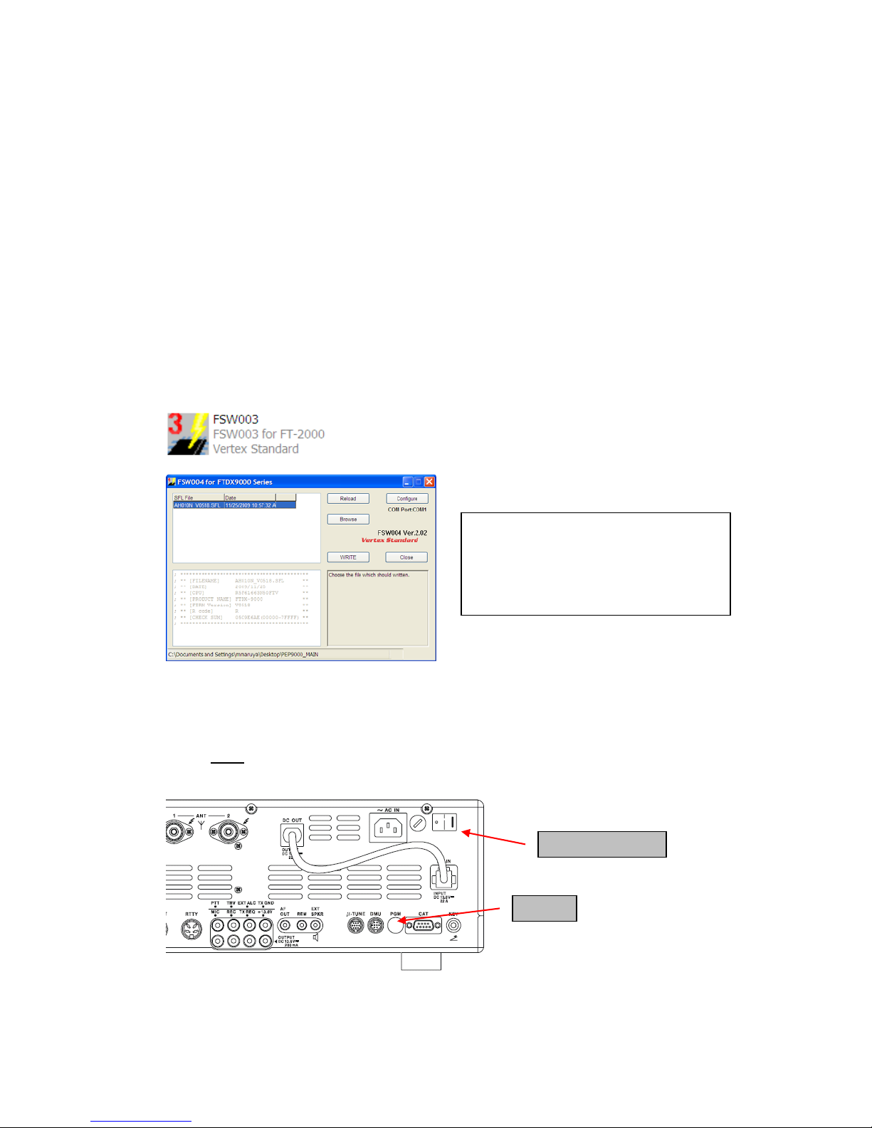
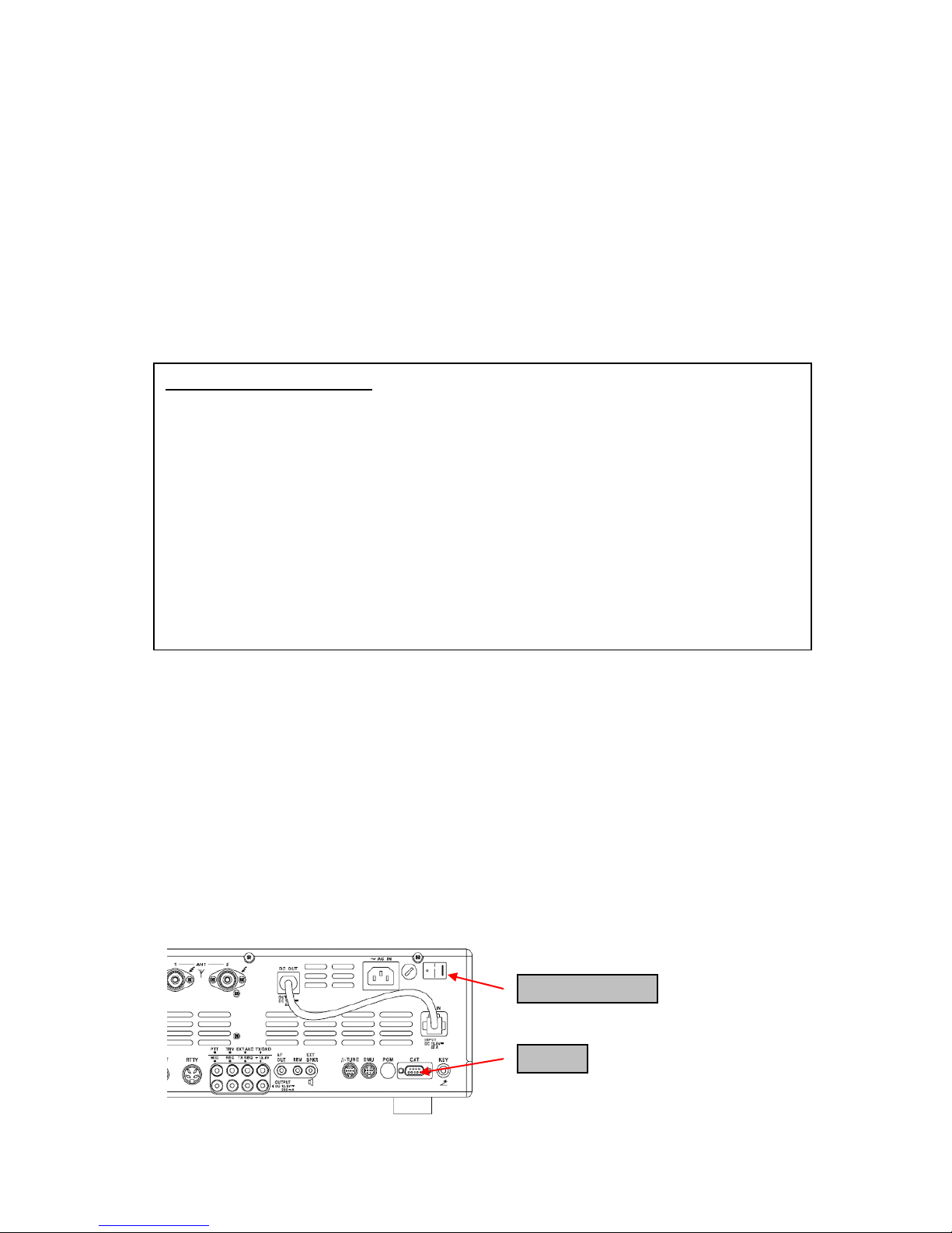
CAT
Main Power SW
8-pin mini-DIN PGM-SW
1. Turn the main REAR power switch OFF.
2. Connect a RS-232C straight cable to the CAT connector.
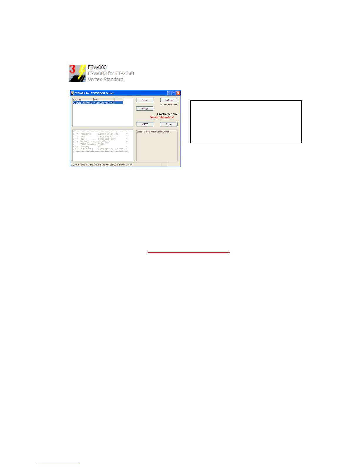
3. Open the file FSW003.
4. Insert the 8-pin mini-DIN PMG-SW connector to FT-2000/D (PMG) jack.
5. Turn on the REAR Main power switch.
6. I choose the .sfl file of the version V0150 to write in and push WRITE of the screen.
7. When complete appears, click OK. Turn the REAR power switch OFF.
8. Remove the 8-pin mini-DIN PMG-SW and the RS-232C cable.
9. Turn on REAR power switch.
10. Reset the radio to default.
NOTE: for a more detailed description see the Main CPU programming.