Yamabiko ECHO PB-2520 User manual

Ref. No. 403-20
(Serial number: 37000001 and after)
Copyright(C)2018 YAMABIKO Corporation All rights reserved.
PB-2520
ECHO:
shindaiwa:
EB252

INTRODUCTION
This service manual contains information for
service and maintenance of ECHO HANDHELD
BLOWER, model PB-2520 and shindaiwa
HANDHELD BLOWER, model EB252.
For systematic diagnosis, to avoid extra work,
time loss and to meet Emission regulation,
please refer to “Troubleshooting guide” that
describes problems, testing, remedies and
references. We recommend you make use of
Operator’s Manual and Parts Catalogue together
with this manual when servicing.
We are constantly working on technical improve-
ment of our products. For this reason, technical
data, equipment and design are subject to
change without notice. All speci¿cations, illustra-
tions and directions in this manual are based on
the latest product information available at the
time of publication.

TABLE OF CONTENTS
PB-2520
EB252 1
Page Page
1 SERVICE INFORMATION.....................................2
1-1 Speci¿cations...................................................2
1-2 Technical data ..................................................3
1-3 Torque limits.....................................................4
1-4 Special repairing materials...............................4
1-5 Service limits....................................................5
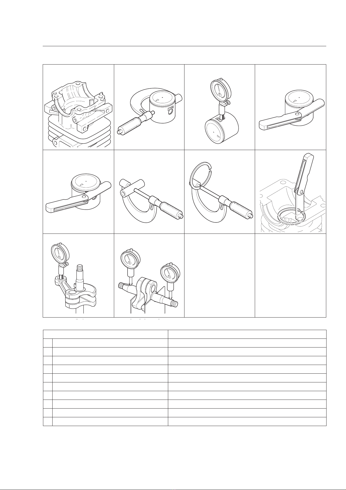
1-6 Special tools.....................................................6
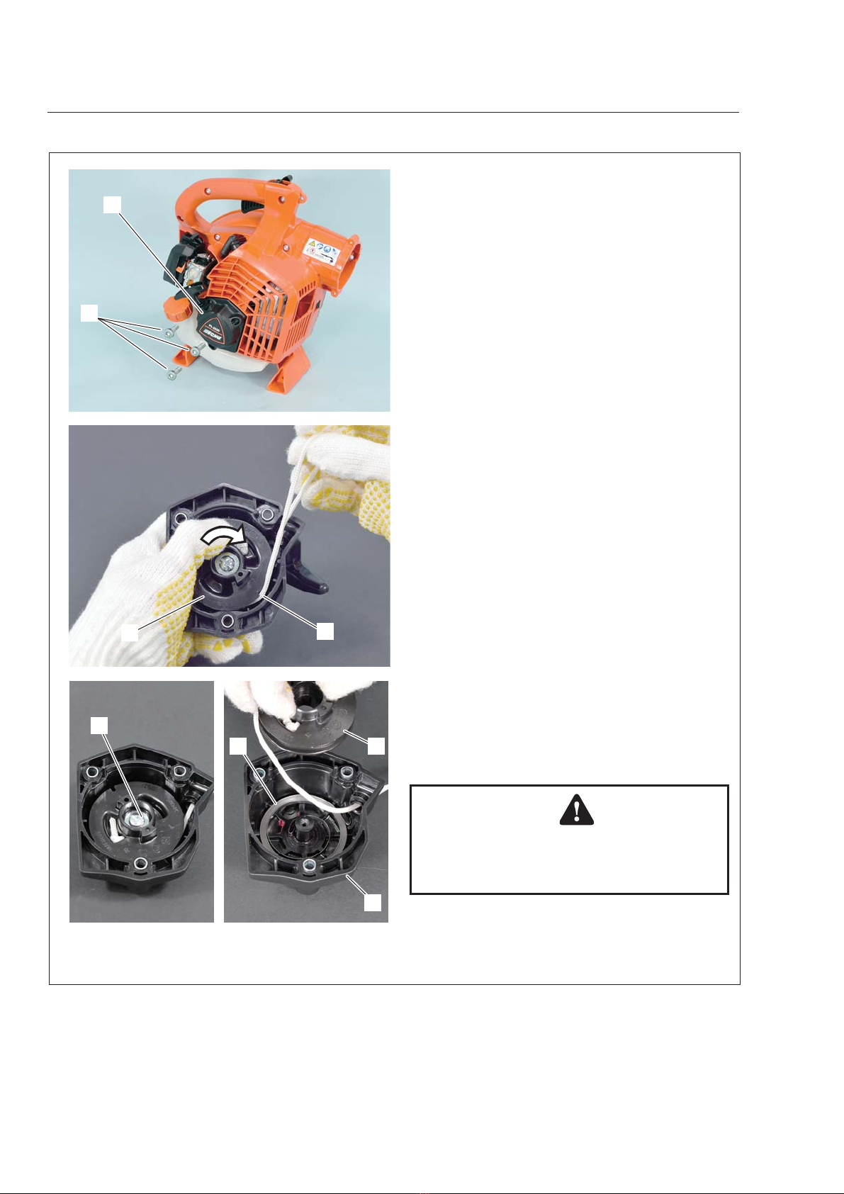
2 STARTER SYSTEM ..............................................7
2-1 Disassembling starter assembly.......................8
2-2 Replacing starter rope......................................9
2-3 Installing rewind spring...................................10
2-4 Assembling starter..........................................11
2-5 Replacing starter pawl....................................12
3 BLOWER SYSTEM.............................................13
3-1 Inspecting fan and fan case ...........................14
3-2 Disassembling and assembling
fan and fan case.............................................14
4 IGNITION SYSTEM.............................................17
4-1 Troubleshooting guide....................................18
4-2 Testing spark..................................................19
4-3 Inspecting spark plug .....................................19
4-4 Replacing spark plug cap and coil..................20
4-5 Inspecting ignition module..............................21
4-6 Replacing ignition module..............................22
4-7 Setting pole shoe air gaps..............................24
4-8 Inspecting ignition switch................................24
4-9 Replacing ignition switch................................25
4-10 Inspecting Àywheel magnetic force ................26
4-11 Replacing Àywheel and key............................26
5 HANDLE AND CONTROL SYSTEM ..................28
5-1 Disassembling and assembling
handle and control parts.................................29
6 FUEL SYSTEM ...................................................30
6-1 Inspecting air ¿lter..........................................31
6-2 Inspecting fuel cap and fuel strainer...............31
6-3 Inspecting fuel tank and line...........................32
6-4 Inspecting and replacing tank vent.................33
6-5 Replacing fuel line, fuel return line,
tank vent line and grommet............................35
6-6 Adjusting carburetor.......................................36
6-6-1 General adjusting rules ..................................36
6-6-2 Initial setting Throttle adjust screw,
L mixture needle and H mixture needle..........37
6-6-3 Adjusting carburetor.......................................37
6-6-4 Inserting limiter plugs .....................................38
6-7 Testing carburetor...........................................39
6-8 Inspecting crankcase pulse passage .............40
6-9 Inspecting metering lever height ....................40
6-10 Inspecting inlet needle valve..........................41
6-11 Inspecting diaphragm.....................................41
6-12 Installing carburetor........................................42
7 ENGINE...............................................................43
7-1 Testing cylinder compression.........................44
7-2 Cleaning cooling air passages .......................44
7-3 Inspecting mufÀer and exhaust port...............45
7-4 Testing crankcase and cylinder sealings........46
7-5 Replacing oil seal...........................................47
7-6 Inspecting cylinder..........................................47
7-7 Inspecting piston and piston ring....................48
7-8 Disassembling crankcase...............................48
7-9 Replacing ball bearings..................................49
7-10 Assembling crankshaft and crankcase...........50
7-11 Installing piston...............................................50
7-12 Installing piston ring and cylinder...................51
7-13 Assembling engine assembly and
other parts......................................................52
8 MAINTENANCE GUIDE......................................53
8-1 Disassembly chart..........................................53
8-2 Troubleshooting guide....................................54
8-3 Service intervals.............................................56

SERVICE INFORMATION
PB-2520
EB252
2
1 SERVICE INFORMATION
1-1 Specifi cations
Dimensions* Length mm (in) 324 (12.8)
Width mm (in) 233 (9.2)
Height mm (in) 355 (14.0)
Dry weight** kg (lb) 3.9 (8.6)
Engine Type YAMABIKO, air-cooled, two-stroke, single cylinder
Rotation Counterclockwise as viewed from the output end
Displacement cm3 (in3) 25.4 (1.550)
Bore mm (in) 34 (1.339)
Stroke mm (in) 28 (1.102)
Compression ratio 7.0
Carburetor Type Diaphragm, horizontal-draft with purge bulb
Model ZAMA RE110147B
Venturi size-Throttle bore mm (in) 9 - 9 (0.354-0.354)
Ignition Type CDI (Capacitor discharge ignition) system,
Digital magneto
Spark plug NGK BPMR8Y
Starter Type Automatic rewind
Rope diameter x length mm (in) 3.0 x 900 (0.12 x 35.4)
Fuel*1Type*2Mixed two-stroke fuel
Mixture ratio 50 : 1 (2 %)
Gasoline Minimum 89 octane petrol
Two-stroke air cooled engine oilISO-L-EGD (ISO/CD13738), JASO FC/FD
Tank capacity Full tank capacity: 0.55 (18.6)
L (U.S.À.oz.) Usable tank capacity: 0.50 (16.9)
Exhaust MufÀer type Spark arrester mufÀer with catalyst
Throttle Type Throttle Trigger and Throttle Setting Device
Blower Fan type Centrifugal type
Max. air volume (with pipes) m3/min (cfm) 12.8 (453)
Max. air velocity (with pipes) m/s (mph) 76.2 (170)
Discharge ID mm (in) 65.5 (2.6)
*Without blower pipes **With blower pipes
ID: Inner diameter
*1Refer to Operator’s manual *2Premixed alkylate fuel for 2-stroke can be used

SERVICE INFORMATION
PB-2520
EB252 3
1-2 Technical data
Engine
Compression pressure MPa (kgf/cm2) (psi) 0.77 (7.8) (111)
Ignition system
Spark plug gap mm(in) 0.6 - 0.7 (0.024 - 0.028)
Spark test Tester gap w/ spark plug mm(in) 4.0 (0.16)
Tester gap w/o spark plug mm(in) 6.0 (0.24)
Secondary coil resistance ȍ960 - 1,000
Pole shoe air gaps mm(in) 0.3 - 0.4 (0.012 - 0.016)
Ignition timing at 3,000 RPM °BTDC 30
at 7,500 RPM °BTDC 30
Carburetor
Test Pressure, minimum MPa (kgf/cm2) (psi) 0.05 (0.5) (7.0)
Metering lever height mm(in) 0.1 - 0.25 (0.004 - 0.01) lower than diaphragm seat
Limiter plug / cap Limiter plug P005-001270
Tool to adjust mixture needles Screwdriver 2.5 mm
Carburetor adjustment
1) Initial setting
H mixture needle turn out 1 3/4
L mixture needle turn out 2 1 /2
Throttle adjust screw turn out*113
Engine warm-up Idle - WOT : Total sec. 10 - 180: 190
2) Find idle maximum speed Adjust L mixture needle to maximum idle speed
3) Set idle maximum speed w/ TAS RPM 3500
4) Set idle speed
by turning L mixture needle CCW RPM 3000
5) Find WOT maximum speed Adjust H mixture needle to maximum WOT speed
6) WOT setting RPM Turn H mixture needle CCW to decrease WOT
speed by : 10 - 30
7) Verify ¿nal engine speed with standard equipment Idle: 2800 - 3200
RPM WOT: 7,150<
BTDC: Before top dead center. WOT: Wide open throttle
CCW: Counterclockwise TAS: Throttle adjust screw
*1Turn TAS clockwise until its head touches boss. Then turn TAS counterclockwise.

SERVICE INFORMATION
PB-2520
EB252
4
1-3 Torque limits
Descriptions Size kgf•cm N•m in•lbf
Starter system Starter pulley M8 70 - 110 7 - 11 60 - 95
Starter case M5 50-70 5-7 45-60
Ignition system Magneto rotor (Flywheel) M8 160 - 200 16 - 20 140 - 175
Ignition coil M5 40-60 4-6 32-50
Spark plug M14 130 - 170 13 - 17 113 - 150
Fuel system Carburetor M5 30-45 3-4.5 25-40
Intake insulator M5 50-70 5-7 45-60
Engine Crankcase M5** 70 - 110 7 - 11 60 - 95
Cylinder M5** 70 - 110 7 - 11 60 - 95
Engine mount M5 60-80 6-8 50-70
Engine cover M5†35-60 3.5-6 30-50
MufÀer M5 70 - 110 7 - 11 60 - 95
Others Outer fancase M5†35-60 3.5-6 30-50
Fan M6 80 - 100 8 - 10 70 - 87
Regular bolt, nut and screw M3 6-10 0.6-1 5-9
M4 15-25 1.5-2.5 13-22
M5 25 - 45 2.5 - 4.5 22 - 40
M6 45-75 4.5-7.5 40-65
M8 110 - 150 11 - 15 95 - 130
** The torque differences among four bolts should not exceed 20 kgf•cm (2N•m, 17in•lbf) on one cylinder or
crankcase.
†Tapping screw
1-4 Special repairing materials
Material Location Remarks
Grease Oil seal inner lips Lithium based grease
Rewind spring
Starter center post
Thread locking sealant Ignition switch Loctite #242, ThreeBond #1344 or equivalent

SERVICE INFORMATION
PB-2520
EB252 5
1-5 Service limits
ABCD
EFGH
KL
Description mm (in)
A Cylinder bore When plating is worn and aluminum can be seen
B Piston outer diameter Min. 33.91 (1.335)
C Piston pin bore Max. 9.035 (0.3557)
D Piston ring groove Max. 1.6 (0.063)
E Piston ring side clearance Max. 0.1 (0.004)
F Piston pin outer diameter Min. 8.98 (0.3535)
G Piston ring width Min. 1.45 (0.057)
H Piston ring end gap Max. 0.5 (0.02)
K Con-rod small end bore Max. 9.038 (0.3558)
L Crankshaft runout Max. 0.02 (0.001)

SERVICE INFORMATION
PB-2520
EB252
6
Ignition Air Gap Gauge
#.014 = .35mm
P/N 91004
PET-304
Made in Germany
T27x200
4 01 0 5 5 7 86 9 7 4 5
0
1
2
3
4
5
6
7
91020
1-6 Special tools
Key Part Number Description Reference
1 PET304 Tachometer PET-304 Measuring engine speed to adjust carburetor
2 X602-000340 Torx wrench (T27) Removing and installing bolt
3 91020 Limiter plug tool Removing and installing limiter plug
4 10001-418430 Washer Installing crankcase oil seals
5 Y089-000111 Puller Removing magneto rotor
6 897701-02830 Bearing wedge Removing ball bearings on cankshaft
7 897701-14732 Bearing tool Removing and installing ball bearings on crankcase
8 897702-30131 Piston pin tool Removing and installing piston pin (Use 8mm dia. adapter)
9 91004 Module air gap gauge Adjusting pole shoe air gaps
10 897712-04630 2-pin wrench Removing and installing pawl carrier
11 A131-000150 Pressure connector Testing crankcase and cylinder leakage
12 897726-21430 Oil seal tool Installing crankcase oil seals
13 897800-79931 Spark tester Checking ignition system
14 897803-30133 Pressure tester Testing carburetor and crankcase leakages
15 91037 Compression gauge Measuring cylinder compression
16 91041 Pressure rubber plug Plugging exhaust port to test crankcase / cylinder leakages
17 897826-16131 Pressure rubber plug Plugging intake port to test crankcase / cylinder leakages
18 897827-16131 Pressure plate Plugging intake port to test crankcase / cylinder leakages
19 91149 Pressure / vacuum tester Testing crankcase / cylinder leakages
20 Y089-000094 Carburetor adjustment tool Adjusting carburetor
21 897719-02830 Piston holder Making piston steady to remove and install piston/ring
12345
678910
11 12 13 14 15
16
18
17 19 20 21

STARTER SYSTEM
PB-2520
EB252 7
2 STARTER SYSTEM
(A) E-ring
(B) Pawl carrier
(C) Spring
(D) Starter pawl
(E) Screw with washer
(F) Starter rope
(G) Rope reel
(H) Rewind spring
(J) Starter grip
(K) Rope guide
(L) Starter case
(H)
(F)
(G)
(J)
(C) (D)
(A)
(K)
(E)
(L)
(B)

STARTER SYSTEM
PB-2520
EB252
8
2-1 Disassembling starter assembly
1. Remove three bolts (A) and remove starter as-
sembly (B) from unit.
2. Pull out starter rope about 30cm (12in) and hold
rope reel (C) by hand. Loop excess rope in rope
reel notch (c) as shown.
3. Rotate rope reel (C) clockwise to release ten-
sion of rewind spring.
4. Remove screw (D) with washer.
5. Remove rope reel (C) from starter case (E)
slowly to prevent rewind spring (G) from unwind-
ing.
WARNING DANGER
Wear eye protection and take care when
removing starter drum. Rewind spring may
unwind suddenly and cause personal injury.
Cc
A
B
DC
G
E

STARTER SYSTEM
PB-2520
EB252 9
2-2 Replacing starter rope
1. Pull out knot (A) from starter grip and untie knot
(A).
2. Pull knot (B) to remove rope from rope reel (C).
3. When installing a new starter rope, singe both
ends of the rope to prevent fraying.
4. Make a knot (D) at end of starter rope and pass
the rope through hole of rope reel, then press the
knot (D) into recess as shown.
5. Pass the other end of starter rope through start-
er case, from inside to outside.
6. Pass starter rope through starter grip (E). Make
a knot as shown.
7. Tighten knot. Push knot into recess (e) of starter
grip.
A
B
C
DD
E
e

STARTER SYSTEM
PB-2520
EB252
10
2-3 Installing rewind spring
WARNING DANGER
Use of eye protection and safety gloves are
strongly recommended while working on re-
wind spring.
If rewind spring unwinds unexpectedly, follow steps
1) to 4).
1) Wind rewind spring (A) by hand. Then draw
out the end of spring (A) as shown.
2) Wind drawn-out part (a1) to wound part (a2),
keeping wound part tight by hand (B) as shown.
Repeating this procedure several times, wind
rewind spring smaller than the inner diameter of
starter case.
3) Retain rewind spring with a pliers as shown.
Set rewind spring in starter case (C), hooking
the outer hook (a3) to the holder (c) of starter
case (C).
4) Apply small amount lithium based grease to
outside of rewind spring.
NOTE: Rewind spring supplied as spare part is
shipped in temporary retainer (D). Retainer should
be removed when installing.
To install new spring wound in retainer:
1) Align outer hook of spring in retainer (D) with
holder (c) of starter case.
2) Push spring down into the bottom of case,
keeping spring strongly pressed against case.
3) Spring should fall into starter case, and re-
tainer is detached.
A
B
C
a1
a2
a3
c
Dc

STARTER SYSTEM
PB-2520
EB252 11
2-4 Assembling starter
1. Assemble rope reel (A) engaging hook (a1) with
hook (b) of rewind spring (B).
2. Check for proper engagement of rewind spring
and rope reel (A) by turning rope reel (A) clockwise
and counterclockwise.
3. Reinstall screw (C) with the washer on starter
post.
4. Pull out starter rope inside of starter case. Ro-
tate rope reel counterclockwise several turns with
starter rope hooked at notch (a2) as shown. Hold
rope reel to prevent it from unwinding and pull out
starter grip to take the rope slack.
5. Pull starter several times to check rewind spring
tension. If starter is not rewinding fully, increase
spring tension by rotating rope reel one more turn
counterclockwise following above step 4.
6. Pull out starter rope all the way, and check that
rope reel can be rotated an additional half or more
turn counterclockwise as shown, to prevent rewind
spring from breaking.
7. If rope reel can not be turned counterclockwise,
reduce tension by rotating rope reel clockwise one
turn with starter rope hooked at notch (a2).
a2
C
a1
A
a2
AAB
b

STARTER SYSTEM
PB-2520
EB252
12
2-5 Replacing starter pawl
1. Remove starter assembly from unit (Refer to “2-1
Disassembling starter assembly”). Check starter
pawl (A) and spring (B). If defective, replace them
as follows.
2. Disconnect spark plug cap and remove spark
plug. Insert clean rope (C) in spark plug hole to
stop crankshaft rotation.
NOTE: Do not insert rope end to avoid bite by pis-
ton and cylinder.
3. Rotate starter pawl assembly counterclockwise
by hand until it cannot be rotated further.
4. Remove starter pawl assembly rotating counter-
clockwise with 2-pin wrench 897712-04630 (D) as
shown.
NOTE: Do not use power tools. Otherwise, piston
damage may occur.
5. Remove E-ring (E) from pawl, and replace start-
er pawl (A) and spring (B).
6. Insert spring (B) to pawl and push pawl into hole
near mark “R“. Install E-ring (E).
7. Install starter pawl assembly onto crankshaft,
rotating clockwise by hand.
8. Tighten starter pawl assembly with 2-pin wrench
897712-04630 (D) as shown.
9. Remove rope (C) from spark plug hole and rein-
stall spark plug. Reinstall starter assembly.
E
B
A
B
C
D
C
D

BLOWER SYSTEM
PB-2520
EB252 13
3 BLOWER SYSTEM
(A) Fan case grid
(B) Outer fan case
(C) Fan
(D) Inner fan case
(A)
(B)
(C) (D)

BLOWER SYSTEM
PB-2520
EB252
14
3-1 Inspecting fan and fan case
1. Remove blower pipe.
2. Inspect outer fan case (A) and inner fan case
(B) for crack or damage. If defective, replace them
with new ones (Refer to “3-2 Disassembling fan
and fan case”, “3-3 Assembling fan and fan case”).
3. Looking from opening (C) and fan case grid (D),
inspect fan and inside fan case for grass or debris.
4. If clogged with grass or debris, remove outer fan
case (A) and clean up inside fan case.
5. If defective, replace them with new ones (Refer
to “3-2 Disassembling fan and fan case”, “3-3 As-
sembling fan and fan case”).
3-2 Disassembling and assembling fan and fan case
1. Remove blower pipe.
2. Remove seven bolts (A) that secure outer fan
case.
3. To remove fan case grid (B), push the tub (b1)
on the fan case (C) as shown.
NOTE: Do not remove two mouting points on the
fan case grid (b2). Removing fan case grid may
result in damage to fan case grid (B) and outer fan
case (C).
A
B
D
C
B
b2
b1
C
A
A

BLOWER SYSTEM
PB-2520
EB252 15
3-2 Disassembling and assembling fan and fan case (continued)
4. Remove two bolts (D).
5. Assemble fan (E) with two bolts (d).
6. Assemble outer fan case with seven bolts. To
assemble fan case grid (F), push tab (f) of fan case
grid (F) in place.
NOTE: In the case of replacing the case grid (B),
push tab (b2) back and pry up fan case grid (b3)
as shown to remove fan case grid. And install fan
case grid (B).
E
D
F
f
b2 b3
B

BLOWER SYSTEM
PB-2520
EB252
16
3-2 Disassembling and assembling fan and fan case (continued)
To install fan case grid (B), push tab (b2) on grid (B)
with hammer as shown.
B
b2
b2

IGNITION SYSTEM
PB-2520
EB252 17
4 IGNITION SYSTEM
(A) Ignition switch
(B) Ignition switch knob
(C) Spark plug cap coil
(D) Spark plug cap
(E) Spark plug
(F) Ignition module
(G) Flywheel
(A)
(B)
(C)
(D)
(E)
(G)
(F)

IGNITION SYSTEM
PB-2520
EB252
18
4-1 Troubleshooting guide
Not
OK
Not
OK
Not
OK
OK
OK
Spark plug
Spark
plug cap/
coil
Ignition
switch
Clean /
Regap /
Replace.
Replace.
Start
OK
OK
S.T.
Not
OK
S.T.
Not
OK
Not
OK
S.T.
OK
S.T.
Not
OK Pole
shoe air
gaps
Replace.
OK
OK
Not
OK
Remedy
Inspect
Not
OK
Flywheel
key
OK
R.T.
End
Not
OK
Flywheel
magnet
Replace.
Not
OK
R.T.
Not
OK
OK
OK
Replace ignition coil and / or inspect other
systems.
Replace flywheel.
OK
OK
Adjust pole shoe air gaps.
S.T.
Not
OK
S.T.: Spark test
R.T.: Running test including actual operation
OK
This manual suits for next models
1
Table of contents
Popular Blower manuals by other brands

SNOWJOE
SNOWJOE Sun Joe 24V-WSB-LTE-RM Operator's manual

Nilfisk-ALTO
Nilfisk-ALTO FLOORTEC R 580 B user manual

Rosco
Rosco RB48 Assembly, operation, service & parts manual

Billy Goat
Billy Goat QUIET BLOW QB1601 Operator owner's manual

EINHELL
EINHELL BG-PL 26 operating instructions

Stihl
Stihl BR 450 C instruction manual