YAMADA AFC-9000S User manual

Doc. No. AUT 046U-03
Automatic Transmission Fluid Changer
AFC-9000S(220V) MODEL No.881082
WARNING
Prior to operating this pump, be sure to read this operation manual for safety. After reading the manual, please keep it at hand any
time for your quick reference.
INSTRUCTION

1/4
- Introduction
This OPERATION MANUAL describes the correct operation procedures and contains notes on usage, so that you can
operate this pump effectively without any problems. Do not operate this pump before reading this manual. Be sure to
read all of the warnings and cautions. Keep this manual handy for future reference.
If you have any questions on the operation of this pump or if the pump operates improperly, contact your dealer or our
office (see back page of this manual for our contact information).
◊If your manual is damaged or lost, additional copies may be purchased from your dealer, or from Yamada directly.
- Purpose
This machine is a exchangeable machine of the automatic transmission fluid (Hereafter, it is called A.T.F). The
clearing work of complex mission oil can be done by full automation by an easy button operation by each mode of a
circulation mode, an dipstick(alternate) mode, and the CVT mode. In addition, it is possible to use it by guiding by the
voice and displaying the exchange situation with the signal light without the worry of the miss-operation.
-Warnings and Cautions
For safe use of this product, be sure to note the following: In this document, warnings and cautions are indicated by
symbols. These symbols are for those who will operate this product and for those who will be nearby, for safe operation
and the prevention of personal injury and/or property damage. The following warning and caution symbols are described
below.
If you ignore the warning described and operate the product in an improper
manner , there is danger of serious bodily injury or death.
If you ignore the caution described and operate the product in an improper
manner, there is danger of personal injury or property damage
Moreover, to show the content of harm and damage, the following picture display is shown with the display of the
abovementioned.
It is shown that this display is an act of not doing (prohibited matter). A concrete content of the
prohibition is shown sideward of the display.
It is shown that this display is a content to follow without fail. A concrete content of the prohibition
is shown sideward of the display.
- Directions
The following warning and notes are very important, and defend, please.
WARNING
- This machine might handle the wasted oil of the high temperature. Please do not note
enough, and do not owe the burn.
- There is danger of angry when it touches the skin according to the oil used. Please handle it perusing the
handling notes of the oil manufacturer, and carefully.
WARNING:
CAUTION:

2/4
CAUTION
- This machine is A.T.F. and motor oil exclusive use. The brake fluid other than this, you cannot
use for the solution which damages rubber such as gasoline and gas oil, or the liquid whose
volatility is high. Not only becoming cause of breakdown of the equipment, there is danger such
as ignition.
- Please do not use the power source other than AC220V to this machine. There is danger which
causes the injury by the breakdown, and electric shock fire etc of the machine.
- Directly please do not discharge the waste oil which is handled with this machine, in the land
and the like. As for processing of the waste oil, following to the law which is applied please
process.
- When on stream of this machine, or it keeps, please be sure to lock the caster brake. Without
locking, when this machine which you place on the slope starts moving, inverts and pollutes the
facility, gives the damage to the vehicle it becomes responsibility of user side.
- The fuselage itself and various nozzles, always please handle the new oil can and the waste oil
tank cleanly. When management is bad, the rubbish and the like mixes into the user vehicle
which is exchanged, becomes cause of vehicle breakdown.
- Long haul please do not expose this machine, to the direct sunlight. There is a possibility the
resin part causing thermal deformation.
- Before doing oil exchange, please read thoroughly the instruction manual of the vehicle, select
appropriate exchange method.
- After automatic exchange end if you verify amount of oil with the level gauge and there are over
and shorts please be sure to do adjustment.
NOTE
When the temperature of A.T.F. and the motor oil is low, there are times when the sucking with the
flexible nozzle is bad. Sufficiently to warm up, after rising oil temperature, please do pulling out.

3/4
CONTENTS
- Introduction
- Purpose
-Warnings and Cautions
- Directions
- Contents
1. Name of each part
1-1. Name of each part ......................................................................................................... 1
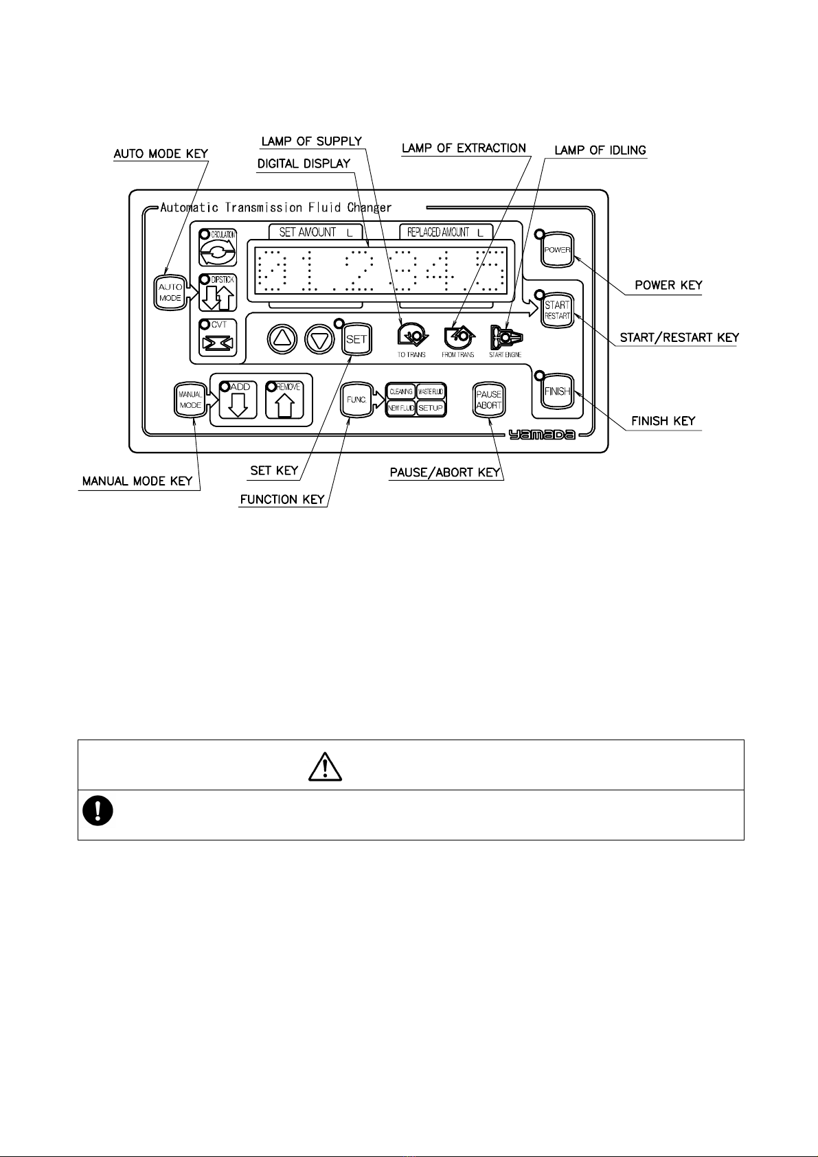
1-2. Operation panel ............................................................................................................. 2
1-3. Contents of package...................................................................................................... 2
2. Preparations before oil replacement
2-1. Setting a new oil pail ······································································································3
2-2. Taking out/Setting the wasted tank ················································································4
2-3. Connecting the flexible nozzle ·······················································································4
2-4.Setting up ························································································································5
3. How to use
3-1. Precautions ····················································································································6
3-2. Preparations for operation······························································································6
3-3. Inserting the flexible nozzle and notes ···········································································7
3-4. Car to be cared when inserting a nozzle for oil replacement·········································7
3-5.How to operate
3-5-1. Automatic mode······································································································8
■Circulation mode 8
■Dipstick (Alternate) mode ···························································································9
■CVT mode···················································································································10
3-5-2. Manual mode ··········································································································11
■Manual replacement of oil (Setting the amount of oil to be replaced) ························11
■Manual replacement of oil 2(manual) ·········································································12
3-5-3. Functions ················································································································13
■Cleaning······················································································································13
■Removing the waste oil·······························································································14
■Refilling new oil···········································································································15
■Setting·························································································································16
3-5-4. Other functions ·······································································································17
4. Maintenance and Inspection
4-1. Maintenance···················································································································19
4-2. Error Codes
■EO1【Oil removal error】······························································································20
■EO2【Insufficient flow rate for oil supply】【Insufficient flow rate for oil removal】········21
■EO3【Oil removal disabled】························································································22
■EO4【Oil removal error】······························································································23
■EO5【Setting error】·····································································································24
■EO7【Insufficient flow rate for oil removal】·································································25
■EO8【Oil removal disabled】························································································26
4-3. Troubleshooting··············································································································27
5. Main Dimensions···················································································································· 28
6. Specifications··························································································································· 29
7 .Parts list······································································································································· 30
7-1. Automatic transmission fluid changer(881082)······························································30
7-2. Cover assembly(854043) ·······························································································31
7-3. Flame assembly(854044)·······························································································32
7-4. Hose assembly(803619) ································································································33
7-5. Nozzle body assembly(804132)·····················································································34
7-6. Wasted oil tank assembly(804512) ················································································35
7-7. Base assembly(804514) ································································································36

4/4
7-8. Piping assembly(804515)·······························································································37
7-9.Oil sensor assembly(804518) ·························································································38
8. Option attachment ··················································································· 39
9.Limited warranty

1
1. Name of each part
1-1. Name of each part

2
1-2. Operation panel
1-3. What is in the package (See Figure 1-1 on page 1.)
Oil changer (this machine), flexible nozzle L1200, connection hose for oil circulation replacement (two), exhaust nozzle,
cleaning coupler, nozzle stand and setscrew (M6 × 35, for a nozzle stand) (two)
Operation manual
1. Use a lifter to unload the package from a truck.
2. Remove the wooden crate, and hold the grips located on both sides to unload this machine from the base.
3. Check to see if the machine is neither scratched nor damaged.
4. Check to see if all supplied parts are in the package.
5. Connect the power supply plug to the 220 V AC outlet. If the machine operates normally, the buzzer sounds and
the signal lights light.
CAUTION
-・When you lift this machine, hold the grips located on both sides of the main unit with two or more persons.
Do not tumble or drop this machine.

3
2. Preparations Before Oil Replacement
CAUTION
-This machine is exclusively designed for automatic transmission fluid (ATF) and engine oil. Do not use any
other solution or highly volatile fluid that damages rubber such as brake fluid, gasoline and light oil with this
machine. Or, it may cause the machine to not only malfunction but also catch fire.
-While this machine is operating or when you store it, be sure to lock the caster brakes. Or, the machine
located on the inclined plane may start moving, fall down to contaminate the facility or damage the car. In this
case, it is you who is responsible for the contamination and/or damage.
-Always handle this machine, a new oil pail, and the wasted oil tank cleanly. If you cannot manage them well, a
foreign substance or dust may get mixed in with the user’s car whose oil is to be replaced, and it may cause the
car to malfunction.
NOTE
If the temperature of the ATF or engine oil is low, the flexible nozzle cannot suck the fluid/oil well. Warm up the machine
sufficiently to raise the temperature of the fluid/oil before removing the fluid/oil. The guideline for the ATF or engine oil
temperature is approximately 50 to 80°C.
2-1 Setting a new oil pail
CAUTION
-To replace the new oil pail with a new one, check to see again if the oil type you selected at the place where
various types of lubricants are stored is correct before setting it.
-When you set a new oil pail, be careful so that any mud or dust cannot be stuck to the suction hose.
-Be sure to attach the pail guard onto the new oil pail. Or, the new oil pail may fall down and the spilt oil may
contaminate the facility.
1. Take out the suction hose, and insert it into the new oil pail. (See Fig. 2-1.)
2. Set the new oil pail inside the machine.
3. Check to see if the suction hose is not bent inside the new oil pail.
4. Set the pail guard.
NOTE
- If you attach the optional pail cover onto the pail, you can replenish the
machine with new oil from the oil drum or similar container without
replacing the oil pail.
Fig.2-1

4
2-2 Taking out/Setting the wasted oil tank
CAUTION
-Do not exhaust any wasted oil that is handled with this machine to the ground directly. Discard the wasted oil
according to the applicable law and regulations.
-Be sure to remove the wasted oil upper limit sensor with hands. If you pull it out forcibly, the connector is
damaged and/or the cable is broken.
-When you set the wasted oil tank, be careful so that any mud or dust cannot be stuck to the hose.
-Be sure to attach the tank guard onto the machine. Or a new oil pail may fall down and the spilt oil may
contaminate the facility.
1. Remove the tank guard from the rear of the machine, and pull out the hose
from the wasted oil tank.
2. Be sure to disconnect the wasted oil upper limit sensor cord from the
connector. (See Fig. 2-2.)
(If you take out the tank although the cord is not disconnected, the cord may
be broken.)
3. Remove the wasted tank cap, and discard the wasted oil into the regulated
wasted oil bath.
4. Set the wasted oil tank onto the machine base, and insert the hose into it.
5. Connect the wasted oil upper limit sensor to the connector.
(When connecting the sensor, face the dowel of the plug located on the edge
of the sensor cord toward the front to set the sensor.)
6. Attach the tank guard onto the machine.
NOTE
The later description of the operation (“If the wasted oil tank is totally full while the machine is operating” on page 17)
allows you to exhaust the wasted oil without taking out the wasted oil tank.
2-3 Connecting the flexible nozzle
CAUTION
When you connect the nozzle and the hose, do not mistake the hose for
new oil (red) for that for the wasted oil (black) or vice versa. If you do not
connect them correctly, a foreign substance such as dust gets mixed in with
the machine, and it may cause the machine to malfunction. (See Fig. 2-3.)
1. Pull the outer ring of the coupler located on the hose toward your side.
2. Insert the connector of the nozzle into the coupler, and replace the ring. The connector is fixed.
3. Pull the hose and the nozzle to check to see if they are not disconnected.
Fig.2-2
Fig.2-3

5
2-4 Setting up
CAUTION
-While the machine is operating, be sure to lock the caster brakes on the flat place. Or, the machine may start
moving depending on the installation place, and it may cause a property damage accident.
-Do not use any power supply other than 220 V AC for the machine. Or it may cause the machine to
malfunction and damage it due to electrical shock or fire.
-Do not expose the machine to direct sunlight for a long time. It may cause the resin parts to deform due to
heat.
1. Stop the car at a horizontal place, and yank the emergency
brake fully to check to see if the braking function operates well.
2. Move the machine next to the car, and lock the caster brakes. (See Fig. 2-4.)
3. Connect the power cable to the 220 V AC outlet, and check
that the buzzer sounds.
4. Before oil replacement, be sure to check the amount of oil with
the level gauge of the car.
Fig.2-4

6
3. How to Use
3-1 Precautions
caution
-Since the oil to be used is regulated depending on the car type such as a 4-wheel drive car, check it with the
operating instructions of the car. (If you use any oil other than the designated ATF, it may cause the
transmission to malfunction.)
-Some cars may use a nozzle holder. Contact the dealer or our sales office. (The “upright engine” of some
cars such as a Honda has the short level gauge, and so the nozzle may be inserted into such a type of car at
an angle. In this case, the tip of the nozzle is in contact with the rotating section of the inside and it may
damage the rotating section. To replace the ATF of such a type of car, be sure to use the nozzle holder.)
-After operating the machine, be sure to check the oil amount with the level gauge. (After replacement of oil,
be sure to check the amount of oil with the level gauge of the car so that the amount of oil can be neither too
much nor too little. Note that if the amount of oil is too much or too little, it may damage the transmission.)
3-2 Preparations for operation
CAUTION
-You are supposed to have to measure the amount of oil after tuning off its engine depending on a car type.
-Insert the level gauge fully to prevent any foreign substance such as dust from getting mixed in with the
transmission.
1. Set the shift lever to the position “P”, and idle the engine for ten to fifteen minutes to raise the oil
temperature (50 to 80°C). (See Fig. 3-1.)
When you replace the oil of a CVT (Continuously Variable Transmission) type of car, drive it for
a while.
2. Idle the engine and move the shift lever from “P” to “L” while stepping on the brake, then to “N”.
3. In this condition, pull out the level gauge. Wipe off the level gauge with a waste cloth, and
measure the amount of oil again.
4. When the oil temperature of the transmission is high immediately after you drive
the car, check the HOT side of the level gauge. Immediately after the engine
rotates, check the COLD side. In either case, when the oil is located between
the “LOW” mark and the “FULL” mark, it indicates the normal condition.
The oil check at this point shall be conducted to know the guideline for the
regulated amount of oil to be supplied by checking the difference between the
supplied oil and the collected oil at replacement. (See Fig. 3-2.)
Fig.3-1
Fig. 3-2

7
3-3 Inserting the flexible nozzle and notes
Insert the nozzle into the level gauge hole slowly and securely. (See Fig. 3-3.)
NOTE
-Never push the nozzle into the hole forcibly. If the nozzle stops
in the middle, pull it back a little and then push it into the hole
while turning it slowly.
-Judge how deeply you should insert the nozzle from the length of
the oil gauge.
-Stop pushing the nozzle when it hits something.
-If you do not feel the nozzle hit anything, pull out the nozzle by
approximately 10 cm, and push it into the hole slowly again.
-If the car does not allow the nozzle to be pulled out, be careful to
insert the nozzle into the level gauge hole. Read the following
description for such a car.
3-4 Car to be cared when inserting a nozzle for oil replacement
Please purchase an optional nozzle holder separately for a car except for some Honda cars.
Fig. 3-3

8
3.5 How to operate *(The description written in “Italics” explains the condition of the automatic operation.)
3-5-1 Automatic mode
■Circulation mode
1. Connect the power cable to the AC outlet. (The buzzer sounds for one second.)
2. Press the POWER key.
3. Press the AUTO MODE key once and select “CIRCULATION” mode.
4. Set the amount of oil to be replaced with the ▲key and/or the▼key, and press the SET key.
Insert the nozzle into the level gauge hole securely.
Attach the connection hoses to the oil cooler lines.
When you hold down the SET key (for two seconds),
the machine enters “Quick mode”.
5. Insert the flexible nozzle into the level gauge hole,
and connect the automatic valve to the hoses.
6. Press the START key.
When the machine is set to “クイック,”
it starts operating from Step 10.
7. All the wasted oil is removed from the oil pan.
8.Supply the car with new oil whose amount is 7 + the
checked amount.
9. Start idling the engine.
10. The flow rate of the oil cooler line is checked.
11.While removing oil from the oil cooler line, the same amount of new oil is
supplied the car.
12. When the remaining time becomes approximately 30 seconds, the signal light “blue” flashes (lights during
operation).
When the machine is in Quick mode
Digital display: “クイック” appears on the display.
Insert the nozzle into the level gauge hole securely.
Attach the connection hoses to the oil cooler lines.
Start idling the engine.

9
13. When the amount of the supplied oil and that of the removed oil reach the set amount, the automatic operation
finishes.
Stop idling the engine.
14. Check the level gauge, and make fine adjustments of oil replacement if the amount of the replaced oil is too much or
too little.
■Dipstick (Alternate) mode
1. Connect the power cable to the AC outlet. (The buzzer sounds for one second.)
2. Press the POWER key.
3. Press the AUTO MODE key twice to select the Dipstick mode.
4. Set the amount of oil to be replaced with the ▲key and/or the
▼key, and press the SET key.
Insert the nozzle into the level gauge hole securely.
Start idling the engine.
When you hold down the SET key
(for two seconds), the machine enters “Light car mode”.
5. Insert the flexible nozzle into the level gauge hole,
and start idling the engine.
6. Press the START key.
7. Remove the regulated amount of wasted oil (You can change the amount
of wasted oil to be removed for the first time. See “P02: Amount of oil to
be removed from a light car for the first time” of Section “Setting” on page
16). (In Light Car mode only)
8. Supply the car with the regulated amount of new oil.
9. Wait for a certain time period.
10. Remove the regulated amount of wasted oil.
11. Repeat operations form Step 8 to 10.
When you are to replace the oil of a light car,
the oil may overflow from the oil pan if you
supply it with new oil without doing anything.
Therefore, remove the oil from the oil pan at
first in “Light car mode”.
When you replace the wasted oil of a light car with new one
Digital display: “ケイジドウシャ” appears on the screen.
Insert the nozzle into the level gauge securely.
Start idling the engine.

10
12. The signal light “blue” flashes when the remaining time becomes approximately 30 seconds.
13. Oil replacement finishes when the amount of new oil and that of wasted oil reach the value you set.
Stop idling the engine.
14. Check the level gauge, and make fine adjustments if the replaced oil is too much or too little.
Number of alternate replacement operations and waiting time varying depending on the amount of oil to be replaced
you set
Set value
Amount of oil to be
replaced at a time
Number of
replacements
Waiting time*
Total replacement time**
3 L 600 mL
5 times
10 seconds
Approximately 4 minutes
4 L 800 mL
5 times
10 seconds
Approximately 5 minutes
5 L or more
1000 mL
5 times (When you
set “5 L”)
15 seconds
Approximately 6 minutes and 30 seconds or more
* You can change the waiting time. See “P04: waiting time for alternate oil replacement” of Section “Settings” on page
16.
** These values are applicable when the temperature of new ATF is 20°C. (Use these values as the guideline only
because the replacement time varies depending on the oil type and the temperature condition.)
■CVT mode
1. Connect the power cable to the AC outlet. (The buzzer sounds for one second.)
2. Press the POWER key.
3. Press the AUTO MODE key three times to select CVT mode.
4. Press the SET key.
Insert the nozzle into the level gauge hole securely.
When you hold down the SET key
(for approximately two seconds), the machine enters “Semi Auto mode.”
5. Insert the flexible nozzle into the level gauge hole.
6. Press the START key.
7. Remove the wasted oil until the oil pan gets empty.
When the machine is in Semi-Auto mode
Digital display: “セミオート”appears on
the display.
Insert the nozzle into the level gauge
hole securely.

11
When the machine is in Normal mode, the machine automatically skips to Step 10.
8
.
The NEW FLUID lamp and the FINISH key flash. (These lamp and key flash only
when the machine is in Semi Auto mode.)
9. To finish replacing the oil, press the FINISH key.
To supply the car with new oil whose amount is the same as that of the removed oil, press the MANUAL MODE key,
then press the START key.
10.
Supply the car with new oil whose amount is the same as that of the removed wasted oil.
11
.
The signal light “blue” flashes when the remaining time becomes approximately 30 seconds.
12. Check the level gauge, and make fine adjustments if the replaced oil is too much or too little.
3-5-2 Manual mode
■Manual replacement of oil (Setting the amount of oil to be replaced)
1. Connect the power cable to the AC outlet. (The buzzer sounds for one second.)
2. Press the POWER key.
3. Press the MANUAL MODE key once and select “ADD” or
press the MANUAL MODE key twice and select “REMOVE.”
4. Set the amount of oil to be replaced with the ▲key and/or the▼key, and press the SET key.
Perform this operation when “0.5” or more is displayed as the amount of oil.
5. Insert the flexible nozzle into the level gauge hole.
6. Press the START key.
7.
New oil is supplied to the car (or the wasted oil is removed from the car).
8.The signal light “blue” flashes when the remaining time becomes approximately 30 seconds.
9. Oil replacement finishes when the amount of the supplied oil reaches the value you set.
(If the wasted oil is removed, the operation finishes when the set amount of wasted oil is removed or the all wasted oil
is removed from the oil pan.)

12
■Manual replacement of oil 2 (manual)
1. Connect the power cable to the AC outlet. (The buzzer sounds for one second.)
2. Press the POWER key.
3. Press the MANUAL MODE key once and select “ADD” or press the MANUAL MODE key twice and select
“REMOVE”.
4. Press the SET key without setting any amount of oil to be replaced (“---“ appears on the digital display).
Perform this operation when the set value is “---.”
5. Insert the flexible nozzle into the level gauge hole.
6. Hold down the START button.
7. Only while you are holding down the START key, oil is supplied to the car (or removed from the car).
8. When you release the START key, the machine stops supplying or removing the oil.
(When you hold down the START key again, you can supply the machine with oil (or remove oil from the machine).

13
3-5-3 Functions
■Cleaning
This function returns new oil remaining in the new oil hose or pipe into a new oil pail. This operation eliminates waste
of any new oil when you replace new oil with another type of new oil.
1. Connect the power cable to the AC outlet. (The buzzer sounds for one second.)
2. Press the POWER key.
3. Press the FUNC. key once, and select “CLEANING.”
“クリーニング” appears on the digital display.
4. Press the SET key.
Connect the machine to the cleaning coupler.
5. Connect the cleaning coupler to the red side of the twin-hose.
6. Press the START key.
7.
Collect new oil remained in the hose or pipe into a new oil pail.
8. The machine stops automatically. Disconnect the cleaning coupler, and then connect the flexible nozzle to the
machine.
caution
-・When you clean the hose or pipe, be sure to connect the cleaning coupler to the machine.
Or a foreign substance or dust may get mixed in with the machine, and it may cause the
machine to malfunction.

14
■Removing the wasted oil
1. Connect the power cable to the AC outlet. (The buzzer sounds for one second.)
2. Press the POWER key.
3. Press the FUNC. Key twice and select “WASTE FLUID.
“ハイシュツ” appears on the digital screen.
4. Press the SET key.
Replace the nozzle with one for the wasted oil.
Press the START key to start removing the wasted oil from the car.
5. Connect the exhaust nozzle to the black side of the twin-hose, and press the START key.
6.
Remove the wasted oil.
7. When the wasted oil tank gets empty, the machine automatically stops. Disconnect the exhaust nozzle, and
connect the flexile nozzle to the machine.
caution
・Do not exhaust the wasted oil to be handled with this machine to the ground directly.
Handle the wasted oil according to the applicable law and/or regulations.

15
■Refilling new oil (An optional pail cover is required to use this function.)
1. Connect the power cable to the AC outlet. (The buzzer sounds for one second.)
2. Press the POWER key.
3. Press the FUNC. key three times, and select “NEW FLUID.”
“ホキュウ” appears on the digital display.
If you do not attach the pail cover onto the machine, you cannot select this function.
4. Press the SET key.
Replace the nozzle with one for new oil.
5. Replace the attached hose with the filter hose, and press the START key.
6.
Refill a new oil pail with new oil.
7. When a new oil pail is filled with new oil, the machine automatically stops. Disconnect the filter hose from the
machine, and connect the flexible nozzle to the machine.
caution
・To refill a new oil pail with new oil, be sure to attach the filter hose to the machine.
Or, a foreign substance or dust gets mixed in with the machine, and it may cause the
machine to malfunction.
This manual suits for next models
1
Table of contents
Popular Other manuals by other brands

Husqvarna
Husqvarna DS250 Series Operator's manual

Marcato
Marcato Ampiamotor Instructions for use and maintenance

RSLogger
RSLogger PRO user manual

Balluff
Balluff ProfiNet BIS M-4008-048-001-ST4 installation guide

Idex
Idex Class 1 ITL 40 Operation manual

Behringer
Behringer Airplay Guitar ULG10 quick start guide