Novus LogBox Wi-Fi User manual

NOVUS AUTOMATION 1/53
LogBox Wi-Fi
INSTRUCTION MANUAL V1.0x E
FCC
This device has been tested and complies with the parameters for a Class A digital device, pursuant to Part 15 of the FCC Rules. Such limits are
designed to provide reasonable protection against harmful interference when the device is operated in a commercial environment. This device
generates, uses, and can radiate radio frequency energy and, if not installed and used in accordance with the instructions in this manual, may
cause harmful interference to radio communications.
Any changes or modifications not expressly approved by the party responsible for compliance could void the user’s authority to operate the device.
RF Exposure: It is necessary to keep 20 cm between the antenna and the user and the transmitter module cannot be co-located with any other
transmitter or antenna.
Canada
This Class A device complies with Canadian standard ICES-003.
Cet appareil numérique de la classe A est conforme à la norme NMB-003 du Canada.
CE Mark
This is a Class A device. In a domestic environment, it may cause radio interference and require the user to take proper measures.
ANATEL
This device is homologated by ANATEL, in accordance with the procedures regulated by Resolution 242/2000, and meets the technical
requirements applied.
This device is operated in a secondary fashion, that is, it is not entitled to protection against harmful interference, even from the same type of
stations, and it cannot cause interference to systems operating on a primary basis.
For more information, see the ANATEL website www.anatel.gov.br.

NOVUS AUTOMATION 2/53
1. SAFETY ALERTS........................................................................................................................................................................................4
2. INTRODUCTION .........................................................................................................................................................................................5
3. DISPLAY AND NAVIGATION......................................................................................................................................................................6
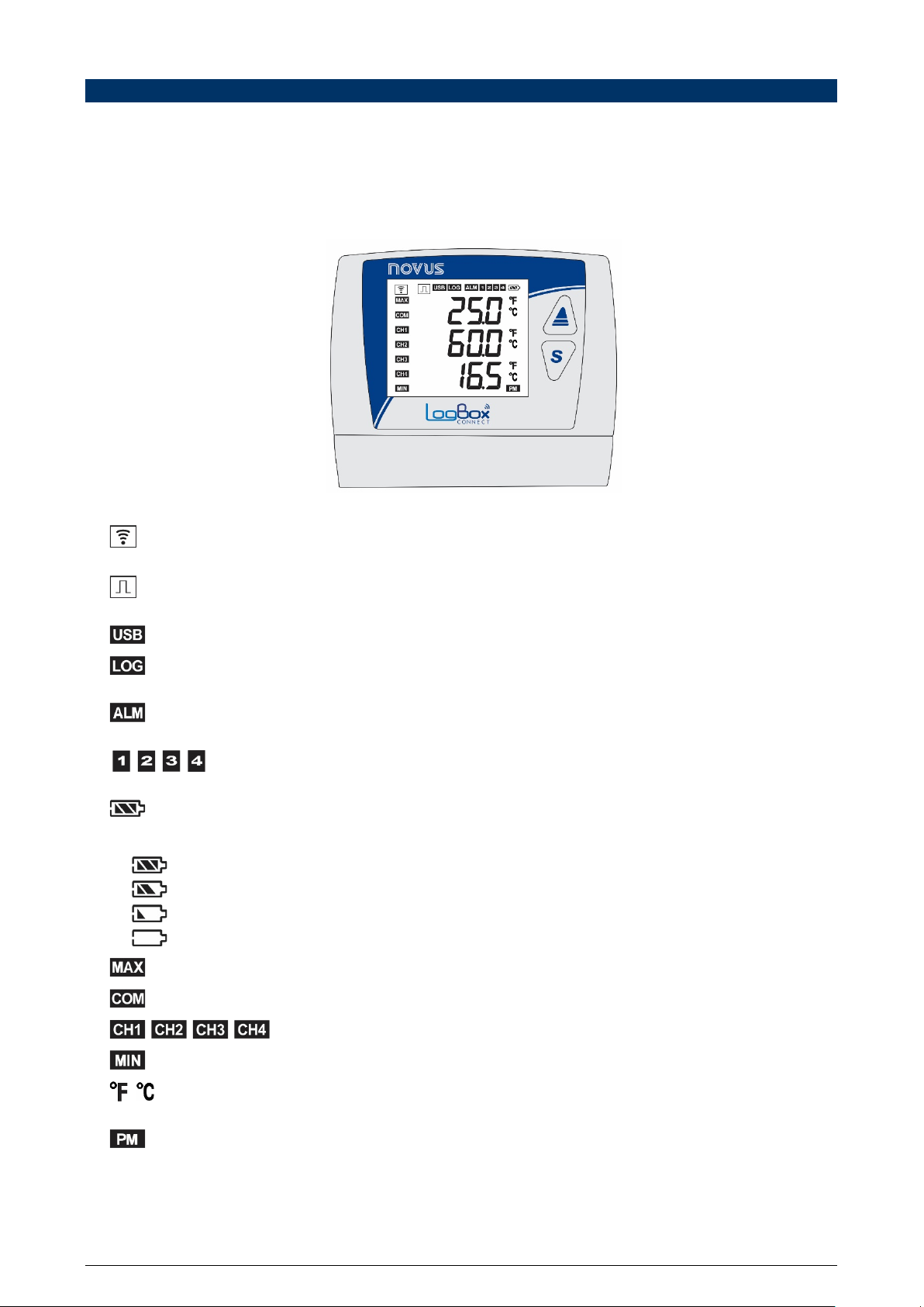
3.1 DISPLAY INFORMATION ...........................................................................................................................................................................6
3.2 OPERATION KEYS.....................................................................................................................................................................................7
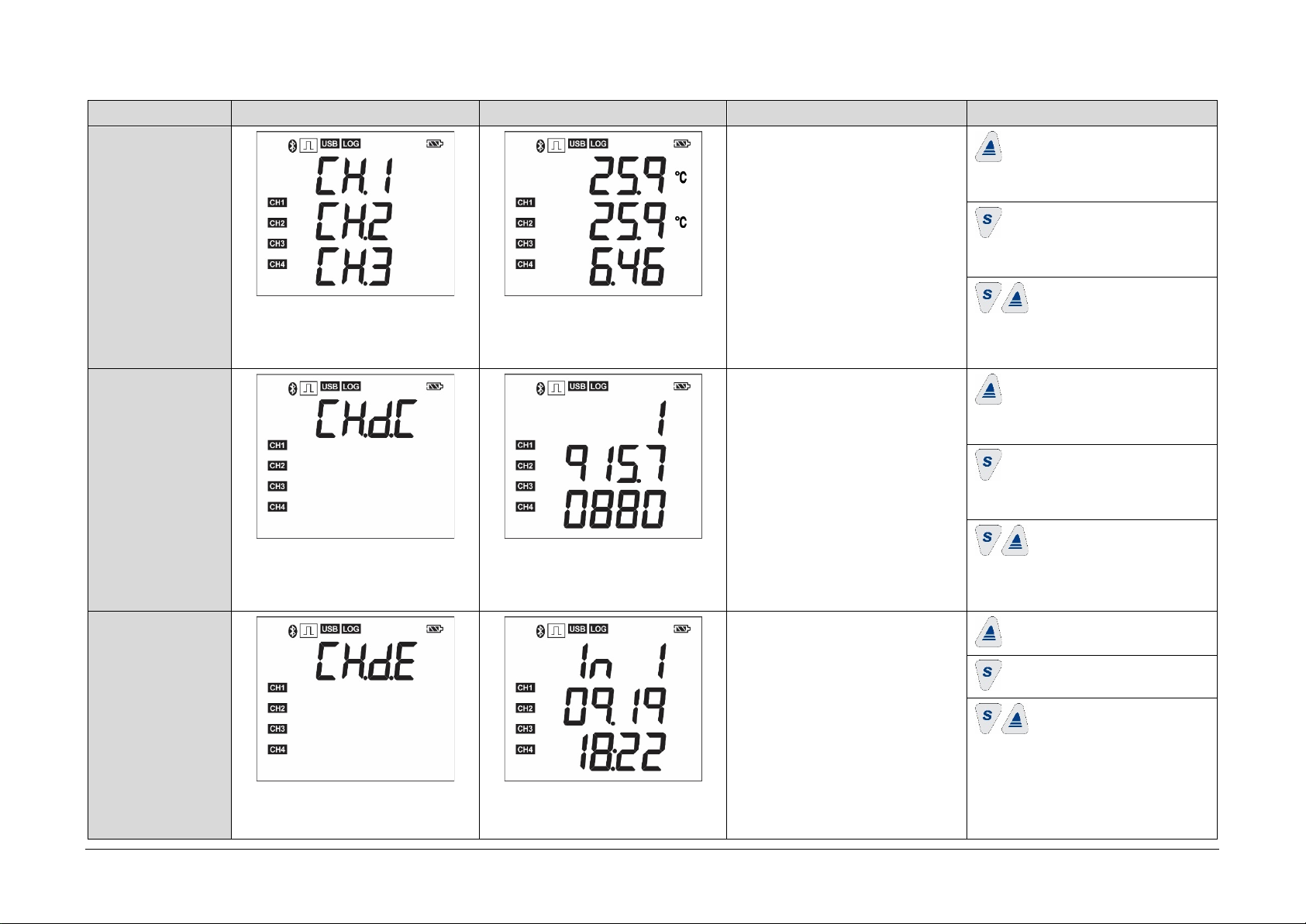
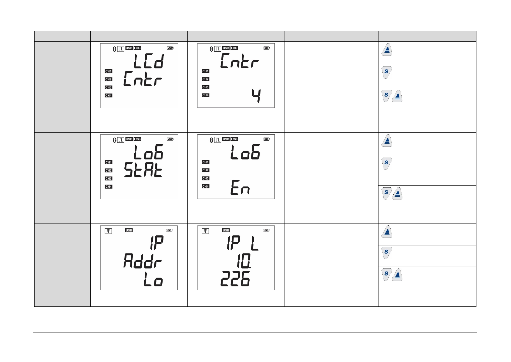
3.3 NAVIGATION KEYS....................................................................................................................................................................................7
4. OPERATION AUTONOMY........................................................................................................................................................................12
5. INPUT SIGNALS READING......................................................................................................................................................................13
5.1 ANALOG INPUTS......................................................................................................................................................................................13
5.1.1 MEASUREMENT AND INDICATION OF INPUT TYPES .........................................................................................................................14
5.2 DIGITAL INPUT.........................................................................................................................................................................................16
5.2.1 PULSE COUNT .........................................................................................................................................................................................16
5.2.2 EVENT LOG ..............................................................................................................................................................................................17
5.2.3 LOGS CONTROL ......................................................................................................................................................................................17
6. DIGITAL OUTPUT.....................................................................................................................................................................................18
7. MQTT PROTOCOL ...................................................................................................................................................................................19
7.1 PUBLICATION TOPICS ............................................................................................................................................................................19
7.1.1 STATUS TOPICS ......................................................................................................................................................................................19
7.1.2 LOGS TOPICS ..........................................................................................................................................................................................19
7.1.3 CONFIGURATION TOPIC ........................................................................................................................................................................19
7.1.4 RESPONSE TOPIC...................................................................................................................................................................................19
7.1.5 IDENTIFICATION TOPIC ..........................................................................................................................................................................19
7.2 INSCRIPTION TOPIC................................................................................................................................................................................20
7.3 FRAME PARAMETERS ............................................................................................................................................................................21
7.3.1 TIMESTAMP..............................................................................................................................................................................................22
7.4 MQTT PROTOCOL CONFIGURATION IN SOFTWARE NXPERIENCE .................................................................................................22
7.4.1 QOS...........................................................................................................................................................................................................22
7.4.2 JSON FORMAT.........................................................................................................................................................................................22
7.4.3 BOOLEAN FORMAT .................................................................................................................................................................................23
8. MODBUS-TCP PROTOCOL .....................................................................................................................................................................24
8.1 COMMANDS .............................................................................................................................................................................................24
8.1.1 READ HOLDING REGISTERS – 0X03 .....................................................................................................................................................24
8.1.2 WRITE HOLDING REGISTERS – 0X06 ...................................................................................................................................................24
8.1.3 WRITE MULTIPLE HOLDING REGISTERS – 0X16.................................................................................................................................24
8.2 REGISTERS TABLE..................................................................................................................................................................................24
9. DATA LOGGING .......................................................................................................................................................................................30
10. ALARMS ....................................................................................................................................................................................................31
11. CONFIGURATION SOFTWARE...............................................................................................................................................................32
11.1 CONFIGURING LOGBOX WI-FI WITH NXPERIENCE ............................................................................................................................32
11.1.1 GENERAL PARAMETERS........................................................................................................................................................................32
11.1.2.1 INFORMATION......................................................................................................................................................................................... 32
11.1.2.2 DISPLAY................................................................................................................................................................................................... 32
11.1.2.3 CLOCK .....................................................................................................................................................................................................32
11.1.2 ANALOG CHANNELS PARAMETERS .....................................................................................................................................................33
11.1.2.1 CUSTOM CALIBRATION.........................................................................................................................................................................33
11.1.3 DIGITAL CHANNEL PARAMETERS.........................................................................................................................................................34
10.1.3.1 PULSE COUNT MODE ............................................................................................................................................................................ 34
10.1.3.2 EVENT LOG OR LOGS CONTROL MODE ............................................................................................................................................. 35
11.1.4 CHANNELS’ GENERAL PARAMETERS ..................................................................................................................................................35
11.1.5 DATA LOGGING CONFIGURATION ........................................................................................................................................................36
11.1.5.1 LOGS........................................................................................................................................................................................................ 36
11.1.5.2 START MODE .......................................................................................................................................................................................... 36
11.1.5.3 STOP MODE ............................................................................................................................................................................................ 36
11.1.6 COMMUNICATION PARAMETERS..........................................................................................................................................................37
11.1.6.1 WI-FI CONFIGURATION.......................................................................................................................................................................... 37
11.1.6.2 MQTT PROTOCOL .................................................................................................................................................................................. 37
11.1.6.3 MODBUS-TCP PROTOCOL .................................................................................................................................................................... 38
11.2 DIAGNOSTICS ..........................................................................................................................................................................................38
11.2.1 DATA LOGGING .......................................................................................................................................................................................38
11.2.2 CHANNELS ...............................................................................................................................................................................................39
11.2.3 MISCELLANEOUS ....................................................................................................................................................................................39
12. INSTALLATION .........................................................................................................................................................................................41
12.1 MECHANICAL INSTALLATION ................................................................................................................................................................41
12.1.1 DIMENSIONS............................................................................................................................................................................................42

NOVUS AUTOMATION 3/53
12.2 ELECTRICAL INSTALLATION..................................................................................................................................................................43
12.2.1 INSTALLATION RECOMMENDATIONS...................................................................................................................................................43
12.2.2 SPECIAL PRECAUTION...........................................................................................................................................................................43
12.2.3 ELECTRICAL CONNECTIONS.................................................................................................................................................................43
12.2.3.1 POWER SUPPLY.....................................................................................................................................................................................43
12.2.3.2 DIGITAL OUTPUT.................................................................................................................................................................................... 44
12.2.3.3 DIGITAL INPUT........................................................................................................................................................................................44
12.2.3.4 ANALOG INPUTS.....................................................................................................................................................................................45
13. COMMUNICATION INTERFACES............................................................................................................................................................46
13.1 USB ...........................................................................................................................................................................................................46
13.2 WI-FI..........................................................................................................................................................................................................46
14. OVER THE AIR (OTA) FIRMWARE UPDATE ..........................................................................................................................................47
15. CFR 21 REGULATION..............................................................................................................................................................................48
15.1 SUPPORT FOR CFR 21 PART 11 AND RDC 17:2010 VALIDATION......................................................................................................48
16. TROUBLESHOOTING ..............................................................................................................................................................................49
16.1 START/STOP MODES..............................................................................................................................................................................49
16.2 CLOCK ......................................................................................................................................................................................................49
16.3 ALARM INFORMATION ............................................................................................................................................................................49
16.4 ANALOG INPUTS......................................................................................................................................................................................49
16.5 UNREGISTERED ALARMS ......................................................................................................................................................................49
16.6 COMMUNICATION LINK LOSS................................................................................................................................................................49
17. TECHNICAL SPECIFICATIONS ...............................................................................................................................................................50
17.1 SENSORS RANGE AND ACCURACY .....................................................................................................................................................51
18. WARRANTY ..............................................................................................................................................................................................53

NOVUS AUTOMATION 4/53
1. SAFETY ALERTS
The symbols below are used throughout this manual to draw the user’s attention to important information regarding safety and use of the device.
CAUTION
Read the manual fully before installing
and operating the device.
CAUTION OR HAZARD
Risk of electric shock.
ATTENTION
Material sensitive to static charge. Check
precautions before handling.
Safety recommendations should be observed to ensure user safety and to prevent damage to the device or system. If the device is used in a
manner other than that specified in this manual, the safety protections may not be effective.

NOVUS AUTOMATION 5/53
2. INTRODUCTION
LogBox Wi-Fi is an electronic wireless data register, also known as a data logger, which comprises three analog sensors and one digital sensor,
respectively called the "analogue measuring channel" and the "digital measuring channel". With a memory capacity for up to 140,000 logs, it allows
the use of batteries, to keep its autonomy and continue to log data even during external power outages. It features a large display that offers a
comfortable view of measured variables and general device information. Furthermore, the device’s enclosure has a protection cover for the
connections, a sealing ring and a holder that allows its attachment to a wall or metal surface by means of the optional bracket with magnetic inserts.
The analog inputs accept any type of temperature sensor, such as thermocouples, Pt100 or sensors for any other quantities with current or voltage
signals. The digital channel can log the time of events, such as opening a door, or counting pulses from a flow sensor. LogBox Wi-Fi also has the
following internal sensors: temperature, battery voltage, and external power supply voltage, which can also log the values in the memory, taking the
place of any of the available measurement channels. Its wide display allows you to view up to three variables simultaneously, and displays
indications such as alarms, communication status, enabled channels, battery voltage level, among other information.
LogBox Wi-Fi also has a buzzer for audible alerts and a digital output that can be used as an alarm output or as an electronic key to power
sensors and can be controlled by several protocols, such Modbus-TCP and MQTT, for example.
The device’s configuration can be accessed through a desktop or a notebook connected to its USB interface. For use with computers, NOVUS
provides the NXperience software in your website’s download area. NXperience enables the logs’ configuration, download, and analysis, as well
as allowing them to be published in the NOVUS Cloud for remote viewing.

NOVUS AUTOMATION 6/53
3. DISPLAY AND NAVIGATION
3.1 DISPLAY INFORMATION
LogBox Wi-Fi has an LCD display with 3 numerical lines of 4 ½ digits, to display the current value of all enabled channels, as well as the minimum
and maximum values thereof. At the same time, it is possible to display the current value of up to three analog channels and, in a second screen, if
enabled, the digital input current value. In addition to channel information, LogBox Wi-Fi has 7 screens with a variety of information and features
and 24 symbols that allow for easy information visualization and diagnostics.
See below an illustration of the display with a description of each symbol’s functionality.
Fig. 01 – LogBox Wi-Fi Display Information
●: It remains lit while LogBox Wi-Fi has a valid IP on the wireless network to which you are connected. If the device is set to wake up by
keyboard, it will remain on while the interface remains available.
●: When the digital channel is disabled, it remains off. When set to "Pulse Count" mode, it will remain on. When set in the "Event Log" or
"Logs Control" modes, it will remain lit, flashing when an event is detected at the digital input.
●: Lights up when the USB cable is connected. Turns off when the USB cable is disconnected.
●: It remains lit from the moment the device registers the first log until the moment it stops logging. When set to "Daily" mode, which must
start and end daily at a predetermined time, it will remain lit within the set time. It will flash while logging, turn off at the time of a log and restart.
●: Lights up and stays on when entering an alarm condition. Turns off when a new configuration is received, or the alarm status is
cleared. Indicates to the user that, at some point, an alarm has been triggered.
●, , , : Light up while the alarm conditions of the corresponding channels are satisfied: 1 (analog channel 1), 2 (analog channel 2),
3 (analog channel 3) and 4 (digital channel). When you exit the alarm condition, the flag will be cleared.
●: Indicates the battery voltage level. This symbol is updated next to the log range (even if the device is not logging), with a minimum of 5
minutes. Thus, if the device is configured to log every 1 second, the battery indicator will refresh every 5 minutes. If the logging interval is
longer than 5 minutes, the battery indicator will update with the same log range.
o: Battery over 75%;
o: Battery over 50%;
o: Battery over 25%;
o: Battery below 25% (provide battery replacement).
●: Lights up while the "Maximum" values information reached in each channel are being displayed.
●: Flashes to inform the receipt of valid data packet from one of the available communication interfaces.
●, , , : Indicates which channels are enabled.
●: Lights up while the "Minimum" amount of information is being displayed.
●, : If the channel unit is set to °F or °C, one of the symbols will light up during channel display. Otherwise, no unit symbol will be
displayed.
●: If the clock is set in the 12-hour format, the PM symbol will light up when the clock is displayed, and the time is later than 1 pm.

NOVUS AUTOMATION 7/53
3.2 OPERATION KEYS
To navigate between the screens, LogBox Wi-Fi has 2 keys: . Each key, depending on the current navigation screen, has two or more
features:
●Short touch (less than 2 seconds):
○Proceeds to the next screen if the current screen mnemonic is being displayed.
○Displays the mnemonic of the current screen again if the screen information is being displayed.
●Long touch (longer than 2 seconds or held down):
○Takes an action within the current screen.
●Both keys held down (longer than 2 seconds or held down):
○Takes a second action within the current screen.
If the buzzer is active, pressing any key will mute it.
3.3 NAVIGATION KEYS
To streamline information identification on each screen, a mnemonic, which will remain visible for two seconds, will be displayed when pressing a
key. If no key is pressed for this period, the information on the current screen will be displayed. If the key or the key is pressed while a
mnemonic is being displayed, the device will advance to the next screen or return to the previous one, which will be properly specified by their
mnemonics.
When the device is displaying the information on a screen, simply press any of the two keys to make the mnemonic appear again. To access the
desired screen, just wait two seconds.
The table below shows all screens, mnemonics, and information about them, the description of each information and keys function of each screen
available in the device.

NOVUS AUTOMATION 8/53
SCREEN MNEMONIC INFORMATION DESCRIPTION KEYS FUNCTION
1. Analog Inputs
Displayed for two seconds before accessing
the "Analog Inputs" screen.
This screen will be updated by the log range
and/or by the display update.
Displays the current value of the analog
channels and allows the display of the
maximum and minimum values reached by
each channel.
Line 1: Analog channel 1 value.
Line 2: Analog channel 2 value.
Line 3: Analog channel 3 value.
Key held down or long touch: Informs
the maximum value reached in each analog
channel.
Key held down or long touch: Informs
the minimum value reached in each analog
channel.
Both keys held down: Clears the
alarm statuses and the minimum and
maximum values reached by each analog
channel.
2. Digital Input
a. Pulse Count
Displayed for two seconds before accessing
the "Digital Input - Pulse Count" screen.
This screen will be
updated by the logs
range.
When enabled and configured on Pulse
Count mode, it displays the flow recorded in
the pulse count of the last record period for
the digital channel. If this option is not
configured, this screen will not be shown.
Uses the three display lines to display the
flow in the user unit with the number of
configured decimal places.
Key held down or long touch: Informs
the maximum flow reached in the pulse count
for the digital input.
Key held down or long touch: Informs
the minimum flow reached in the pulse count
for the digital input.
Both keys held down: Clears the
alarm statuses and the minimum and
maximum values reached in the pulse count
for the digital input.
2. Digital Input
b. Event Log or
Logs Control
Displayed for two seconds before accessing
the "Digital Input -
Event Log or Record
Control" screen.
This screen will be updated for each event
detected at the digital input.
When enabled and configured in the "Event
Log" or "Record Control" modes, it displays
the last detected event on the digital input.
If these options are not configured, this
screen is not displayed.
Line 1: Edge detected in event: 0 – Falling
edge; 1 – Rising edge.
Line 2: Month.Day of the event.
Line 3: Hour:Minute of the event.
Key held down or long touch: No action.
Both keys held down: No action.

NOVUS AUTOMATION 9/53
SCREEN MNEMONIC INFORMATION DESCRIPTION KEYS FUNCTION
3. Log Memory
Displayed for two seconds before accessing
the "Log Memory" screen.
This screen will be updated by the logs
range.
Displays the number of logs in the memory
and free memory percentage.
Line 1 and 2: Number of logs recorded in
the memory.
Line 3: Free memory percentage.
Key held down or long touch: No action.
Both keys held down: No action.
4. Date/Time
Displayed for two seconds before accessing
the "Date/Time" screen.
This screen will be updated by the log range
and/or by the display update.
Displays the device’s current date and time.
Line 1: Year.
Line 2: Month.Day.
Line 3: Hour:Minute.
Key held down or long touch: No action.
Both keys held down: No action.
5. Information
Displayed for two seconds before accessing
the "Information" screen.
This screen is static and always has the
same value for the same device.
Displays device information.
Line 1 and 2: Serial Number.
Line 3: Firmware Version.
Key held down or long touch: No action.
Both keys held down: No action.

NOVUS AUTOMATION 10/53
SCREEN MNEMONIC INFORMATION DESCRIPTION KEYS FUNCTION
6. Display Contrast
Adjustment
Displayed for two seconds before accessing
the "Display Contrast Adjustment" screen.
This screen will be updated whenever the
display contrast is adjusted.
Displays the contrast level configured for
the display and allows adjustment of the
display.
Line
3: Current contrast value. Can be
adjusted from 0 to 7.
Key held down or long touch: Increases
contrast (maximum of 7).
Key held down or long touch:
Decreases contrast (minimum of 0).
Both keys held down: No action.
7. Log Status
Displayed for two seconds before accessing
the "Log Status" screen.
This screen will be updated whenever the
current log status is changed.
Displays the current log status and allows
them to be started and/or paused if the
device is configured to allow keyboard start
and/or end.
En
– Enabled logs.
Dis
– Disabled logs.
Key held down or long touch: Initiates
logs if "By Keyboard" start mode is enabled.
Key held down or long touch: Pause
records if the "By Keyboard" end mode is
enabled.
Both keys held down: No action.
8. IP Low
Displayed for two seconds before accessing
the "IP Low" screen.
This screen will be updated whenever the IP
is changed.
Displays the last two octets of the
configured IP address. Key held down or long touch: No action.
Key held down or long touch: No action.
Both keys held down: No action.

NOVUS AUTOMATION 11/53
9. IP High
Displayed for two seconds before accessing
the "IP High" screen.
This screen will be updated whenever the IP
is changed.
Displays the first two octets of the
configured IP address. Key held down or long touch: No action.
Key held down or long touch: No action.
Both keys held down: No action.
10. Wi-Fi Signal
Strength
Displayed for two seconds before accessing
the "Wi-Fi LQI" screen.
This screen will be updated according to the
Wi-Fi signal strength.
Displays the signal strength between the
device and the Wi-Fi access point. Key held down or long touch: No action.
Key held down or long touch: No action.
Both keys held down: No action.
Table 01 – Navigation Keys

NOVUS PRODUTOS ELETRÔNICOS LTDA. 12/53
4. OPERATION AUTONOMY
LogBox Wi-Fi is powered by an external power supply, with a 10 to 30 VDC input, or USB port. The device can optionally be powered by four
standard "AA" batteries (1.5 V each) which, in the event of a power failure in the power supply source, will keep it running for at least two years. In
this case, to reduce consumption, the Wi-Fi interface will be disabled. All other features, however, will remain in operation for at least one year.
When power from the power supply source is restored, the Wi-Fi interface will be activated, and the data logged in memory during the power
interruption will be published in the services that support backup.
While the device is operated by batteries, very high temperatures (above 30 °C) or too low (below 10 °C) will cause battery chemistry to react
outside typical operating characteristics, reducing battery life. Thus, when operating the device in these ranges, consider that the two-year
expectation can be reduced considerably.
While the device is operating on batteries, temperatures too high (above 30 °C) or too low (below 10 °C) will make the LogBox Wi-Fi circuit greatly
increase its consumption. Thus, when operating the device in these ranges, consider that the two-year expectation can be reduced considerably.
Some scenarios can also increase LogBox Wi-Fi consumption, considerably reducing battery life expectancy. Here are some examples of
situations that may decrease battery life:
•Alarm: Alarm occurrences more than once a day and with a buzzer duration over 30 seconds.
•Event Log:Events that occur with a frequency greater than once every hour.
When necessary, the batteries can be replaced with any model that has characteristics like alkaline batteries (1.5 V). However, replacement with
Energizer E91 units (identical to those accompanying the device) or Energizer L91 (which has a higher operating temperature range) is
recommended to ensure the expected battery life expectancy and specified working temperature. If you choose another battery model, it is
necessary to check its working temperature and life expectancy.
Never mix batteries of different models, or new batteries with used ones. Whenever you are replacing the batteries,
replace all of them at the same time.
Check battery polarity before inserting it into the device. Never use an inverted battery.
While the LogBox Wi-Fi is powered by batteries, and to reduce power consumption, the Wi-Fi interface will remain
disabled.

NOVUS AUTOMATION 13/53
5. INPUT SIGNALS READING
LogBox Wi-Fi allows users to choose, in addition to the channels to be registered and sensor types, some configurations that provides flexibility to
several applications, offering the possibility of weighing the energy resources (battery life) and data storage (length of log memory). Thus, it is
possible to configure the device with the following parameters:
●Log Range: Shows frequency, in seconds, with which an acquisition must be made and logged in the memory. A low periodicity will increase
battery consumption and fill up the memory faster.
○Minimum Range:
■1 second (if no channel is configured to operate on average);
■10 seconds (if a channel is configured to operate on average).
○Maximum Range: 18 hours.
●Display Update Range: Shows frequency, in seconds, with which an acquisition must be made and updated on the display. It allows you to
save memory by configuring it to a larger range of logs without damaging the Display update rate. Low frequency increases battery
consumption. This range can be disabled if set to ‘0’. Thus, the display update will take place in the log range.
○Minimum Range: 1 second;
○Maximum Range: 1 hour.
When configuring a Display Update Range, it should be less than the Log Range. Otherwise, it will be ignored, and the display will be updated at
the same Log Range.
The Display Update Range only updates Analog Channels that are not configured to operate on average. Thus, the Digital Channel that is
configured to operate in counting mode and the Analog Channels that are configured to operate on average will only have their information updated
at each log range.
If the digital channel is operating in the "Event Log" mode, each event will update its respective information on the display.
5.1 ANALOG INPUTS
LogBox Wi-Fi has three channels for reading analog signals. The types of signals and sensors accepted by them are:
●Temperature Sensors:
○Thermoresistance Pt100;
○Thermocouples J, K, T, N, E, R, S, and B;
○Internal Temperature Sensor.
●Linear Sensors:
○0 to 50 mV;
○0 to 5 V;
○0 to 10 V;
○0 to 20 mA;
○4 to 20 mA.
●Internal Diagnostic Sensors:
○Battery Voltage;
○External Power Supply Voltage.
Each type has specific operation configurations and characteristics. Its configurations and characteristics are described below:
●Temperature Sensors:
○Inform the measured temperature within the possible measuring range of each sensor;
○The maximum resolution for the Temperature Sensors is 0.1 °C;
○You can configure them to be displayed with one or no decimal places;
○You can configure them to be displayed in units of measure °C or °F.
●Linear Sensors:
○Inform you of some magnitude in the range required by the user (defined in the parameter "User Range"), as configured in the "Lower
Limit", "Upper Limit", and "Number of Decimal Places" parameters.
■Number of Decimal Places: Allows you to choose to use 0, 1, or 2 decimal places.
■Lower Limit: Corresponds to the value configured to represent the minimum value of the chosen sensor:
●Minimum -19999 to 0 decimal places;
●Minimum -1999.9 to 1 decimal place;
●Minimum -199.99 to 2 decimal places.
■Upper Limit: Corresponds to the value configured to represent the maximum value of the chosen sensor:
●Maximum 19999 to 0 decimal places;
●Maximum 1999.9 to 1 decimal place;
●Maximum 199.99 to 2 decimal places.

NOVUS AUTOMATION 14/53
○You can configure them to be displayed in units of measurement °C, °F or in a custom unit of up to 8 characters, which will not show on
the display;
○The maximum resolution for linear sensors corresponds to a ratio between the user range and the maximum resolution of the chosen
sensor.
●Internal Diagnostic Sensors:
○Inform the voltage of the possible LogBox Wi-Fi power supply sources;
○The maximum resolution for the internal diagnostic sensors is 0.01 V;
○You can configure them to be displayed with 0, 1, or 2 decimal places;
○The unit of measure for these sensors is Volts and no unit symbol is displayed.
Refer to the Technical Specifications chapter to check these signals’ accuracy. Refer to the Installation chapter to check these signals’ connection.
An analog/digital (A/D) converter with high resolution and accuracy is used to read the sensors connected to the analog channel inputs. In the
desired scan range, all the analog channels enabled will be read.
Each type of input signal has a valid measuring range (refer to chapter Technical Specifications) for more information. However, the device can
typically measure signals which slightly exceed the limits of this range. The amount it can measure beyond it, however, depends on the type of
input configured and can vary between different devices.
The following table describes the input types supported by the device, the device’s signal conditions and their respective indications.
5.1.1 MEASUREMENT AND INDICATION OF INPUT TYPES
INPUT TYPE INPUT SIGNAL CONDITION INDICATION
Pt100
Within range Read input value
Pt100 with one or more wires disconnected
----
will be displayed
Slightly above the upper limit
-22000 will be logged in the memory
Slightly under the lower limit Read input value *
Far above the upper limit
vvvv
will be displayed
32767 will be logged in the memory
Far under the lower limit
nnnn
will be displayed
-32000 will be logged in the memory
Thermocouples
J, K, T, E, N, R, S, and B
Within range
Read input value
Open Thermocouple
----
will be displayed
-22000 will be logged in the memory
Slightly above the upper limit
Read input value *
Slightly under the lower limit Read input value *
Far above the upper limit
vvvv
will be displayed
Far under the upper limit
nnnn
will be displayed
-32000 will be logged in the memory
Voltage
0 to 50 mV
Within range
Read input value converted into User Range
Disconnected signal
----
will be displayed
-22000 will be logged in the memory
Slightly above the upper limit
Read input value converted into User Range *
Slightly under the lower limit Read input value converted into User Range *
Far above the upper limit
vvvv
will be displayed
32767 will be logged in the memory
Far under the lower limit
nnnn
will be displayed
-32000 will be logged in the memory
Voltage
0 to 5 V
0 to 10 V
Within range
Read input value
Disconnected signal
0 V value converted into User Range
Slightly above the upper limit Read input value converted into User Range *
Slightly under the lower limit
Read input value converted into User Range *
Far above the upper limit
vvvv
will be displayed
32767 will be logged in the memory
Far under the lower limit
nnnn
will be displayed
-32000 will be logged in the memory

NOVUS AUTOMATION 15/53
INPUT TYPE
INPUT SIGNAL CONDITION
INDICATION
Current
0 to 20 mA
Within range Read input value converted into User Range
Disconnected signal
0 mA value converted into User Range
Slightly above the upper limit
Read input value converted into User Range *
Slightly under the lower limit It is not possible to decrease beyond the lower limit
Far above the upper limit
Vvvv
will be displayed
32767 will be logged in the memory
Far under the lower limit It is not possible to decrease beyond the lower limit
Current
4 to 20 mA
Within range
Read input value converted into User Range
Disconnected signal
----
will be displayed
-22000 will be logged in the memory
Slightly above the upper limit
-22000 will be logged in the memory
Slightly under the lower limit
Read input value converted into User Range *
Far above the upper limit
vvvv
will be displayed
32767 will be logged in the memory
Far under the lower limit
nnnn
will be displayed
-32000 will be logged in the memory.
(*) Note: The analog channel indication continues slightly beyond the limits specified for the selected input type. However, in this condition, accuracy is not guaranteed.
Table 02– Measurement and indication of input types by LogBox Wi-Fi
LogBox Wi-Fi allows you to configure settings to be applied to analog sensor readings. These settings can be used to correct errors in the sensor
or process in which the sensor is installed and applied individually for each analog channel. Two adjustment modes are provided by the device:
•Offset: Allows each analog channel to choose an Offset value to be added to the channel reading indication. It is a simple and fast feature to
adjust the display throughout the range.
•Custom Calibration: Allows you to enter up to 10 set points for each channel to correct distortions in reading these channels at these points.
We call this characteristic a "custom calibration" because it allows the user to adjust the indication at the desired points by zeroing their errors.
The adjustment is made linearly between the points entered, according to the values entered.
It is important to note that both the Offset adjustment and the insertion of custom calibration points are optional, only indicated for those who wish to
adjust the indication to a local standard, since the LogBox Wi-Fi has already been calibrated at the factory.
Whenever you change the input type, make sure that the custom calibration points of the previous input are deleted!
For each analog channel, a unique (Tag) name must be assigned, which will be used to reference the channel. You should also choose the type of
input (sensor) that will be connected to that channel. In addition to that, you can assign the unit of measured value: for temperature sensors (Pt100
or thermocouples), degrees Celsius (°C) or Fahrenheit (°F); for linear sensors (current or voltage), you can enter the desired unit.
In the case of linear input types, one must choose the sensor indication range, that is, what the channel should indicate when the input is at its
minimum value and what it should indicate when it is at its maximum value (minimum and maximum values considering the LogBox Wi-Fi working
range for the chosen input type). Once the 4 to 20 mA input type is chosen, for example, a pressure transmitter from 0 to 2 bars will be connected.
In this case, "0.0" must be chosen as the minimum value and "2.0" as the maximum value in the input configuration. All resolution and accuracy
available will be contained within the chosen range.
When a simulator is used on analog inputs that are connected to the mains (e.g. a thermocouple or voltage simulator) and it is not isolated, it is
recommended to use a different reading interface than USB. In some cases, the occurrence of noise and read Offsetshas already been detected
due to the influence of the USB cable connection, probably by ground loops.
LogBox Wi-Fi, when operated by batteries, keeps the entire analog circuit switched off while no acquisition is being made. This strategy is
necessary so that it can operate for more than two years without needing to change batteries. This characteristic may cause some undesirable
effects during calibration, as some analog signal simulators (e.g., thermocouples simulator or a Pt100) may not operate properly, causing false
reading Offsetsand oscillations. Should such a problem be identified, it is recommended to power the LogBox Wi-Fi By external source or USB
cable while using a simulator.
Setting the local network frequency (50 Hz or 60 Hz) is important as it helps improve the performance of reading analog channels even while the
device is running on battery power. Usually, the power grid causes interference in the signal read from the sensors, which can be more easily
mitigated if we know the frequency.

NOVUS AUTOMATION 16/53
5.2 DIGITAL INPUT
LogBox Wi-Fi has a Digital Input channel that can be configured for "Pulse Count", "Event Log", or even for "Logs Control" modes. This Digital
Input can be disabled.
Regardless of the function for which it will be used, you must configure the type of sensor output that will be connected to the input: PNP, NPN, or
Dry Contact (refer to chapter Installation to see how the sensors should be connected). In addition to that, it is necessary to select the edge of
interest of the digital signal to generate the count, event, or start/end of logs: rising edge, falling edge, or both edges.
Relationship between Sensor Type, Sensor Status, and Logical Level obtained in LogBox Wi-Fi
Sensor Type
Sensor State
Logical Level
PNP Open 0
Closed 1
NPN
Open
1
Closed
0
Dry Contact
Open
1
Closed
0
Table 03- Digital Input
For Dry Contact sensors, it is necessary to set a debounce time of at least 50 ms (sensor stabilization time / time in which the sensor must remain
in the state of interest for it to be considered valid). For PNP or NPN type sensors, if configured in "Pulse Count" mode, it is not necessary to set a
debounce time. However, if the digital input is configured for the "Event Log" or "Logs Control" modes, a minimum debounce of 50 ms is required to
prevent any noise from generating a false event. In the "Event Log" and "Logs Control" modes, events will be generated after the end of the
debounce time.
5.2.1 PULSE COUNT
By setting the Digital Input on the "Pulse Count" mode, it will be possible to count the number of pulses occurring within a period and to log the
average flow rate. LogBox Wi-Fi has a 16-bit register for accumulating the number of pulses within a given range and logging it in the memory.
Thus, at each log range, LogBox Wi-Fi captures the number of pulses and logs it in the memory, zeroing the register to accumulate the pulses for
the next interval.
If the sensor is a Dry Contact sensor type, the LogBox Wi-Fi will be able to count to 10 pulses per second. For PNP and NPN sensors, 2000
pulses per second. However, it is important to note that these pulses will accumulate within the log range. Thus, it is necessary to evaluate the
sensor maximum frequency so that it does not exceed 65535 counts (16 bits) within the log range and overflow the register that accumulates them.
If the maximum sensor frequency is 2 kHz, the LogBox Wi-Fi will accumulate 2000 pulses per second for up to 32 seconds. By exceeding this
range, the number of accumulated pulses will exceed 65535 counts, resulting in overflow in the accumulator register. For a sensor that can reach
2000 pulses per second, it is recommended that the log frequency be less than 32 seconds.
In typical applications, such as flow and volume measurement, simple pulse counting is not enough, being necessary to convert these pulses into a
flow unit. For this, one can select the desired flow unit and a conversion factor which will transform the number of pulses generated by the
connected transmitter in flow information. The pulse conversion logged in the range for the flow unit configured by the user will occur every time the
logged data is displayed.
To streamline the digital channel configuration in "Pulse Count" mode and the conversion to flow in the unit required, LogBox Wi-Fi provides the
following units of measure:
Flow Units
Sensor Units
l/s,
l/min,
l/h,
gal/s,
gal/min,
gal/h,
m³/s,
m³/min,
m³/h.
pulses/l,
pulses/gal,
pulses/m³.
Table 04 – Units of Measure

NOVUS AUTOMATION 17/53
If the user uses any of the flow and sensor units, it is necessary to inform the sensor factor. If none of the available units are required, you will need
to calculate the user factor by relating the parameters "User Unit", "Sensor Unit"and "Sensor Factor", and fill it in so that the device correctly
converts the pulses to the required unit. In this case, LogBox Wi-Fi will convert the pulses to the user unit as follows:
●User Value = (Count)/(Sensor Factor)*(User Factor)
○It is necessary to consider that the log range is 1 second and will not influence the calculation. Internally, LogBox Wi-Fi always considers
the log range.
Fig. 02 – Digital Input Screen
Let’s say, for example, that an application has a PNP-type sensor that computes a produced part every 30 rising-edge pulses and that the user
wants to visualize the production in parts per minute. The following parameters must have been configured on the device’s digital input:
•Log Range: It must be configured to log the maximum sensor frequency.
•Input Mode:Pulse Count.
•Sensor Type: PNP.
•Counting Edge: Rise.
•Unit and Sensor Unit: Custom.
•Sensor Factor: 30 (pulses/part).
•User Factor: 60 (conversion of parts per second to parts per minute).
Thus, LogBox Wi-Fi will record the number of pulses occurring within that period at each log range, and every time the data is displayed, it will
transform those pulses into the number of parts produced per minute (user-customized unit).
In the same example, it is possible to assume that the log range is 20 seconds. Thus, if the sensor gives 20 pulses per second, the LogBox Wi-Fi
will register 400 pulses per range, displaying 40 parts per minute (((20 pulses/s)/(30 pulses/part)) * 60 (1 min) = 40) for the user.
5.2.2 EVENT LOG
If the digital input is configured in the "Event Log" mode, each selected edge will create a log in memory, informing the event and the instant that it
occurred. This log will not be synchronized with the periodic logs, but will respect the logs beginning and end modes. Events will be logged after the
end of the debounce time set and will be logged with the debouncetime delay. LogBox Wi-Fi can log up to 10 events within 1 second.
5.2.3 LOGS CONTROL
It is possible to use the digital input to start and/or pause the logs of the other input channels. Once configured in the "Logs Control" mode, each
selected edge will start or stop the process of in-memory logs. As in the "Event Log" mode, detected events will only act after the configured
debounce time expires. Thus, the start/pause of the logs will be performed with the debounce time delay.

NOVUS AUTOMATION 18/53
6. DIGITAL OUTPUT
The LogBox Wi-Fi has a PNP-type Digital Output which when triggered places the voltage from the external power supply to the respective
terminal and can be disabled or configured to operate in one of the modes described below:
●Auxiliary Electronic Switch: Allows you to control the power supply of external instruments during analog channel readings.
4-20 mA transmitters, for example, can be fed by the digital output pin, so that they are only turned on when they are read – which would save
energy from the LogBox Wi-Fi external power supply, which can be a 12 V battery. In the "Auxiliary Electronic Switch" mode, it will be
necessary to configure how long before each acquisition the digital output must be triggered.
○Drive Time: It defines, in seconds, how long before each acquisition the digital output must be triggered. It will be deactivated when the
acquisition is ready. Such time cannot be longer than the lowest acquisition range (Instant, Average = 1/10 of the snapshot, Interval of
Display Range). If equal to 0, the Auxiliary Electronic Switch will be enabled at the exact moment of an acquisition. If greater than or equal
to the lowest acquisition range, the Auxiliary Electronic Switch will remain be enabled.
●Alarm Status: Allows you to follow the current general alarm status. If any channel is in an alarm situation, the Digital Output will be triggered.
If no channel is set to alarm, the Digital Output will be disabled.

NOVUS AUTOMATION 19/53
7. MQTT PROTOCOL
LogBox Wi-Fi is compatible with the Message Queue Telemetry Transport (MQTT) protocol, a protocol designer for low data bandwidth
consumption and which uses the Publish/Subscribe paradigm for message exchange.
Acting as a Publisher/Subscriber MQTT, LogBox Wi-Fi requires a middleware named Broker, responsible for sending messages from Publishers
to Subscribers, to operate. LogBox Wi-Fi is, simultaneously, a Publisher, with 7 publication topics, to provide information about sensors and
several device statuses and a Subscriber, with 1 inscription topic, to receive possible parameters alterations and to remotely offer a certain control
level to the user.
7.1 PUBLICATION TOPICS
When connected to a Broker, the LogBox Wi-Fi can register up to seven topics, which will be presented below. Check the Frame Parameters
section of this chapter for more information about the frames that molded the responses to each publication topic.
The message sent in each topic corresponds to a JSON frame, which encapsulates several parameters. In the frame, these parameters correspond
to strings. Values of each parameter, however, must be processed differently.
7.1.1 STATUS TOPICS
•novus/<sn>*/status/channels: Topic for the publication of the last log of the analog channels and digital channel in "Pulse Count" mode.
Example: {"n_channels":4,"timestamp":43277.69538194,"battery":5.69, "value_channels":[0.000,24.200,0.000,24.200], "alarm_low":[0,1,0,0],
"alarm_high":[0,0,0,1],"buzzer_state":0}
•novus/<sn>*/status/event: Topic for the publication of the last log of the digital channel in "Event Log" mode.
Example: {"timestamp":43277.82236111, "event_type":"down", "millisecond":630}
7.1.2 LOGS TOPICS
•novus/<sn>*/log/channels: Topic for the publication of all logs of the analog channels and digital channel in "Pulse Count" mode. Used
mainly when there is loss of communication link with the Broker or lack of external power, as it will receive all historical logs.
Example:{"n_channels":4, "timestamp":43277.69538194, "battery":5.69, "value_channels":[0.000,24.200,0.000,24.200], "alarm_low":[0,1,0,0],
"alarm_high":[0,0,0,1], "buzzer_state":0}
•novus/<sn>*/log/event: Topic for the publication of all logs of the analog channels and digital channel in "Event Log" mode. Used mainly
when there is loss of communication link with the Broker or lack of external power, as it will receive all historical logs.
Example: {"timestamp":43277.82236111,"event_type":"down","millisecond":630}
7.1.3 CONFIGURATION TOPIC
•novus/<sn>*/config: Topic for the publication of the device configuration. It shall be published at the latest every five minutes.
Example:{"n_channels":4, "timestamp":43277.56898148, "frame_format":"array_static", "channels_enabled":[0,1,0,1],
"hash":"C071DA88ABA151A607AAB1527000E0017335FF08", "gmt":-180, "tag_channels":["","Analog1","","Analog3"],
"tag_units":["","Celsius","","Celsius"], "sp_alarm_low":[0.000,40.500,0.000,0.000], "sp_alarm_high":[0.000,0.000,0.000,20.000]}
7.1.4 RESPONSE TOPIC
•novus/<sn>*/response: Topic for the publication of the commands response received by the device. Table 06 lists the permissible error
responses for this topic.
Example: {"config_receive":"ok","error_type":"none","parameter":"none"}
7.1.5 IDENTIFICATION TOPIC
•novus/neighbor: Topic for the publication of the identify from the device(s) connected to the Broker. It shall be published at the latest every
five minutes.
Example: {"model":"LogBox Wi-Fi", "serial":12345678, "ip":"192.168.88.10", "mac":"B0:38:29:5D:FE:B1" ,"lqi":-40,"firmware_version":1.00}
*The <sn> is the device serial number. That way, there will be no clash of topics in the Broker.

NOVUS AUTOMATION 20/53
7.2 INSCRIPTION TOPIC
When connected to a Broker, LogBox Wi-Fi can receive commands that will be answered through the novus/<sn>*/response topic, as can be
seen below.
Commands in this topic can only be sent to the Broker if they have write permission enabled in the NXperience software
(see MQTT Protocol section of the Configuration Software chapter).
•novus/<sn>*/command: Topic for receiving commands sent via MQTT.
Example:{"buzzer_state":0}
Command Type Example Description
anl1_spa_high Double {"anl1_spa_high":10} Allows you to change the channel 1 higher alarm setpoint if the device is
configured to allow such a configuration (see Analog Channels Parameters
section of the Configuration Software chapter).
anl1_spa_low Double {"anl1_spa_low":0} Allows you to change the channel 1 lower alarm setpoint if the device is
configured to allow such a setting (see Analog Channels Parameters
section of the Configuration Software chapter).
anl2_spa_high Double {"anl2_spa_high":10} Allows you to change the channel 2 higher alarm setpoint if the device is
configured to allow such a configuration (see Analog Channels Parameters
section of the Configuration Software chapter).
anl2_spa_low Double {"anl2_spa_low":0} Allows you to change the channel 2 lower alarm setpoint if the device is
configured to allow such a setting (see Analog Channels Parameters
section of the Configuration Software chapter).
anl3_spa_high Double {"anl3_spa_high":10} Allows you to change the channel 3 higher alarm setpoint if the device is
configured to allow such a configuration (see Analog Channels Parameters
section of the Configuration Software chapter).
anl3_spa_low Double {"anl3_spa_low":0} Allows you to change the channel 2 lower alarm setpoint if the device is
configured to allow such a setting (see Analog Channels Parameters
section of the Configuration Software chapter).
dig_spa_high Double {"dig_spa_high":1} Allows you to change the higher alarm setpoint of the digital channel if the
device is configured to allow such a configuration (see Analog Channels
Parameters section of the Configuration Software chapter).
dig_spa_low Double {"dig_spa_low":0}}Allows you to change the lower alarm setpoint of the digital channel if the
device is configured to allow such a configuration (see Analog Channels
Parameters section of the Configuration Software chapter).
buzzer_state Booleana {"buzzer_state":1} It informs the current state of the buzzer, according to the parameter
established in the Boolean settings of the sent command.
See the Boolean Format section of this chapter for more information about
Boolean types and formats.
internal_clock Unix Timestamp or
TDateTime
{"internal_clock":1533294048}
If Unix format
{"internal_clock":43277.40465278}
If TDateTime format
Displays the device's internal clock.
This parameter must be written with the same Timestamp format defined in
NXperience.
See the Timestamp section of this chapter for more information on the
formats supported by the device.
set_download Unix Timestamp or
TDateTime {"set_download":1533294048}
If Unix format
{"set_download":43277.40465278}
If TDateTime format
Command used to request that LogBox Wi-Fi resend all logs from the
requested date in the "/log/channels" and "/log/event" topics (see Logs
Topics section of this chapter).
This parameter must be written with the same Timestamp format defined in
NXperience.
See the Timestamp section of this chapter for more information on the
formats supported by the device.
Table 05 – Command list
If successful, the device will send a message that can be viewed in the response topic novus/<sn>*/response, as described in the Response
Topic section of this chapter.
If there is any kind of error during the command request, the device will still send a response via the novus/<sn>*/response topic, but it will inform
the type of error found, as described in Table 6.
Example:
Command: {"buzzer_state":0}
Answer: {"config_receive":"fail","error_type":"NOT_AUTHORIZED_ERROR","parameter":"buzzer_state"}
*The <sn> is the device serial number. That way, there will be no clash of topics in the Broker.
Other manuals for LogBox Wi-Fi
1
This manual suits for next models
1
Table of contents
Other Novus Other manuals