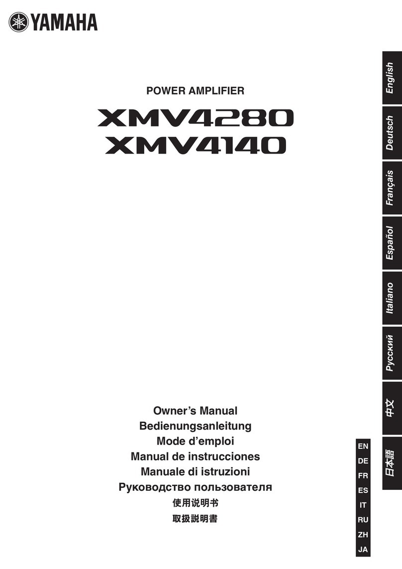
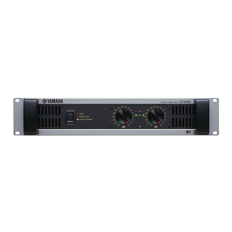
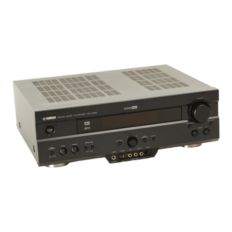
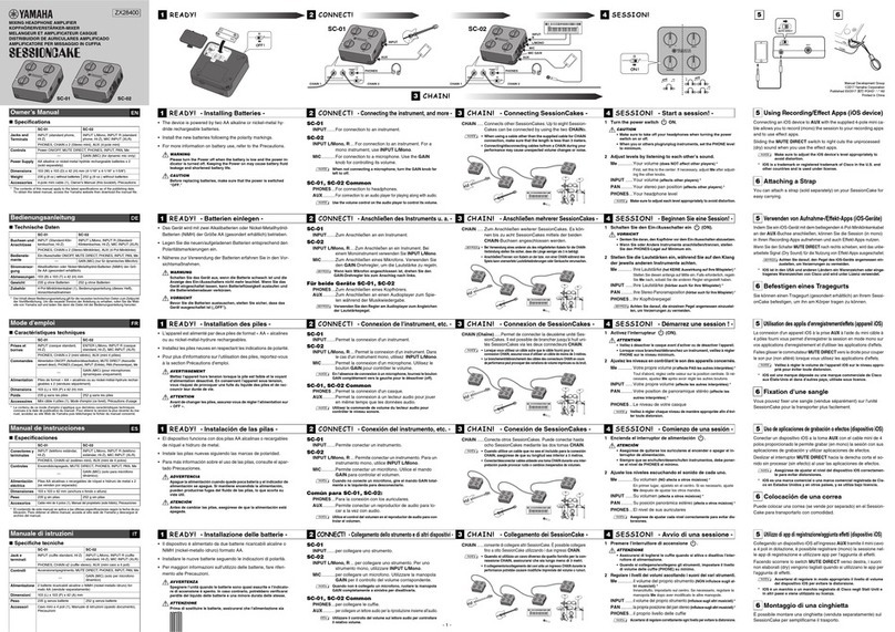
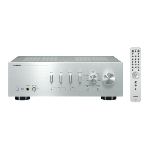
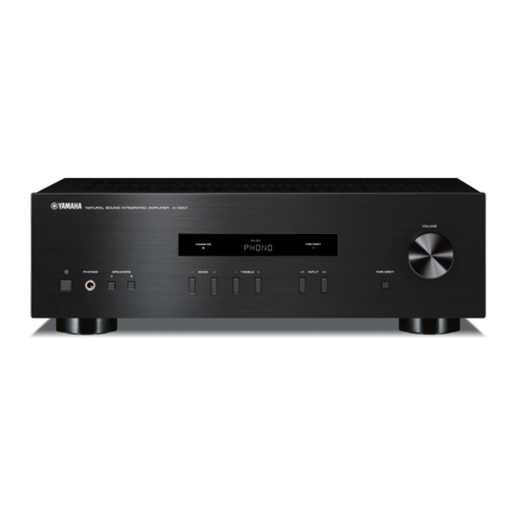
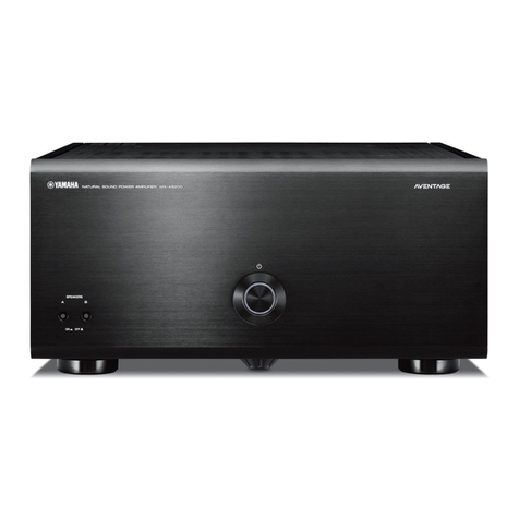
Yamaha A-S3000 User manual

P.O.Box 1, Hamamatsu, Japan
SERVICE MANUAL
INTEGRATED AMPLIFIER
A-S3000
101274
'13.10
■CONTENTS
TO SERVICE PERSONNEL ............................................2
FRONT PANELS .............................................................3
REAR PANELS ...........................................................4–6
REMOTE CONTROL PANEL ..........................................7
SPECIFICATIONS / 参考仕様 .....................................7–8
INTERNAL VIEW ............................................................9
SERVICE PRECAUTIONS / サービス時の注意事項 .......9
DISASSEMBLY PROCEDURES / 分解手順 ........... 10–20
UPDATING FIRMWARE /
ファームウェアのアップデート ............................21–25
SELF-DIAGNOSTIC FUNCTION /
ダイアグ(自己診断機能)
.....................................26–31
AMPLIFIER ADJUSTMENT / アンプ調整 ...............32–34
IC DATA ...................................................................35–40
PIN CONNECTION DIAGRAMS ...................................41
BLOCK DIAGRAMS ................................................ 42–43
WIRING DIAGRAMS ...............................................44–45
PRINTED CIRCUIT BOARDS .................................46–64
SCHEMATIC DIAGRAMS .......................................65–71
REPLACEMENT PARTS LIST ................................73–99
REMOTE CONTROL ...................................................100
IMPORTANT NOTICE
This manual has been provided for the use of authorized Yamaha Retailers and their service personnel.
It has been assumed that basic service procedures inherent to the industry, and more specifically Yamaha Products, are already known
and understood by the users, and have therefore not been restated.
WARNING: Failure to follow appropriate service and safety procedures when servicing this product may result in personal injury,
destruction of expensive components, and failure of the product to perform as specified. For these reasons, we advise
all Yamaha product owners that any service required should be performed by an authorized Yamaha Retailer or the
appointed service representative.
IMPORTANT:The presentation or sale of this manual to any individual or firm does not constitute authorization, certification or
recognition of any applicable technical capabilities, or establish a principle-agent relationship of any form.
The data provided is believed to be accurate and applicable to the unit(s) indicated on the cover. The research, engineering, and service
departments of Yamaha are continually striving to improve Yamaha products. Modifications are, therefore, inevitable and specifications
are subject to change without notice or obligation to retrofit. Should any discrepancy appear to exist, please contact the distributor's
Service Division.
WARNING: Static discharges can destroy expensive components. Discharge any static electricity your body may have
accumulated by grounding yourself to the ground buss in the unit (heavy gauge black wires connect to this buss).
IMPORTANT:Turn the unit OFF during disassembly and part replacement. Recheck all work before you apply power to the unit.
A-S3000

This product contains chemicals known to the State of California to cause cancer, or birth defects or other reproductive
harm.
DO NOT PLACE SOLDER, ELECTRICAL/ELECTRONIC OR PLASTIC COMPONENTS IN YOUR MOUTH FOR ANY REASON
WHATSOEVER!
Avoid prolonged, unprotected contact between solder and your skin! When soldering, do not inhale solder fumes or
expose eyes to solder/flux vapor!
If you come in contact with solder or components located inside the enclosure of this product, wash your hands before
handling food.
1. Critical Components Information
Components having special characteristics are marked ⚠and
must be replaced with parts having specifications equal to those
originally installed.
2. Leakage Current Measurement (For 120V Models Only)
When service has been completed, it is imperative to verify
that all exposed conductive surfaces are properly insulated
from supply circuits.
• Meter impedance should be equivalent to 1500 ohms shunted
by 0.15 F.
■TO SERVICE PERSONNEL
• Leakage current must not exceed 0.5mA.
• Be sure to test for leakage with the AC plug in both polarities.
WARNING: CHEMICAL CONTENT NOTICE!
WALL
OUTLET EQUIPMENT
UNDER TEST
AC LEAKAGE
TESTER OR
EQUIVALENT
INSULATING
TABLE
本機に搭載されているすべての基板およびハンダ付けに
よる接合部は無鉛ハンダでハンダ付けされています。
無鉛ハンダにはいくつかの種類がありますが、修理時に
は下記のような無鉛ハンダの使用を推奨します。
Sn+Ag+Cu(錫+銀+銅)
Sn+Cu(錫 + 銅)
Sn+Zn+Bi(錫 + 亜鉛 + ビスマス)
注意:
無鉛ハンダの融点温度は通常の鉛入りハンダに比べ 30 〜
40℃程度高くなっていますので、それぞれのハンダに合っ
たハンダごてをご使用ください。
All of the P.C.B.s installed in this unit and solder joints are
soldered using the lead free solder.
Among some types of lead free solder currently available,
it is recommended to use one of the following types for
the repair work.
• Sn + Ag + Cu (tin + silver + copper)
• Sn + Cu (tin + copper)
• Sn + Zn + Bi (tin + zinc + bismuth)
Caution:
As the melting point temperature of the lead free solder
is about 30°C to 40°C (50°F to 70°F) higher than that of
the lead solder, be sure to use a soldering iron suitable
to each solder.
About lead free solder / 無鉛ハンダについて
For U model
“CAUTION”
“F1: FOR CONTINUED PROTECTION AGAINST RISK OF FIRE, REPLACE ONLY WITH SAME TYPE 10A, 125V
FUSE.”
For C model
CAUTION
F1: REPLACE WITH SAME TYPE 10A, 125V FUSE.
ATTENTION
F1: UTILISER UN FUSIBLE DE RECHANGE DE MÉME TYPE DE 10A, 125V.
2
A-S3000
A-S3000

■FRONT PANELS
U, K, A, B, G, L, V, J models
T model
3
A-S3000
A-S3000

■REAR PANELS
U model
K model
T model
4
A-S3000
A-S3000

A model
B, G models
L model
5
A-S3000
A-S3000

V model
J model
6
A-S3000
A-S3000

■REMOTE CONTROL PANEL
RAS30
■SPECIFICATIONS /
参考仕様
■Audio Section / オーディオ部
Rated Output Power / 定格出力 (20 Hz to 20 kHz, 0.07 % THD)
8 ohms ......................................................................100 W + 100 W
4 ohms ......................................................................150 W + 150 W
Dynamic Power Per Channel / ダイナミックパワー (IHF)
8 ohms ......................................................................120 W + 120 W
6 ohms ......................................................................150 W + 150 W
4 ohms ......................................................................200 W + 200 W
2 ohms ......................................................................300 W + 300 W
Dynamic Headroom / ダイナミックヘッドルーム
8 ohms ..................................................................................0.79 dB
Maximum Power Per Channel (1 kHz, 0.7 % THD) [B, G models]
4 ohms ......................................................................170 W + 170 W
IEC Output Power (1 kHz, 0.02 % THD) [B, G models]
8 ohms ......................................................................105 W + 105 W
Maximum Effective Output Power / 実用最大出力 (JEITA)
(1 kHz, 10 % THD) [T, K, B, L, V, J models]
8 ohms ......................................................................130 W + 130 W
4 ohms ......................................................................210 W + 210 W
Power Bandwidth / 出力帯域幅 (0.1 % THD, 45 W / MAIN L/R drive)
8 ohms .....................................................................10 Hz to 60 kHz
Damping Factor / ダンピングファクタ (1 kHz)
8 ohms ........................................................................... 250 or more
Input Sensitivity/Input Impedance / 入力感度/入力インピーダンス
(1 kHz, 10 % THD)
PHONO (MC) ................................................. 100 µVrms / 50 ohms
(MM) ............................................. 2.5 mVrms / 47 k-ohms
CD, etc. ....................................................... 200 mVrms / 47 k-ohms
MAIN IN ............................................................. 1 Vrms / 47 k-ohms
BAL (balanced) 1, 2 ................................. 200 mVrms / 100 k-ohms
Maximum Power / 最大出力 (JEITA) (1 kHz, 10 % THD)
[T, L, V, J models]
8 ohms ......................................................................120 W + 120 W
4 ohms ......................................................................190 W + 190 W
Maximum Input Signal Voltage / 最大許容入力電圧 (1 kHz)
PHONO (0.003 % THD) (MC) ......................................... 2.3 mVrms
(MM) .......................................... 50 mVrms
CD, etc. (0.5 % THD) ..................................................... 2.80 mVrms
BAL (balanced) 1, 2 (0.5 % THD)
BYPASS ....................................................................... 2.80 mVrms
ATT. (-6 dB) ................................................................. 5.60 mVrms
Rated Output Voltage/Output Impedance /
定格出力電圧/出力インピーダンス
REC OUT ................................................... 200 mVrms / 1.5 k-ohms
PRE OUT ........................................................ 1.0 Vrms / 1.5 k-ohms
Headphone Jack Rated Output Power / ヘッドホン定格出力
(1 kHz, 32 ohms, 0.2 % THD)
CD, etc. ...................................................................70 mW + 70 mW
Frequency Response / 周波数特性
CD, etc. (5 Hz to 100 kHz) ............................................... +0 / -3 dB
(20 Hz to 20 kHz) ............................................ +0 / -0.3 dB
7
A-S3000
A-S3000

Deviations from RIAA Equalizer / RIAA イコライザ偏差
PHONO (MC) ...................................................................... ±0.5 dB
(MM) ..................................................................... ±0.5 dB
Total Harmonic Distortion / 全高調波歪率 (20 Hz to 20 kHz)
PHONO (MC) to REC OUT (1.2 Vrms) .................................. 0.02 %
(MM) to REC OUT (1.2 Vrms) ............................... 0.005 %
CD, etc. to SP OUT (50 W/8 ohms) ..................................... 0.025 %
BAL (balanced) 1, 2 to SP OUT (50 W/8 ohms) .................. 0.025 %
Signal to Noise Ratio / 信号対雑音比 (IHF-A network)
PHONO (MC) (Input shorted, 500 Vrms) ..............................85 dB
(MM) (Input shorted, 5 mVrms) .................................93 dB
CD, etc. (Input shorted, 200 mVrms) .....................................103 dB
Residual Noise / 残留ノイズ (IHF-A network)
........................................................................................... 33 Vrms
Channel Separation / チャンネルセパレーション (1 kHz/10 kHz)
PHONO (MC) (Input shorted, Vol: -30 dB)
...................................................... 66 dB or more / 77 dB or more
(MM) (Input shorted, Vol: -30 dB)
...................................................... 90 dB or more / 77 dB or more
CD, etc. (Input 5.1 k-ohms terminated)
...................................................... 74 dB or more / 54 dB or more
Tone Control Characteristics / トーンコントロール特性
Bass
Boost/Cut .............................................................. ±9 dB, at 50 Hz
Turnover frequency .............................................................350 Hz
Treble
Boost/Cut ............................................................ ±9 dB, at 20 kHz
Turnover frequency ............................................................ 3.5 kHz
■General / 総合
Power Supply / 電源電圧
U model .................................................................. AC 120 V, 60 Hz
T model ................................................................... AC 220 V, 50 Hz
K model .................................................................. AC 220 V, 60 Hz
A model .................................................................. AC 240 V, 50 Hz
B, G models ............................................................ AC 230 V, 50 Hz
L model ...................................................... AC 220–240 V, 50/60 Hz
V model ................................................................... AC 110 V, 60 Hz
J model .............................................................. AC 100 V, 50/60 Hz
Power Consumption / 消費電力
U model ......................................................................350 W/500 VA
T, K, A, B, G, L, V, J models .................................................... 350 W
Standby Power Consumption (reference data) /
待機時消費電力(参考値)
................................................................................................. 0.3 W
Maximum Power Consumption (1 kHz, 8 ohms, 10 % THD) [V model]
................................................................................................ 700 W
Dimensions (W x H x D) / 寸法(幅 × 高さ × 奥行き)
............................... 435 x 180 x 464 mm (17-1/8" x 7-1/8" x 18-1/4")
U .......................U.S.A. model
T .................... Chinese model
K ..................... Korean model
A ................Australian model
B ......................British model
G .................European model
L .................Singapore model
V ..................... Taiwan model
J .................. Japanese model
•DIMENSIONS /
寸法図
Unit: mm (inch)
単位:mm(インチ)
Weight / 質量
............................................................................. 24.6 kg (54.2 lbs.)
Finish / 仕上げ
K, A, G, L, V models ....................................Black/Dark brown color
U, T, A, B, G, L, V, J models..........................Black/Piano black color
K, A, G, L, V models .............................................. Silver/Birch color
U, T, A, B, G, L, V, J models..........................Silver/Piano black color
Color: Front and top panels / Side panel
Accessories / 付属品
Remote control ..............................................................................x 1
Battery (R03, AAA, UM-4) .............................................................x 2
Power cable (2.0 m) (U, T, K, A, B, G, L, V models) ....................x 1
(1.5 m) (J model) ....................................................x 1
*Specifications are subject to change without notice.
※ 参考仕様および外観は、製品の改良のため予告なく変更すること
があります。
435 (17-1/8")
Front view
Top view ø 45
319 (12-1/2") 54
(2-1/8")
48
(1-7/8")
421 (16-5/8")
464 (18-1/4")180 (7-1/8")
160 (6-1/4") 23
(7/8")
20
(3/4")
20
(3/4")
325 (12-3/4")
55
(2-1/8")
8
A-S3000
A-S3000
■INTERNAL VIEW
■SERVICE PRECAUTIONS / サービス時の注意事項
安全対策
・ この製品の内部には高電圧部分があり危険です。修理
の際は、絶縁性の手袋を使用するなどの安全対策を
行ってください。
・ 下記のコンデンサには電源を OFF にした後も電荷が残
り、高電圧が維持されており危険です。
修理作業前に放電用抵抗(5k Ω /10W)を下記の各コ
ンデンサの端子間に接続して放電してください。
放電所用時間は各々約 30 秒間です。
MAIN(3)P.C.B. の C317 〜 C320
詳しくは “PRINTEDCIRCUITBOARDS” を参照してくだ
さい。
Safety measures
• Some internal parts in this product contain high voltages
and are dangerous.
Be sure to take safety measures during servicing, such
as wearing insulating gloves.
• Note that the capacitors indicated below are dangerous
even after the power is turned off because an electric
charge remains and a high voltage continues to exist
there.
Before starting any repair work, connect a discharging
resistor (5 k-ohms/10 W) to the terminals of each
capacitor indicated below to discharge electricity.
The time required for discharging is about 30 seconds
per each.
C317 to C320 on MAIN (3) P.C.B.
For details, refer to “PRINTED CIRCUIT BOARDS”.
INPUT (2) P.C.B.
INPUT (1) P.C.B.
FRONT (16) P.C.B.
FUNCTION (2) P.C.B.
FRONT (15) P.C.B.
FUNCTION (1) P.C.B.
INPUT (3) P.C.B.
MAIN (1) P.C.B.
MAIN (3) P.C.B.
POWER TRANSFORMER
MAIN (2) P.C.B.
LED P.C.B.
FRONT (1) P.C.B.
METER UNIT
FRONT (2) P.C.B.
FRONT (3) P.C.B.
FRONT (5) P.C.B.
FRONT (6) P.C.B.
FRONT (4) P.C.B.
FRONT (7) P.C.B.
FRONT (8) P.C.B.
FRONT (9) P.C.B.
FRONT (10) P.C.B.
FRONT (11) P.C.B.
FRONT (12) P.C.B.
FRONT (14) P.C.B.
FRONT (13) P.C.B.
Top view
Front view
Rear view 1
2
3
4
5
6
7
8
9
10
11
12
13
14
15
16
17
18
19
20
21
22
23
24
25
26
27
1
6
12 13
2
7
4
10
17182122232426 19
8
16202527
911
35
1514
9
A-S3000
A-S3000

■DISASSEMBLY PROCEDURES / 分解手順
Fig. 1
(Remove parts in the order as numbered.)
Disconnect the power cable from the AC outlet.
1. Removal of Top Panel
a. Remove 3 screws (①). (Fig. 1)
b. Remove the top panel. (Fig. 1)
2. Removal of Side Panel L and Side Panel R
a. Remove 3 screws (②). (Fig. 1)
b. Lift the side panel L a little, release hooks at 3 locations
and then remove the side panel L. (Fig. 1)
c. Remove 3 screws (③). (Fig. 1)
d. Lift the side panel R a little, release hooks at 3 locations
and remove the side panel R. (Fig. 1)
(番号順に部品を外してください。)
AC 電源コンセントから、電源コードを抜いてください。
1. トップパネルの外し方
a. ①ネジ 3 本を外します。(Fig.1)
b. トップパネルを外します。(Fig.1)
2. サイドパネル L、サイドパネル R の外し方
a. ②のネジ 3 本を外します。(Fig.1)
b. サイドパネル L を少し持ち上げ、3 ヶ所のフックを外
し、サイドパネル L を外します。(Fig.1)
c. ③のネジ 3 本を外します。(Fig.1)
d. サイドパネル R を少し持ち上げ、3 ヶ所のフックを外
し、サイドパネル R を外します。(Fig.1)
Top panel
トップ パ ネ ル
Side panel L
サイドパネル L
Side panel R
サイドパネル R
Hook
フック
Hook
フック ①
②
②
③
③
10
A-S3000
A-S3000

Front panel unit
フロントパネルユ ニット
CB406
CB403
CB401 CB410
CB405
FRONT (12) P.C.B.
FRONT (14) P.C.B.
FRONT (1) P.C.B.
Hook
フック
Hook
フック
④
④
VOLUME knob unit
VOLUME つまみ
INPUT knob unit
INPUT つまみ
TONE CONTROL knob unit
TONECONTROL つまみ
3. Removal of Front Panel Unit
a. Remove 5 screws (④). (Fig. 2)
b. Remove CB401, CB403, CB405, CB406 and CB410.
(Fig. 2)
c. Remove the front panel unit. (Fig. 2)
3. フロントパネルユニットの外し方
a. ④のネジ 5 本を外します。(Fig.2)
b. CB401、CB403、CB405、CB406、CB410 を外します。
(Fig.2)
c. フロントパネルユニットを外します。(Fig.2)
Fig. 2
11
A-S3000
A-S3000

Fig. 3
VOLUME knob unit
VOLUME つまみ
VOLUME knob unit
VOLUME つまみ
“VOLUME MAX.” position
VOLUMEMAX.位置
“VOLUME MIN.” position
VOLUMEMIN.位置
Position about -180° from “VOLUME MAX”
position
VOLUMEMAX.の位置から約 -180°の位置
Install/remove the lock set screw at this position
on the back of the front panel.
フロントパネル裏側のこの箇所で止めネジの
取り外し/取り付けを行います。
Lock set screw
止めネジ
Lock set screw
止めネジ Side view
VR401
Cut
カット位置
0.5–0.75 mm
Pointer
指標
Pointer
指標
Front panel
Lock set screw
止めネジ Hexagonal screwdriver
6 角ドライバー
2mm
●When installing the knob unit
*Prepare a hexagonal screwdriver (2 mm) for
installation of knob unit.
When installing the VOLUME knob unit:
a. Turn the VOLUME (VR401) clockwise fully. (Fig. 3)
b. Match the pointer in the VOLUME knob unit with
the “VOLUME MAX.” position and install it in that
state. (Fig. 3)
*At this time, do not tighten the lock set screw.
c. Keep about 0.5 mm to 0.75 mm clearance from
the front panel to VOLUME knob unit. (Fig. 3)
d. Tighten the lock set screw. (Fig. 3)
e. Match the pointer in the VOLUME knob unit with
the position about -180° from the “VOLUME MAX”
position. (Fig. 3)
f. Tighten the lock set screw. (Fig. 3)
g. After installation, perform following checks.
• Turn the VOLUME knob unit both directions to
check that it does not rub against the front panel.
• Turn the VOLUME knob unit clockwise fully and
check that the pointer in it matches with the
“VOLUME MAX.” position.
• Turn the VOLUME knob unit counterclockwise
fully and check that the pointer in it matches
with the “VOLUME MIN.” position.
● つまみを取り付ける場合
※ つまみを取り付ける場合、6 角ドライバー(2
mm)を準備します。
VOLUME つまみを取り付ける場合:
a. VOLUME(VR401)を右いっぱいに回します。(Fig.3)
b. VOLUME つまみの指標を “VOLUMEMAX.” の位置
に合わせ、取り付けます。(Fig.3)
※ このとき、まだ止めネジは締めません。
c. フロントパネルから VOLUME つまみまで 0.5 〜
0.75mm 程度隙間をあけます。(Fig.3)
d. 止めネジを締めます。(Fig.3)
e. VOLUME つまみの指標を “VOLUMEMAX.” の位置
から約 -180°の位置に合わせます。(Fig.3)
f. 止めネジを締めます。(Fig.3)
g. 取り付け後、次の動作を確認します。
・ VOLUME つまみを左右に回し、フロントパネル
に擦っていないか?
・ VOLUME つまみを右いっぱいに回し、VOLUME
つまみの指標が “VOLUMEMAX.” の位置に合う
か?
・ VOLUME つまみを左いっぱいに回し、VOLUME
つまみの指標が “VOLUMEMIN.” の位置に合う
か?
12
A-S3000
A-S3000

Fig. 4
When installing the INPUT knob unit:
a. Turn the INPUT (SW403) so that the cut in it comes
at the under. (Fig. 4)
b. Install the INPUT knob unit with its lock set screw
positioned at the under. (Fig. 4)
*At this time, do not tighten the lock set screw.
c. Keep about 0.5 mm to 0.75 mm clearance from
the front panel to INPUT knob unit. (Fig. 4)
d. Match the lock set screw position with the cut in
INPUT (SW403) and tighten the lock set screw.
(Fig. 4)
e. Turn the INPUT knob unit by 180 degrees (6 clicks)
and tighten another lock set screw. (Fig. 4)
f. After installation, perform following checks.
• Turn the INPUT knob unit in both directions to
check that it does not rub against the front panel.
INPUT つまみを取り付ける場合:
a. INPUT(SW403)のカット位置が下になるよう回
します。(Fig.4)
b. INPUT つまみの止めネジ位置を下にして取り付け
ます。(Fig.4)
※ このとき、止めネジは締めません。
c. フロントパネルからINPUT つまみまで0.5〜
0.75mm 程度隙間をあけます。(Fig.4)
d. INPUT(SW403)のカット位置に止めネジ位置を
合わせ、止めネジを締めます。(Fig.4)
e. INPUT つまみを 180°回転(6 クリック)させ、も
う 1 つの止めネジを締めます。(Fig.4)
f. 取り付け後、次の動作を確認します。
・ INPUT つまみを左右に回し、フロントパネルに
擦っていないか?
Lock set screw
止めネジ
Bottom view
Lock set screw
止めネジ
SW403
Cut
カット位置
Front panel
Front panel
0.5–0.75 mm
INPUT knob unit
INPUT つまみ
Install/remove the lock set screw at this position
on the back of the front panel.
フロントパネル裏側のこの箇所で止めネジの
取り外し/取り付けを行います。
13
A-S3000
A-S3000

Fig. 5
When installing the BASS, TREBLE and BALANCE
knob units:
*Use the same installation procedure for BASS,
TREBLE and BALANCE knob units.
Described here is installation of BALANCE knob
unit as an example.
a. Turn the BALANCE (VR403) in both directions and
set it to the center position. (Fig. 5)
*VR403 stops at the center position when it is
turned in both directions.
b. Match the pointer in the BALANCE knob unit with
the center position of BALANCE and install it in
that state. (Fig. 5)
*At this time, do not tighten the lock set screw.
c. Keep about 0.5 mm to 0.75 mm clearance from
the front panel to BALANCE knob unit. (Fig. 5)
d. Tighten the lock set screw of the BALANCE knob
unit. (Fig. 5)
e. After installation, perform following checks.
• Turn the BALANCE knob unit in both directions
to check that it does not rub against the front
panel.
• Turn the BALANCE knob unit counterclockwise
fully and check that the pointer in it matches with
the “BALANCE L” position.
• Turn the BALANCE knob unit clockwise fully
and check that the pointer in it matches with the
“BALANCE R” position.
BASS、TREBLE、BALANCE つまみを取り付ける場合:
※ BASS、TREBLE、BALANCE つまみの取り付け方法
はすべて同じです。
例として BALANCE つまみの取り付け方法を記載
します。
a. BALANCE(VR403)を左右に回し、中央の位置に
合わせます。(Fig.5)
※ 左右に回すと、中央の位置で一度止まります。
b. BALANCE つまみの指標を BALANCE 中央の位置に
合わせ、取り付けます。(Fig.5)
※ このとき、まだ止めネジは締めません。
c. フロントパネルから BALANCE つまみまで 0.5 〜
0.75mm 程度隙間をあけます。(Fig.5)
d. BALANCE つまみの止めネジを締めます。(Fig.5)
e. 取り付け後、次の動作を確認します。
・ BALANCE つまみを左右に回し、フロントパネ
ルに擦っていないか?
・ BALANCE つまみを左いっぱいに回し、BALANCE
つまみの指標が “BALANCEL” の位置に合うか?
・ BALANCE つまみを右いっぱいに回し、BALANCE
つまみの指標が “BALANCER” の位置に合うか?
“BALANCE” knob unit
BALANCEつまみ
Center position of “BALANCE” knob unit
BALANCEつまみの中央位置
Lock set screw
止めネジ
Bottom view
VR403
0.5–0.75 mm
Front panel
Front panel
Pointer
指標
Install/remove the lock set screw at this position
on the front of the front panel.
フロントパネル表側のこの箇所で止めネジの
取り外し/取り付けを行います。
14
A-S3000
A-S3000

4. Removal of Sub-chassis
a. Remove 4 screws (⑤). (Fig. 6)
b. Remove the support top L and support top R. (Fig. 6)
c. Remove 4 screws (⑥). (Fig. 6)
d. Remove the sub-chassis. (Fig. 6)
4. サブシャーシの外し方
a. ⑤のネジ 4 本を外します。(Fig.6)
b. サポートトップ L とサポートトップ R を外します。
(Fig.6)
c. ⑥のネジ 4 本を外します。(Fig.6)
d. サブシャーシを外します。(Fig.6)
Fig. 6
Sub-chassis
サブシャーシ
Support top (R)
サポートトップ(R)
Support top (L)
サポートトップ(L)
⑤
⑤
⑤
⑤
⑥
⑥
15
A-S3000
A-S3000

When checking the P.C.B.:
• Put a rubber sheet and cloth under the equipment.
Then place this unit on the cloth and check it. (Fig. 7)
• Connect the front panel unit to the chassis with a
ground lead or the like. (Fig. 7)
• Reconnect all cables (connectors) that have been
disconnected.
• When connecting the flexible flat cable, be careful with
polarity.
P.C.B. をチェックをする場合には:
・ ゴムシートと布を敷き、その上に本機を置いてチェッ
クします。(Fig.7)
・ フロントパネルユニットをリード線等でシャーシに
接続してください。(Fig.7)
・ 外したケーブル(コネクター)をすべて接続します。
・ フラットケーブルを接続する際、極性に注意してく
ださい。
Fig. 7
Chassis
シャーシ
Front panel unit
フロントパネルユ ニット
Ground lead
アース線
Rubber sheet and cloth
ゴムシートと布
16
A-S3000
A-S3000

5. Removal of Heatsink Unit L, Heatsink Unit R
and Power Unit
a. Remove 8 screws (⑦) and 16 screws (⑧). (Fig. 8)
b. Remove 5 screws (⑨) and disconnect 5 cables.
(Fig. 8)
c. Remove 2 screws (⑩) and then remove 2 push rivets.
(Fig. 8)
d. Remove CB1, CB101, CB201, CB305, CB306, CB502
and CB505. (Fig. 8)
e. Remove the heatsink unit L and heatsink unit R
together with the power unit. (Fig. 8)
5. ヒートシンクユニット L、ヒートシンクユニット
R、パワーユニットの外し方
a. ⑦のネジ 8 本、⑧のネジ 16 本を外します。(Fig.8)
b. ⑨のネジ 5 本を外し、ケーブル 5 本を外します。
(Fig.8)
c. ⑩のネジ 2 本とプッシュリベット 2 個を外します。
(Fig.8)
d. CB1、CB101、CB201、CB305、CB306、CB502、CB505
を外します。(Fig.8)
e. ヒートシンクユニット L、ヒートシンクユニット R と
パワーユニットを一緒に外します。(Fig.8)
Power unit
パワーユニットHeatsink unit R
ヒートシンクユニットR
Heatsink unit L
ヒートシンクユニットL
CB201
CB306
CB305
W413
W414
CB101
CB505
CB1
CB502
MAIN (3) P.C.B.
FUNCTION (1) P.C.B.
MAIN (2) P.C.B.
MAIN (1) P.C.B.
Push rivet
プッシュリベット
W416
W52
W415
⑦
⑦
⑩
⑦
⑦
⑧
⑧
⑧
⑧
⑧
⑧
⑧
⑨
⑨
⑨
⑨⑨
Fig. 8
17
A-S3000
A-S3000

g. Remove 10 screws (⑪). (Fig. 9)
h. Remove the front frame. (Fig. 9)
i. Remove 10 screws (⑫). (Fig. 9)
j. Remove the rear frame. (Fig. 9)
k. Remove 4 screws (⑬). (Fig. 9)
l. Remove CB205, CB206, CB304 and CB308. (Fig. 9)
m. Remove the heatsink unit L together with the MAIN (2)
P.C.B. (Fig. 9)
n. Remove 4 screws (⑭). (Fig. 9)
o. Remove CB303. (Fig. 9)
p. Remove the heatsink unit R together with the MAIN (1)
P.C.B. (Fig. 9)
g. ⑪のネジ 10 本を外します。(Fig.9)
h. フロントフレームを外します。(Fig.9)
i. ⑫のネジ 10 本を外します。(Fig.9)
j. リアフレームを外します。(Fig.9)
k. ⑬のネジ 4 本を外します。(Fig.9)
l. CB205、CB206、CB304、CB308 を外します。(Fig.9)
m. ヒートシンクユニット L と MAIN(2)P.C.B. を一緒に
外します。(Fig.9)
n. ⑭のネジ 4 本を外します。(Fig.9)
o. CB303 を外します。(Fig.9)
p. ヒートシンクユニット R と MAIN(1)P.C.B. を一緒に
外します。(Fig.9)
Fig. 9
Heatsink unit L
ヒートシンクユニットL
Rear frame
リアフレーム
Front frame
フロントフレーム
Power unit
パワーユニット
MAIN (3) P.C.B.
Heatsink unit R
ヒートシンクユニットR
⑫
⑫
⑫
⑫
⑫
⑫
⑫
⑭
⑪
⑪
⑬
⑪
⑪
⑪
⑪⑪
MAIN (2) P.C.B.
MAIN (1) P.C.B.
CB308
CB303
CB304
CB206
CB205
18
A-S3000
A-S3000
Power unit
パワーユニット
Heatsink unit R
ヒートシンクユニットR
Heatsink unit L
ヒートシンクユニットL
Rubber sheet and cloth
ゴムシートと布 Fig. 11
Fig. 10
When checking the P.C.B.:
• Put the rubber sheet and cloth over this unit. Then
place the P.C.B. slantingly on the cloth and check it.
(Fig. 10)
• Connect the front panel unit, heatsink unit L and
heatsink unit R to the chassis with a ground lead or
the like. (Fig. 10)
• Reconnect all cables (connectors) that have been
disconnected.
• When connecting the flexible flat cable, be careful with
polarity.
• It is also possible to check the power unit, heatsink
unit L and heatsink unit R from the bottom. (Fig. 11)
P.C.B. をチェックをする場合には:
・ 本機の上にゴムシートと布を敷き、その上に P.C.B. を
斜めに置いてチェックします。(Fig.10)
・ フロントパネルユニットとヒートシンクユニット L、
ヒートシンクユニット R をリード線等でシャーシに
接続してください。(Fig.10)
・ 外したケーブル(コネクター)をすべて接続します。
・ フラットケーブルを接続する際、極性に注意してく
ださい。
・ パワーユニット、ヒートシンクユニット L、ヒート
シンクユニット R は底面からチェックすることもで
きます。(Fig.11)
Rubber sheet and cloth
ゴムシートと布 Front panel unit
フロントパネルユ ニット
Ground lead
アース線
Ground lead
アース線
Heatsink unit L
ヒートシンクユニットL
Power unit
パワーユニット
Heatsink unit R
ヒートシンクユニットR
19
A-S3000
A-S3000
⑯
⑯
⑳
CB803
CB801
CB802
Shield case (LOW)
シールドケース(LOW)
⑲INPUT (2) P.C.B.
Shield case (UP)
シールドケース(UP)
W712
INPUT (1) P.C.B.
P.C.B. support
P.C.B. サポート
㉑
Board-to-board connectors
基板対基板コネクター
CB512
FUNCTION (1) P.C.B.
CB501
CB716
CB510
CB506
FUNCTION (2) P.C.B.
CB903
CB902
CB905
Board-to-board connectors
基板対基板コネクター
CB904
CB908
CB906
CB907
INPUT (3) P.C.B.
CB909
Fig. 13
Rear view
㉓
⑮⑱ ⑰⑮
㉒
Fig. 12
6. Removal of INPUT (2) P.C.B.
a. Remove 2 screws (⑮). (Fig. 12)
b. Remove 4 screws (⑯). (Fig. 13)
c. Remove CB801, CB802 and CB803. (Fig. 13)
d. Remove the shield case together with the INPUT (2)
P.C.B. (Fig. 13)
7. Removal of INPUT (1) P.C.B.
a. Remove 7 screws (⑰) and 8 screws (⑱). (Fig. 12)
b. Remove 3 screws (⑲) and then remove the P.C.B.
support. (Fig. 13)
c. Remove screw (⑳) and disconnect cable. (Fig. 13)
d. Remove 3 screws (㉑). (Fig. 13)
e. Remove CB902, CB903 and CB905. (Fig. 13)
f. Remove the INPUT (1) P.C.B. which is connected
directly to the INPUT (3) P.C.B. with board-to-board
connectors. (Fig. 13)
8. Removal of FUNCTION (1) and (2) P.C.B.
a. Remove 7 screws (⑰) and 8 screws (⑱). (Fig. 12)
b. Remove CB501 and CB506. (Fig. 13)
c. Remove the FUNCTION (1) and (2) P.C.B.s which is
connected directly to the INPUT (3) P.C.B. with board-
to-board connectors. (Fig. 13)
6. INPUT(2)P.C.B. の外し方
a. ⑮のネジ 2 本を外します。(Fig.12)
b. ⑯のネジ 4 本を外します。(Fig.13)
c. CB801、CB802、CB803 を外します。(Fig.13)
d. シールドケースと一緒に INPUT(2)P.C.B. を外します。
(Fig.13)
7. INPUT(1)P.C.B. の外し方
a. ⑰のネジ 7 本、⑱のネジ 8 本を外します。(Fig.12)
b. ⑲のネジ 3 本を外し、P.C.B. サポートを外します。
(Fig.13)
c. ⑳のネジ 1 本を外し、ケーブル 1 本を外します。
(Fig.13)
d. ㉑のネジ 3 本を外します。(Fig.13)
e. CB902、CB903、CB905 を外します。(Fig.13)
f. INPUT(1)P.C.B. を外します。(Fig.13)
ただし、INPUT(1)P.C.B. は INPUT(3)P.C.B. に基板
対基板コネクターで直接接続されています。(Fig.13)
8. FUNCTION(1)、(2)P.C.B. の外し方
a. ㉒のネジ 3 本、㉓のネジ 5 本を外します。(Fig.12)
b. CB501、CB506 を外します。(Fig.13)
c. FUNCTION(1)、(2)P.C.B. を外します。(Fig.13)
ただし、FUNCTION(1)と(2)P.C.B. は INPUT(3)P.C.B. に
基板対基板コネクターで直接接続されています。
(Fig.13)
20
A-S3000
A-S3000
Other manuals for A-S3000
3
Table of contents
Other Yamaha Amplifier manuals

Yamaha
Yamaha A-S2000 - Amplifier User manual

Yamaha
Yamaha DSP-AX620 User manual

Yamaha
Yamaha A-S501 User manual

Yamaha
Yamaha MusicCAST MCX-CA15 User manual

Yamaha
Yamaha P1250 User manual

Yamaha
Yamaha T-100 Guide

Yamaha
Yamaha AV-90PY User manual

Yamaha
Yamaha BBT 500H User manual

Yamaha
Yamaha CA-610 User manual

Yamaha
Yamaha P1600 User manual

Yamaha
Yamaha PX8 User manual

Yamaha
Yamaha A-520 User manual

Yamaha
Yamaha Electone C-60 User manual

Yamaha
Yamaha AX-500U User manual

Yamaha
Yamaha XS250 User manual

Yamaha
Yamaha B-6 User manual

Yamaha
Yamaha P2500S User manual

Yamaha
Yamaha E580 User manual

Yamaha
Yamaha DSP-A492 User manual

Yamaha
Yamaha AVC-70 User manual