Yamaha P1600 User manual

POWER AMPLIFIER
Owner's Manual
Mode d'emploi
Bedienungsanleitung
Manual de instrucciónes
TEMP
PROTECTION
POWER
ON OFF
AB
CLIP
SIGNAL
–dB∞0∞0
40
30
20 15
10
3
6
25
40
30
20 15
10
3
6
25
EEEngine
M

Introduction
English
Thank you for purchasing a Yamaha P4500/3200/1600 series power amplifier.
This series of audio amps was developed from Yamaha's wealth of experience in building PA
equipment and its tradition of careful attention to every detail of circuit design. These amps
featurehighpowerandsuperbqualitytogetherwithsuperiorreliabilityandstability,guarantee-
ing the highest possible audio performance.
Main features of the P4500/P3200/P1600 series
• Threetypesofinputjack(balancedXLRtypeconnectors,balancedphonejacks,andbarrier
strip), and five-way binding post output jacks are provided, allowing use in a wide variety
of situations including installed applications.
• Three operating modes are provided: STEREO mode in which CHANNEL A and B operate
independently,PARALLELmodeinwhichamonosourceisoutput bytwoampsystems,and
BRIDGE mode in which the unit operates as a single high-power amplifier.
• A SIGNAL indicator and CLIP indicator is provided for each channel.
• The PROTECTION indicator shows the status of protective circuitry such as power-on/off
protection,output muting,and theDC detectioncircuit. TheTEMP indicatorwarns ofheat
sink overheating.
• Variable-speedlow-noisefan(s)ensureshighreliabilityevenunderdemandingconditions.
This owner's manual covers the three models P4500, P3200 and P1600. In order to take full
advantageofyourpowerampandenjoylongandtrouble-freeoperation,pleasereadthisowner's
manual carefully before use.
IMPORTANT NOTICE FOR
THE UNITED KINGDOM
Connecting the Plug and Cord
WARNING: THIS APPARATUS MUST BE EARTHED
IMPORTANT: The wires in this mains lead are coloured in accordance with
the following code:
GREEN-AND-YELLOW : EARTH
BLUE : NEUTRAL
BROWN : LIVE
As the colours of the wires in the mains lead of this apparatus may not
correspond with the coloured markings identifying the terminals in your
plug, proceed as follows:
The wire which is coloured GREEN and YELLOW must be connected to
the terminal in the plug which is marked by the letter E or by the safety earth
symbol or coloured GREEN and YELLOW.
The wire which is coloured BLUE must be connected to the terminal which
is marked with the letter N or coloured BLACK.
The wire which is coloured BROWN must be connected to the terminal
which is marked with the letter L or coloured RED.
* This applies only to products distributed by YAMAHA KEMBLE
MUSIC (U.K.) LTD.

Precautions
1. Avoid excessive heat, humidity, dust and vibration.
Keeptheunitawayfromlocationswhereitislikelytobe
exposed to high temperatures or humidity — such as
near radiators, stoves, etc. Also avoid locations which
are subject to excessive dust accumulation or vibration
which could cause mechanical damage.
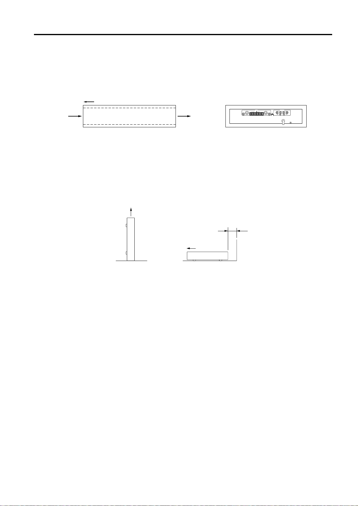
2. Ventilation
Allow a distance of 10 cm between the unit and the wall
so that heat generated from the unit will be released
effectively. Also, allow enough space between the unit
andotherdevices.Ifyoumounttheunitinanaudiorack,
keep a space of 10 cm on the top panel, and a space of
1 cmtothesidepanel.Removetherearpaneloftherack
oropenaventhole.Ifheatreleaseisinadequate,theunit
will retain heat inside the unit, which may cause a fire.
3. Avoid physical shocks.
Strong physical shocks to the unit can cause damage.
Handle it with care.
4. Do not open the case or attempt repairs or modifica-
tions yourself.
This product contains no user-serviceable parts. Refer
all maintenance to qualified Yamaha service personnel.
Opening the case and/or tampering with the internal
circuitry will void the warranty.
5. Make sure power is off before making or removing
connections.
Always turn the power OFF prior to connecting or
disconnecting cables. This is important to prevent dam-
age to the unit itself as well as other connected equip-
ment.
6. Handle cables carefully.
Alwaysplugandunplugcables—includingtheACcord
— by gripping the connector, not the cord.
7. Clean with a soft dry cloth.
Never use solvents such as benzine or thinner to clean
the unit. Wipe clean with a soft, dry cloth.
8. Always use the correct power supply.
Makesurethatthepowersupplyvoltagespecifiedonthe
rear panel matches your local AC mains supply. Also
make sure that the AC mains supply can deliver more
thanenoughcurrenttohandleallequipmentusedinyour
system.
Contents
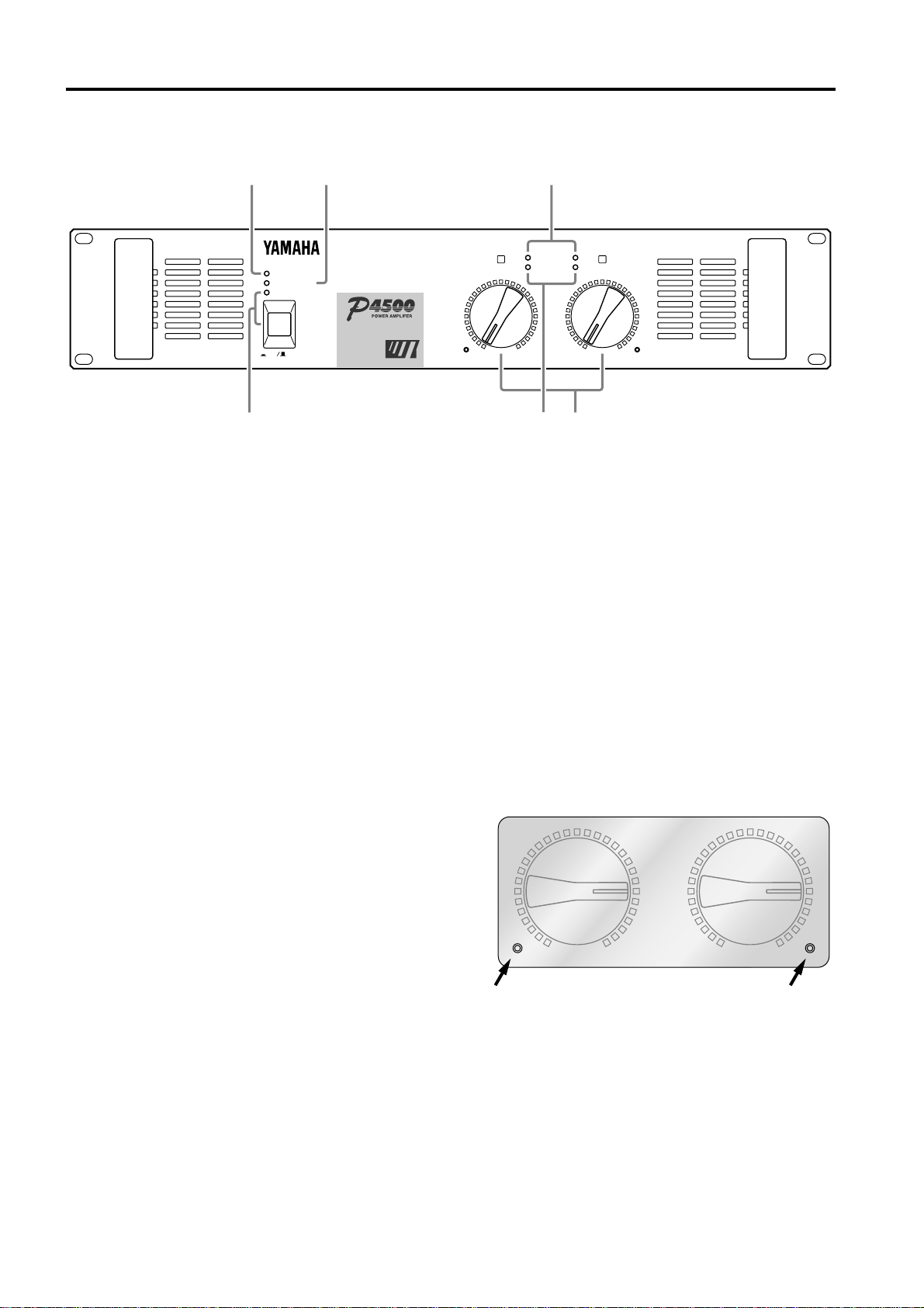
Controls and Functions ............................................................. 2
Front Panel........................................................................... 2
Rear Panel ........................................................................... 3
Modes: STEREO/PARALLEL/BRIDGE................................ 4
SPEAKER IMPEDANCE...................................................... 4
Caution for Speaker Connection ............................................... 5
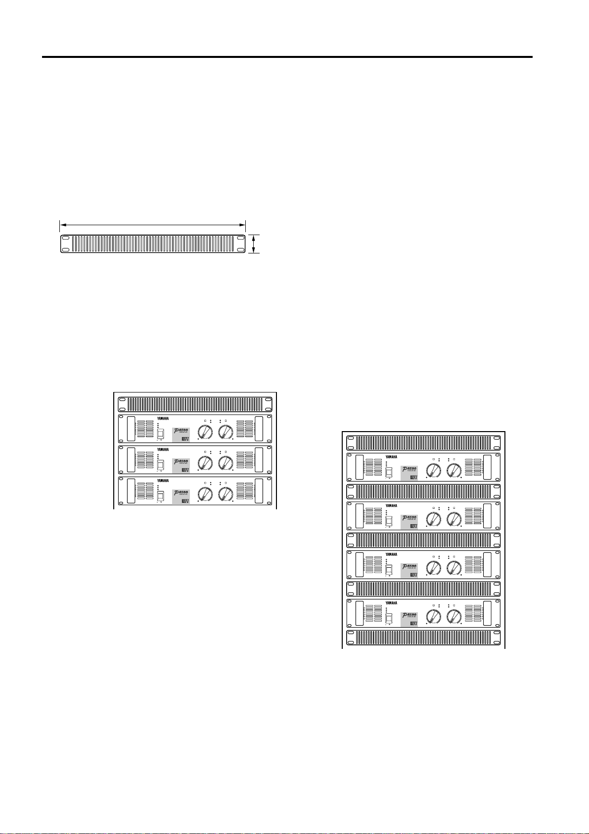
Rack Mounting .......................................................................... 6
Mounting in an EIA standard rack ....................................... 6
Mounting four or fewer amps in an open-backed rack......... 6
Mounting five or more amps, or when (even with four or
fewer units) the back of the rack cannot be left open.......... 6
Portable Rack Mounting ...................................................... 7
Positioning the Housed Amplifier......................................... 7
Specifications ............................................................................ 8
General Specifications......................................................... 8
Block Diagram...................................................................... 9
Dimensions .......................................................................... 9
Performance Graphs.......................................................... 10
Troubleshooting ...................................................................... 10

2
Controls and Functions
■Front Panel
TEMP
PROTECTION
POWER
ON OFF
AB
CLIP
SIGNAL
61
23 4
5
–dB∞0∞0
40
30
20 15
10
3
6
25
40
30
20 15
10
3
6
25
EEEngine
1POWER switch and indicator
This is the main POWER switch. Press to power ON the
amplifier. Press again to power OFF. The POWER
indicator lights up when the amplifier is powered ON.
2TEMP indicator
When the temperature of the heat sink exceeds 85
degrees Celsius, this indicator will light red.
3PROTECTION indicator
This red LED indicator lights up for approximately 3
seconds when the amplifier is powered ON, indicating
that the soft-start protection system is working. No
sound is output during soft-start up. If one of the protec-
tion systems is activated during normal use, this indica-
tor lights up and no sound is output. The speaker system
isactuallydisconnectedfromtheamplifieroutputswhen
this indicator lights up. The protection systems are
activated when overheating occurs or a DC voltage is
present at the amplifier outputs. If the problem is cor-
rected, the protection systems deactivate automatically,
thisindicatorgoesout,andnormalamplifieroperationis
resumed.
4CLIP indicators
These red LED indicators light up when the respective
channel’s output signal distortion exceeds 1% (i.e. clip-
ping).Output signal clipping is usually due to excessive
input signal levels.
5SIGNAL indicators
ThesegreenLEDindicatorslightupwhentherespective
channel’s output signal exceeds 2 Vrms. This is equiva-
lent to 1/2 watt into 8Ω, 1 W into 4Ω.
6Volume controls
These volume controls allow you to adjust the volume
level in 31 steps in the range between –∞dB and 0 dB.
To fix the volume setting by protecting the controls,
install the included security cover over the controls and
tighten the screws in the holes as shown below.
–dB∞0∞0
40
30
20 15
10
3
6
25
40
30
20 15
10
3
6
25

3
■Rear Panel
INPUT SPEAKERS
CHANNEL B CHANNEL A CHANNEL B CHANNEL A
GG
(BRIDGE)
(PARALLEL)
BRIDGE
STEREO PARALLEL
STEREO
BRIDGE
MAX. OUTPUT 450W/4Ω(STEREO)
MAX. OUTPUT 900W/8Ω(BRIDGE)
(STEREO)
4-8Ω/SP
(BRIDGE)
8-16Ω/SP
3214
3SPEAKERS terminals
For polarity in each mode, refer to the following dia-
gram.
• STEREO, PARALLEL mode
SPEAKERS
CHANNEL B CHANNEL A
STEREO
BRIDGE
• BRIDGE mode
SPEAKERS
CHANNEL B CHANNEL A
STEREO
BRIDGE
InBRIDGE mode, the (-)jacks of CHANNELS A and
B are not used.
The minimum impedance for the connected speaker
system is specified in “Speaker Impedance”on page 4.
4GND terminals
This is the grounding screw terminal. If hum or noise
occurs, ground (earth) the unit via this jack, or try
connecting it to the chassis of the mixer or preamp, etc.
1INPUT terminals (CHANNEL A, B)
Three types of balanced terminals for channels A and B
are provided.
Channel A input terminal is used in Bridge and Parallel
mode.
•XLR-3-31 type connector
Theyarewiredpin1–ground,pin2–hot(
+
),andpin3cold
(
-
).
1
23
Cold
GroundHot
•Phone jack
Theyare wired tip–hot(+),ring–cold (-), and sleeve–
ground.
Ring
Sleeve Tip
•Barrier strip
Hot (+), Cold (-) and Ground (G).
2STEREO/BRIDGE/PARALLEL switch
This slide switch is used to set the amplifier operating
mode: STEREO, BRIDGE or PARALLEL.
For details on the functionality of each mode, refer to
“Modes”on page 4.

4
■Modes: STEREO/PARALLEL/BRIDGE
BRIDGE mode
In this mode, the CHANNEL A input signal will be
output from the BRIDGE output jacks. In this case, use
thefrontpanel(channel)
A
volumecontroltoadjustthe
volume.
■SPEAKER IMPEDANCE
InSTEREOandPARALLELmodes,theminimumload
(=speaker)impedance is 4Ω.In BRIDGE modeit is 8Ω.
Make sure that the impedance does not fall below this
specified impedance.
STEREO mode connections
SPEAKERS
CHANNEL B CHANNEL A
BRIDGE
STEREO PARALLEL
STEREO
BRIDGE
MAX. OUTPUT 450W/4Ω(STEREO)
MAX. OUTPUT 900W/8Ω(BRIDGE)
–+
–+
Set to STEREO
Speaker S
y
stem
4Ωmin. 4Ωmin.
PARALLEL mode connections
SPEAKERS
CHANNEL B CHANNEL A
BRIDGE
STEREO PARALLEL
STEREO
BRIDGE
MAX. OUTPUT 450W/4Ω(STEREO)
MAX. OUTPUT 900W/8Ω(BRIDGE)
–+
–+
Set to PARALLEL
Speaker S
y
stem
4Ωmin. 4Ωmin.
BRIDGE mode connections
SPEAKERS
CHANNEL B CHANNEL A
BRIDGE
STEREO PARALLEL
STEREO
BRIDGE
MAX. OUTPUT 450W/4Ω(STEREO)
MAX. OUTPUT 900W/8Ω(BRIDGE)
–+
Set to BRIDGE
Speaker S
y
stem
8Ωmin.
STEREO mode
In this mode, channels A and B operate independently
(as a conventional stereo amp).
The CHANNEL A input signal will be output from the
CHANNELA output jacks,andthe CHANNEL Binput
signal will be output from the CHANNEL B output
jacks.
PARALLEL mode
In this mode, the CHANNEL A input signal will be
output from the output jacks of both channels A and B.
The CHANNEL B input jack is not used. The (channel)
A
and
B
volumes can be adjusted independently.

5
Caution for Speaker Connection
1. Turn off the POWER switch.
2. Remove the cover attachment screw(s) and remove the
protective cover from the speaker terminals.
Screw
3. After removing approx. 10 mm of insulation from the
ends of the speaker cables, pass the bare ends of the
speaker wires through the holes in the corresponding
speaker terminals and tighten the terminals to securely
clamp the wires.
Refer to page 3 for speaker porality.
10mm
At this time make sure that the bare ends of the speaker
cables do not extend from the terminals in such a way
that they touch the chassis.
Wireshouldnot
touchthechassis.
4. Reattach the protective cover over the speaker termi-
nals.
•Speaker fuse
The output capacity of your amplifier is very high: 460
W+460 W (8Ω) in stereo and 1240 W (8Ω) in monaural
on the P4500; 340 W+340 W (8Ω) in stereo and 880 W
(8Ω) in monaural on the P3200; 160 W+160 W (8Ω) in
stereo and 400 W (8Ω) in monaural on the P1600. Be
sure to use a speaker system that has sufficient input
capacity.
Iftheinputcapacityofyourspeakersystemislowerthan
the rated output of the power amplifier, you can protect
your speakers by connecting a fuse serially between the
speaker and amplifier as shown below.
_+ _
+
Power amplifier Speaker system
Fuse
Usethefollowingformulatodeterminethefusecapacity
according to the speaker’s input capacity.
Po = I R →I = √Po/R
2
P0 [W] : Speaker’s continuous input capacity (noise or
RMS)
R [Ω] : Speaker’s nominal impedance
I [A] : Required fuse capacity
ex.) Speaker’s continuous input capacity : 100 W
Speaker’s impedance : 8Ω
I = √100/8
In this example, the required fuse capacity is calculated
as 3.5 [A].
•Speaker cable
If you use a long speaker cable, use as thick a cable as
possible to prevent deterioration of the damping factor
or power loss inside the cable.

6
Rack Mounting
■Mounting in an EIA standard rack
Ifmultiplehigh-powerampunitsaremountedinarackwithpoorventilation,theheatfromtheampswillcausetheinterior
of the amp to become very hot, causing the performance of the amps to be impaired. When mounting amps in a rack, you
must make provision for ventilation so that the heat can escape.
When mounting amps in a rack, please attach ventilation panels above and below the amp to allow air circulation. When
doing so, it is necessary for 35% or more of the entire surface area of a 1U size panel to be open.
Air circulation will be even better if the top surface of the rack has ventilation openings.
Ventilation panel
Yamaha provides an optional 1U-size ventilation panel VP1.
Unit: mm
480
44
■Mounting four or fewer amps in
an open-backed rack
Installtheventilationpanelabovethe amps, as shown in
the following figure.
Ventilation panel
(attach to the front
or rear of the rack)
TEMP
PROTECTION
POWER
ON OFF
AB
CLIP
SIGNAL
–dB∞0∞0
40
30
20 15
10
3
6
25
40
30
20 15
10
3
6
25
EEEngine
TEMP
PROTECTION
POWER
ON OFF
AB
CLIP
SIGNAL
–dB∞0∞0
40
30
20 15
10
3
6
25
40
30
20 15
10
3
6
25
EEEngine
TEMP
PROTECTION
POWER
ON OFF
AB
CLIP
SIGNAL
–dB∞0∞0
40
30
20 15
10
3
6
25
40
30
20 15
10
3
6
25
EEEngine
■Mounting five or more amps, or
when (even with four or fewer
units) the back of the rack cannot
be left open
Install ventilation panels above and below each amp, as
shown in the following figure.
TEMP
PROTECTION
POWER
ON OFF
AB
CLIP
SIGNAL
–dB∞0∞0
40
30
20 15
10
3
6
25
40
30
20 15
10
3
6
25
EEEngine
TEMP
PROTECTION
POWER
ON OFF
AB
CLIP
SIGNAL
–dB∞0∞0
40
30
20 15
10
3
6
25
40
30
20 15
10
3
6
25
EEEngine
TEMP
PROTECTION
POWER
ON OFF
AB
CLIP
SIGNAL
–dB∞0∞0
40
30
20 15
10
3
6
25
40
30
20 15
10
3
6
25
EEEngine
TEMP
PROTECTION
POWER
ON OFF
AB
CLIP
SIGNAL
–dB∞0∞0
40
30
20 15
10
3
6
25
40
30
20 15
10
3
6
25
EEEngine

7
■Portable Rack Mounting
Theamplifierintakescoolairthroughthefrontpanelandexhaustswarm air out the rear panel. When mountingamplifiers
in a portable rack, make sure the rear panel is completely open for ventilation.
Front
Air intake Air exhaust
Completely open
(Rear View)(Side View)
INPUT SPEAKERS
CHANNEL B CHANNEL A CHANNEL B CHANNELA
GG
(BRIDGE)
(PARALLEL)
BRIDGE
STEREO PARALLEL
STEREO
BRIDGE
MAX.OUTPUT 450W/4Ω(STEREO)
MAX.OUTPUT 900W/8Ω(BRIDGE)
(STEREO)
4-8Ω/SP
(BRIDGE)
8-16Ω/SP
■Positioning the Housed Amplifier
Place the case so that the ventilation airflow paths are not blocked.
Front
Less than 10 cm
NO
Front
NO

8
Specifications
■General Specifications
P4500 P3200 P1600
Power Output Level (Rated Power) 8Ω/STEREO 460 W + 460 W 340 W + 340 W 160 W + 160 W
20 Hz~20 kHz 4Ω/STEREO 620 W + 620 W 440 W + 440 W 200 W + 200 W
0.05% 8Ω/BRIDGE 1240 W 880 W 400 W
1 kHz 8Ω/STEREO 520 W + 520 W 370 W + 370 W 175 W + 175 W
0.05% 4Ω/STEREO 720 W + 720 W 520 W + 520 W 230 W + 230 W
8Ω/BRIDGE 1440 W 1040 W 460 W
1 kHz, 20 ms, no clip 2Ω/STEREO 1300 W + 1300 W 950 W + 950 W 350 W + 350 W
Power Bandwidth Half Power, 0.1% 10 Hz~40 kHz
Total Harmonic Distortion (THD + N) 4~8Ω/STEREO
20 Hz~20 kHz, Half Power 8Ω/BRIDGE 0.05%
Frequency Response 10 Hz~50 kHz, +0, –1 dB
Intermodulation distortion (IMD) 4~8Ω/STEREO
7 kHz: 60 Hz, 1: 4, Half Power 8Ω/BRIDGE 0.05%
Damping factor 1 kHz, 8Ω200
Input Impedance 30 kΩ/Balance, 15 kΩ/Unbalanced
Residual Noise Vol. min. 12.7 kHz LPF
IHF-A network –80 dB
SN Ratio Input 600Ωshunt 12.7 kHz LPF
IHF-A network 105 dB 104 dB 101 dB
Channel Separation Half Power, 8Ω, Vol. max. 65 dB, 20 Hz~20 kHz
input 600Ωshunt 75 dB, 1 kHz
Slew Rate STEREO >30 V/µsec
8Ωfull swing BRIDGE >50 V/µsec
Sensitivity (Vol. max.) Rated Power into 8Ω+5.7 dB +4.2 dB +1.2 dB
Voltage Gain (Vol. max.) 32.1 dB
Controls Front Panel POWER switch (Push on/Push off)
Volume (31 position dB calibrated)
Rear Panel Mode switch (STEREO/BRIDGE/PARALLEL)
Connectors Input Barrier strip terminal
XLR-3-31 type
1/4-inch phone jack (balanced)
Output 5-way binding posts
Indicators POWER
TEMP (heatsink temp ≥85°C)
PROTECTION (mute)
CLIP ×2
OUTPUT SIGNAL ×2
Protection Circuits POWER switch ON/OFF, Muting, DC detection
TEMP (heatsink temp ≥95°C)
PC limiter RL ≤1Ω
Fan Circuits Low speed (50°C), Variable, High speed (70°C)
Power Requirements United States & Canada 120 V, 60 Hz
Europe 230 V, 50 Hz
Other 240 V, 50 Hz
Power Consumption 500 W/650 VA 400 W/500 VA 200 W/250 VA
Dimensions (W ×H ×D) 480 ×103.5 ×455 mm
Weight 16 kg 15 kg 12 kg
Accessories Security cover
Options Ventilation panel: VP1
0 dB=0.775 Vrms, Half Power=1/2 Power Output Level (Rated Power)
Specifications subject to change without notice.

9
■Block Diagram
Temperature
CHANNEL B
CHANNEL A
CLIP
CLIP
SIGNAL
Bch Power Amp
PC Limiter
Ach Power Amp
PC Limiter
SPEAKERS
(BRIDGE)
(PARALLEL)
CHANNEL A
CHANNEL B
B
A
INPUT PROTECTION
TEMP
(Heat Sink)
Sensor Circuit
Protection
STEREO
PARALLEL
BRIDGE
G
G
SIGNAL
■Dimensions
15.5
61.229255.2
308
88
H:103.5
W:480
424
45 4.4 D:455
379.6 26
Unit: mm

10
■Performance Graphs
Mode:STEREO
Both ch Driven
RL=4Ω, f=1kHz
Mode:STEREO
Both ch Driven
RL=4Ω, f=1kHz
Mode:STEREO
Both ch Driven
RL=4Ω, f=1kHz
P1600
P3200P4500
Output Power [W]
Power Consumption [W]
Output Power [W]Output Power [W]
Power Consumption [W]
1k100101
5k
1k
100
20
20
100
1k
5k
1 10 100 1k1k100101
5k
1k
100
20
Troubleshooting
Thefollowingtable lists themain causes of abnormaloperation and thecorrectivemeasures required, aswell as the protective
circuit operation in each case.
Indicator Probable Cause Remedy Protection Circuit
Locate and correct the cause
of the short.
Use a speaker system with
an impedance of at least 4Ω
(stereo) or 8Ω(bridge).
Check the ventilation slots,
and improve the airflow
around the amplifier.
Check the amplifier ventila-
tion conditions and take
appropriate measures to
improve airflow around the
amplifier.
Consult your dealer or
nearest Yamaha service
center.
There is a short at a speaker
terminal, amplifier terminal,
or wire.
The amplifier load is exces-
sive.
The heat sink temperature
has exceed 85˚C.
The heat sink temperature
has exceeded 95˚C.
A DC voltage of +/–2 V or
greater was generated in the
power amplifier’s output
circuit.
The PC limiter circuit
operates to protect the power
transistors.
Warning by the TEMP
indicator.
The thermal protection circuit
operates to protect the power
transistors.
The relay operates to protect
the speaker system.
CLIP indicator lights.
TEMP indicator lights.
PROTECTION indicator
lights.

P4500/3200/1600 Mode d'emploi
Table des matières
Commandes et fonctions .........................................2
Panneau avant ...................................................... 2
Panneau arrière ....................................................3
Modes: STEREO/PARALLEL/BRIDGE................. 4
Impedance des enceintes.....................................4
Connexion des enceintes ........................................5
Montage en rack ......................................................6
Montage dans un rack standard EIA ....................6
Montage de quatre amplificateurs maximum avec
face arrière ouverte...............................................6
Montage de cinq amplificateurs ou plus ou lorsque
(avec moins de 4 amplificateurs) la face arrière ne
peut rester ouverte................................................6
Montage en “flightcase” ........................................7
Installation de l’amplificateur à tout autre endroit.7
Fiche technique .......................................................8
Caractéristiques générales...................................8
Schéma.................................................................9
Dimensions ...........................................................9
Graphiques de performance...............................10
En cas de probleme...............................................10
Nousvousremercionsd’avoiroptépourun amplificateurde
puissance Yamaha P4500/3200/1600.
Cette série d’amplificateurs audio est le fruit d’une longue
expériencequeYamahaaaccumuléeenfabricantdumatériel
PA ainsi que d’une attention traditionnelle portée à tous les
détails de la conception d’un circuit. Ces amplificateurs
n’offrent donc pas seulement une performance sortant de
l’ordinaire mais également une qualité, une fiabilité et une
soliditéquigarantitlameilleurereproductionaudiopossible.
Voici les caractéristiques principales de la série P4500/
3200/1600:
• Trois types d’entrées (connecteurs symétriques de type
XLR,desjackssymétriquesetdesconnecteurspourcâbles
dénudés) ainsi que des sorties à bornes de connexion ce
qui permet d’insérer cet amplificateur dans n’importe
quel type d’installation.
•
Trois modes: Le mode STEREO qui permet aux canaux A
et B d’opérer indépendamment, le mode PARALLEL qui
reproduitunsignalmonovialesdeuxcircuitsd’amplifica-
tionetlemodeBRIDGEquipermetdetransformerl’appa-
reilenunamplificateuràuncanaldetrèshautepuissance.
• Un témoin SIGNAL et CLIP par canal.
• Un témoin PROTECTION qui indique le statut du circuit
deprotectiontelquelaprotectionlorsdelamisesous/hors
tension,l’étouffement de la sortie et le circuitde détection
de courant continu. Le témoin TEMP s’allume lorsqu’il y
a surchauffe du radiateur dissipateur de chaleur.
• Un ou plusieurs ventilateur(s) à vitesse variable d’un
niveau de bruit très bas garantissent une excellente fiabi-
lité même dans les conditions les plus difficiles.
CemanuelcouvrelesmodèlesP4500,P3200etP1600.Veuillez
lelirecomplètementpourévitertouteerreurdemanipulationet
pouvoir jouir de votre amplificateur durant de longues années.
Précautions
1. Evitez des endroits excessivement poussiéreux et
humides, ainsi que des vibrations trop importantes.
Tenezcetappareilàl’écartd’endroitsoùilrisqued’êtres
soumisàdestempératuresoudesdegrésd’humiditétrop
importants – tels des radiateurs, des poêles etc. Ne le
placez jamais à un endroit fortement poussiéreux ou
soumis à des vibrations qui pourraient entraîner des
dommages mécaniques.
2. Ventilation
Veiller à garder une distance minimum de 10 cm entre
l’unité et un mur pour que l’air dégagé par cette unité
puissesedissiper.Deplus,veillezàcequeladistanceentre
cet amplificateur et d’autres unités soit suffisamment
grande.Sivouslogezcetteunitédansunrackaudio,laissez
un espace de 10 cm entre dans la partie supérieure du rack
et 1 cm sur les côtés. Retirez la face arrière du rack ou
utilisezunrackouvert.Silachaleurnepeutpassedissiper,
le manque de ventilation peut provoquer un incendie.
3. Manipuler avec soin.
Ne laissez jamais tomber cet appareil et manipulez-le
avec soin.
4. N’ouvrezjamaisleboîtieretsurtoutnetentezjamais
de le réparer vous-même.
Ce produit ne contient pas de pièces pouvant être répa-
rées par l’utilisateur. Confiez tout travail d’entretien à
une service technique agréé par Yamaha. Notez qu’en
ouvrant le boîtier, vous mettez automatiquement un
terme aux conditions de garantie.
5. Veillez à éteindre cet appareil avant d’établir ou de
défaire des connexions.
Il importe de mettre cet appareil hors tension avant d’y
connecter ou de déconnecter des câbles afin d’éviter
d’endommagercetappareiloutoutautreappareilutilisé.
6. Prudence avec les câbles.
Veillez à toujours déconnecter tous les câbles –y com-
prislecordond’alimentation–entirantsurlesfiches.Ne
tirez jamais sur les câbles.
7. Nettoyez avec un chiffon doux et sec.
N’utilisezjamaisdebenzèneoudediluantpournettoyer
le boîtier. Nettoyez-le avec un chiffon doux et sec.
8. Utilisez toujours la tension requise.
Vérifiez d’abord si les données concernant la tension en
face arrière correspondent à la tension fournie par la
priseàlaquellevousreliezcetappareil.Assurez-vousen
outrequecettepriseestcapabledefournirsuffisamment
de courant pour alimenter votre système.
FRANÇAIS

2
Commandes et fonctions
■Panneau avant
TEMP
PROTECTION
POWER
ON OFF
AB
CLIP
SIGNAL
61
23 4
5
–dB∞0∞0
40
30
20 15
10
3
6
25
40
30
20 15
10
3
6
25
EEEngine
1Touche et témoin POWER
Il s’agit de la touche de mise sous tension. Enfoncez-la
pour mettre l’amplificateur sous tension et appuyez une
fois de plus sur cette touche pour le mettre hors tension.
Le témoin POWER s’allume lorsque l’amplificateur est
mis sous tension.
2Témoin TEMP
Ce témoin s’allume en rouge dès que la température du
radiateur excède 85°C.
3Témoin PROTECTION
Ce témoin rouge s’allume pendant environ 3 secondes
après que vous ayez allumé l’amplificateur et indique
que le système de protection de démarrage doux fonc-
tionne.Aucun son n’est audible durant ce démarrage.Si
un de systèmes de protection s’enclenche, ce témoin
s’allumeetl’appareilnesortplusaucunson.Lesencein-
tes sont virtuellement débranchées de l’amplificateur
quand ce témoin est allumé. Ces systèmes de protection
s’allument en cas de surchauffe ou lorsque les sorties
émettentunvoltagetropimportant.Unefoisleproblème
résolu, le circuit de protection se désenclenche automa-
tiquement et l’amplificateur reprend son fonctionne-
ment normal.
4Témoins CLIP
Ces témoins rouges s’allument lorsque la distorsion du
signal à la sortie de leur canal respectif dépasse 1%
(saturation).Cette saturation estgénéralement dueà des
niveaux d’entrée trop élevés.
5Témoins SIGNAL
Ces témoins verts s’allument lorsque le voltage aux
connecteurs des enceintes dépasse 2 Vrms, ce qui équi-
vaut à 1/2 W sous 8Ωou 1 W sous 4Ω.
6Volume
Ces atténuateurs sont crantés à 31 positions. Leur plage
d’atténuation va de –∞dB à 0 dB.
Pour éviter que les réglages puissent être changés, nous
vousconseillonsd’installerlecacheetdel’attacheravec
les vis (voyez l’illustration).
–dB∞0∞0
40
30
20 15
10
3
6
25
40
30
20 15
10
3
6
25

3
■Panneau arrière
INPUT SPEAKERS
CHANNEL B CHANNEL A CHANNEL B CHANNEL A
GG
(BRIDGE)
(PARALLEL)
BRIDGE
STEREO PARALLEL
STEREO
BRIDGE
MAX. OUTPUT 450W/4Ω(STEREO)
MAX. OUTPUT 900W/8Ω(BRIDGE)
(STEREO)
4-8Ω/SP
(BRIDGE)
8-16Ω/SP
3214
3Bornes SPEAKERS
Pour la polarité à choisir en fonction du mode, veuillez
consulter l’illustration suivante.
•Mode STEREO, PARALLEL
SPEAKERS
CHANNEL B CHANNEL A
STEREO
BRIDGE
•Mode BRIDGE
SPEAKERS
CHANNEL B CHANNEL A
STEREO
BRIDGE
En mode BRIDGE, les bornes (–) des canaux A et B ne
sont pas utilisées.
Vous trouverez les explications relatives à l’impédance
minimalepour les enceintesdans la section“Impédance
des enceintes” à la page 4.
4Borne GND
Il s’agit de la borne de mise à la terre. Si vous entendez
des bruits ou des bourdonnements durant le fonctionne-
ment,mettezl’appareilàlaterreenvousservantdecette
borne ou en le reliant au châssis du mélangeur ou du
préampli, etc.
1Bornes d’entrée (INPUT: CHANNEL A, B)
Vous avez le choix entre trois types de bornes pour les
canaux A et B.
Utilisez la borne d’entrée du canal A en mode Bridge et
Parallel (pont).
•Borne de type XLR-3-31
La masse est à la broche 1, le signal chaud à la broche 2
(+) et le signal froid à la broche 3 (-).
1
23
Froid
MasseChaud
•Entrées jack TRS
Le signal chaud est à la pointe (+), le froid à l’anneau
(-) et la masse à la gaine.
Anneau
Gaine Pointe
•Vis de serrage
Chaud (+), froid (-) et masse.
2Commutateur STEREO/BRIDGE/PARALLEL
Cecommutateur coulissant vous permet desélectionner
un des deux modes de fonctionnement: STEREO,
BRIDGE ou PARALLEL.
Pour en savoir plus sur chaque mode, voyez “Modes” à
la page 4.

4
■Modes: STEREO/PARALLEL/BRIDGE
Mode BRIDGE
Avec ce mode, le signal du canal A est envoyé aux
sorties BRIDGE. Dans ce cas, servez-vous de la com-
mande de volume
A
.
■Impedance des enceintes
Pour les modes STEREO et PARALLEL, l’impédance
minimaledecharge(desenceintes)estde4Ω,contre8Ω
pour le mode BRIDGE. N’utilisez que des enceintes
satisfaisant à ces conditions.
Connexions en mode STEREO
SPEAKERS
CHANNEL B CHANNEL A
BRIDGE
STEREO PARALLEL
STEREO
BRIDGE
MAX. OUTPUT 450W/4Ω(STEREO)
MAX. OUTPUT 900W/8Ω(BRIDGE)
–+
–+
Réglésur
STEREO
S
y
stème d’enceintes
4Ωmin. 4Ωmin.
Connexions en mode PARALLEL
SPEAKERS
CHANNEL B CHANNEL A
BRIDGE
STEREO PARALLEL
STEREO
BRIDGE
MAX. OUTPUT 450W/4Ω(STEREO)
MAX. OUTPUT 900W/8Ω(BRIDGE)
–+
–+
Réglésur
PARALLEL
S
y
stème d’enceintes
4Ωmin. 4Ωmin.
Connexions en mode BRIDGE
SPEAKERS
CHANNEL B CHANNEL A
BRIDGE
STEREO PARALLEL
STEREO
BRIDGE
MAX. OUTPUT 450W/4Ω(STEREO)
MAX. OUTPUT 900W/8Ω(BRIDGE)
–+
Réglésur
BRIDGE
S
y
stème d’enceintes
8Ωmin.
Mode STEREO
Avec ce mode, les canaux A et B sont indépendants
(comme sur n’importe quel amplificateur stéréo tradi-
tionnel).
LesignalducanalAseraémisviales bornes desortiedu
canal A tandis que le signal du canal B sera émis via les
bornes de sortie du canal B.
Mode PARALLEL
Avec ce mode, le signal du canal A est envoyé aux deux
sorties SPEAKERS (A et B). Dans ce cas, les entrées du
canal B ne sont donc pas utilisées. Toutefois, vous
pouvez régler le volume des signaux des sorties.
A et B séparément (avec les commandes
A
et
B
).

5
Connexion des enceintes
1. Mettez l’amplificateur hors tension.
2. Dévissez le couvercle de protection et retirez-le des
bornes pour enceintes.
Vis
3. Retirez environ 10 mm de l’isolant de câbles et faites
glisser le fil en cuivre dans les trous des bornes pour
enceintes. Resserrez ensuite les boulons jusqu’à ce que
les fils soient solidement attachés.
Voyez page 3 pour en savoir davantage sur la polarité
des enceintes.
10mm
Veillez à ce que les fils en cuivre ne ressortent pas des
ouverturesetqu’iln’aientaucuncontact avec le châssis.
Le fil en cuivre ne doit en
aucun cas toucher le chassis.
4. Reposez le couvercle de protection sur les bornes de
connexion.
•Fusible des enceintes
Votre amplificateur est très puissant: 460 W+460 W
(8Ω) en stéréo et 1240 W (8Ω) en mono sur le P4500;
340 W+340 W (8Ω) en stéréo et 880 W (8Ω) en mono
sur le P3200; 160 W+160 W (8Ω) en stéréo et 400 W
(8Ω) en mono sur le P1600. Assurez-vous que la puis-
sance d’entrée de vos enceintes est adéquate.
Silapuissanced’entréedevotresystèmed’enceintesest
inférieureàlapuissancedesortiedevotreamplificateur,
vous pouvez protéger vos enceintes en insérant un fusi-
bleentre l’enceinte et l’amplificateur comme illustré ci-
dessous.
_+ _
+
Amplificateur Enceinte
Fusible
Laformulesuivantevousaideraàdéterminerlacapacité
du fusible en fonction de la puissance d’entrée de vos
enceintes:
Po = I R →I = √Po/R
2
P0 [W] : Entréecontinuemaximaledel’enceinte(bruit
ou RMS)
R [Ω] : Impédance nominale de l’enceinte
I [A] : Capacité du fusible
ex.) Entrée continue maximale de l’enceinte: 100 W
Impedance de l’enceinte: 8Ω
I = √100/8
Capacité requise du fusible pour cet exemple: 3,5 [A].
•Câble des enceintes
Si vous utilisez un câble fort long, il convient d’utiliser
le plus gros diamètre possible pour éviter des pertes de
puissanceainsi qu’une dégradation du signal causée par
le facteur d’amortissement.

6
Montage en rack
■Montage dans un rack standard EIA
Sivousmontezplusieursamplificateurdehautepuissancedansunrack mal aéré, la chaleur accumulée desamplificateurs
peut finir par affecter leur performance. Veillez donc à favoriser une bonne ventilation qui évacuera cette chaleur.
Idéalement, il faudrait installer une grille de ventilation au-dessus et en dessous de chaque amplificateur. Veillez alors à
laisser au moins 35% de la surface d’1U ouverte pour assurer une circulation d’air suffisante.
Pour obtenir une ventilation optimale du rack, placez également une grille de ventilation en haut du rack.
Grille de ventilation
Yamaha propose une grille de ventilation de 1U (VP1, disponible en option).
Unité: mm
480
44
■Montage de quatre amplificateurs
maximum avec face arrière
ouverte
Montez une grille de ventilation au-dessus des amplifi-
cateurs (voyez l’illustration).
Grille de ventilation
(àmonter àl’avant
ou àl’arrière du
rack) TEMP
PROTECTION
POWER
ON OFF
AB
CLIP
SIGNAL
–dB∞0∞0
40
30
20 15
10
3
6
25
40
30
20 15
10
3
6
25
EEEngine
TEMP
PROTECTION
POWER
ON OFF
AB
CLIP
SIGNAL
–dB∞0∞0
40
30
20 15
10
3
6
25
40
30
20 15
10
3
6
25
EEEngine
TEMP
PROTECTION
POWER
ON OFF
AB
CLIP
SIGNAL
–dB∞0∞0
40
30
20 15
10
3
6
25
40
30
20 15
10
3
6
25
EEEngine
■Montage de cinq amplificateurs
ou plus ou lorsque (avec moins de
4 amplificateurs) la face arrière
ne peut rester ouverte
Montezunegrilledeventilationentrechaqueamplifica-
teur (voyez l’illustration).
TEMP
PROTECTION
POWER
ON OFF
AB
CLIP
SIGNAL
–dB∞0∞0
40
30
20 15
10
3
6
25
40
30
20 15
10
3
6
25
EEEngine
TEMP
PROTECTION
POWER
ON OFF
AB
CLIP
SIGNAL
–dB∞0∞0
40
30
20 15
10
3
6
25
40
30
20 15
10
3
6
25
EEEngine
TEMP
PROTECTION
POWER
ON OFF
AB
CLIP
SIGNAL
–dB∞0∞0
40
30
20 15
10
3
6
25
40
30
20 15
10
3
6
25
EEEngine
TEMP
PROTECTION
POWER
ON OFF
AB
CLIP
SIGNAL
–dB∞0∞0
40
30
20 15
10
3
6
25
40
30
20 15
10
3
6
25
EEEngine

7
■Montage en “flightcase”
L’amplificateur de puissance aspire l’air froid par le panneau avant et dégage l’air chaud par le panneau arrière. Utilisez
toujours des racks avec une face arrière amovible.
Face avant
Arrivée d’air Dégagement d’air
Complètement ouverte
(Face arrière)(Face latérale)
INPUT SPEAKERS
CHANNEL B CHANNEL A CHANNEL B CHANNELA
GG
(BRIDGE)
(PARALLEL)
BRIDGE
STEREO PARALLEL
STEREO
BRIDGE
MAX.OUTPUT 450W/4Ω(STEREO)
MAX.OUTPUT 900W/8Ω(BRIDGE)
(STEREO)
4-8Ω/SP
(BRIDGE)
8-16Ω/SP
■Installation de l’amplificateur àtout autre endroit
Disposez toujours votre amplificateur de manière à assurer une ventilation optimale.
Face avant
Moins de 10 cm
NO
Face avant
NO

8
Fiche technique
■Caractéristiques générales
P4500 P3200 P1600
Niveau de sortie (nominal) 8Ω/STEREO 460 W + 460 W 340 W + 340 W 160 W + 160 W
20 Hz~20 kHz 4Ω/STEREO 620 W + 620 W 440 W + 440 W 200 W + 200 W
0,05% 8Ω/BRIDGE 1240 W 880 W 400 W
1 kHz 8Ω/STEREO 520 W + 520 W 370 W + 370 W 175 W + 175 W
0,05% 4Ω/STEREO 720 W + 720 W 520 W + 520 W 230 W + 230 W
8Ω/BRIDGE 1440 W 1040 W 460 W
1 kHz, 20 ms, sans distorsion 2Ω/STEREO 1300 W + 1300 W 950 W + 950 W 350 W + 350 W
Largeur de bande Mi-régime, 0,1% 10 Hz~40 kHz
Distorsion typique (THD + N) 4~8Ω/STEREO
20 Hz~20 kHz, Mi-régime 8Ω/BRIDGE 0,05%
Réponse en fréquence 10 Hz~50 kHz, +0, –1 dB
Distorsion intermodulaire (IMD) 4~8Ω/STEREO
7 kHz: 60 Hz, 1: 4, Mi-régime 8Ω/BRIDGE 0,05%
Facteur d’atténuation 1 kHz, 8Ω200
Impédance d’entrée 30kΩ/Symétrique, 15kΩ/Asymétrique
Bruit résiduel vol. min. 12,7kHz LPF
IHF-A –80 dB
Rapport signal/bruit 12,7kHz LPF
entrée à600Ωshuntée IHF-A 105 dB 104 dB 101 dB
Séparation des canaux Mi-régime, 8Ω, vol. max., 65 dB, 20 Hz~20 kHz
entrée à600Ωshuntée 75 dB, 1 kHz
Vitesse de balayage de tension STEREO >30 V/µsec
8Ωtoute la bande de fréq BRIDGE >50 V/µsec
Sensibilité(Vol. max.), niveau nominal à8Ω+5,7 dB +4,2 dB +1,2 dB
Gain de tension (Vol. max.) 32,1 dB
Commandes Face avant POWER (interrupteur) (coupe et active en alternance)
Commande de volume (31 positions, calibrée en dB)
Face arrière Sélecteur de mode (STEREO/BRIDGE/PARALLEL)
Connecteurs Entrées Connecteurs pour fils dénudés
Bornes XLR-3-31
Jacks 1/4" (symétriques)
Sorties Connecteurs àbornes à5 voies
Indicateurs POWER
TEMP (lorsque le radiateur ≥85°C)
PROTECTION (Etouff.)
CLIP ×2
OUTPUT SIGNAL ×2
Circuits de protection Commutateur POWER (activé/coupé), Etouffement,
Détection de sauts de tension
TEMP (température du radiateur ≥95°C)
Limiteur de tension RL ≤1Ω
Circuits de ventilation Faible vitesse (50°C), Variable, Grande vitesse (70°C)
Alimentation Etats-Unis et Canada 120 V, 60 Hz
Europe 230 V, 50 Hz
Autres 240 V, 50 Hz
Consommation 500 W/650 VA 400 W/500 VA 200 W/250 VA
Dimensions (L ×H ×P) 480 ×103,5 ×455 mm
Poids 16 kg 15 kg 12 kg
Accessoires Cache de protection
Options Grille de ventilation: VP1
0dB= 0,775Vrms, mi-régime = 1/2 niveau de sortie (nominal)
Ces caractéristiques peuvent être modifiées sans avis préalable.
This manual suits for next models
2
Table of contents
Languages:
Other Yamaha Amplifier manuals

Yamaha
Yamaha 001PO-03C0 User manual

Yamaha
Yamaha A-760 User manual

Yamaha
Yamaha KMA-1000 User manual

Yamaha
Yamaha P1150 User manual

Yamaha
Yamaha B-2 User manual

Yamaha
Yamaha A-S201 User manual

Yamaha
Yamaha M-50 User manual

Yamaha
Yamaha M-4 User manual

Yamaha
Yamaha DSP-A1 User manual

Yamaha
Yamaha PC4002 User manual

Yamaha
Yamaha AX-10 User manual

Yamaha
Yamaha MA2030a User manual

Yamaha
Yamaha MX-1 User manual

Yamaha
Yamaha TX6n User manual

Yamaha
Yamaha A-S801 User manual

Yamaha
Yamaha MLA8 Building instructions

Yamaha
Yamaha A-S700 - Amplifier User manual

Yamaha
Yamaha A-S2100 User manual

Yamaha
Yamaha M-80 User manual

Yamaha
Yamaha CA-44 User manual