10
A-S500/A-S300
A-S500/A-S300
•DIMENSIONS /
寸法図
Residual Noise / 残留ノイズ (IHF-A Network)
.............................................................................................30 µV
Channel Separation / チャンネルセパレーション
CD, etc. (Input 5.1 k-ohms shorted)
1kHz ................................................................. 65 dB or more
10kHz ............................................................... 50 dB or more
Tone Control Characteristics / トーンコントロール特性
BASS
Boost/Cut (50 Hz) ............................................................... ±10 dB
Turnover frequency .............................................................350 Hz
TREBLE
Boost/Cut (20 kHz) ............................................................. ±10 dB
Turnover frequency ............................................................ 3.5 kHz
Continuous Loudness Control /
コンティニュアスラウドネスコントロール
Attenuation / 最大補正率 (1 kHz) ............................................-30 dB
Gain Tracking Error / GAIN トラッキングエラー
(0 to -99 dB) ........................................................0.5 dB or less
■General / 総合
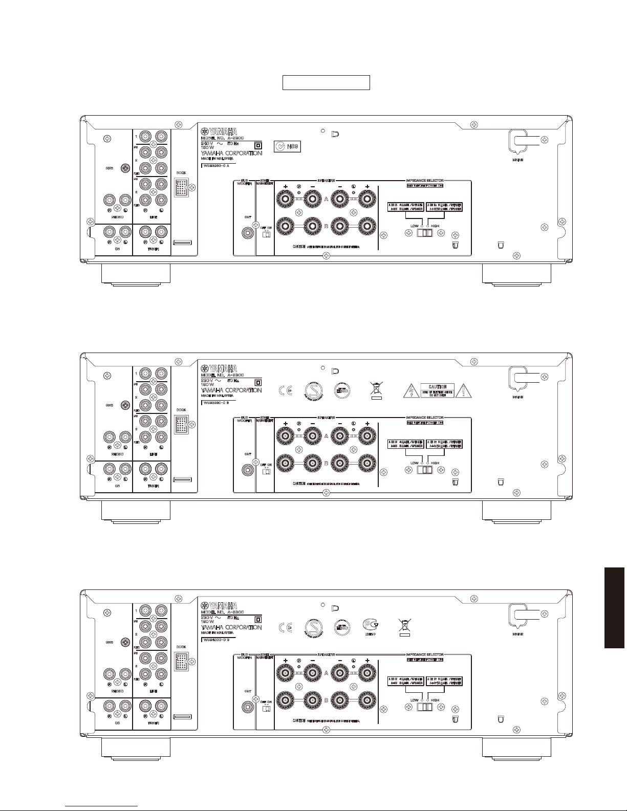
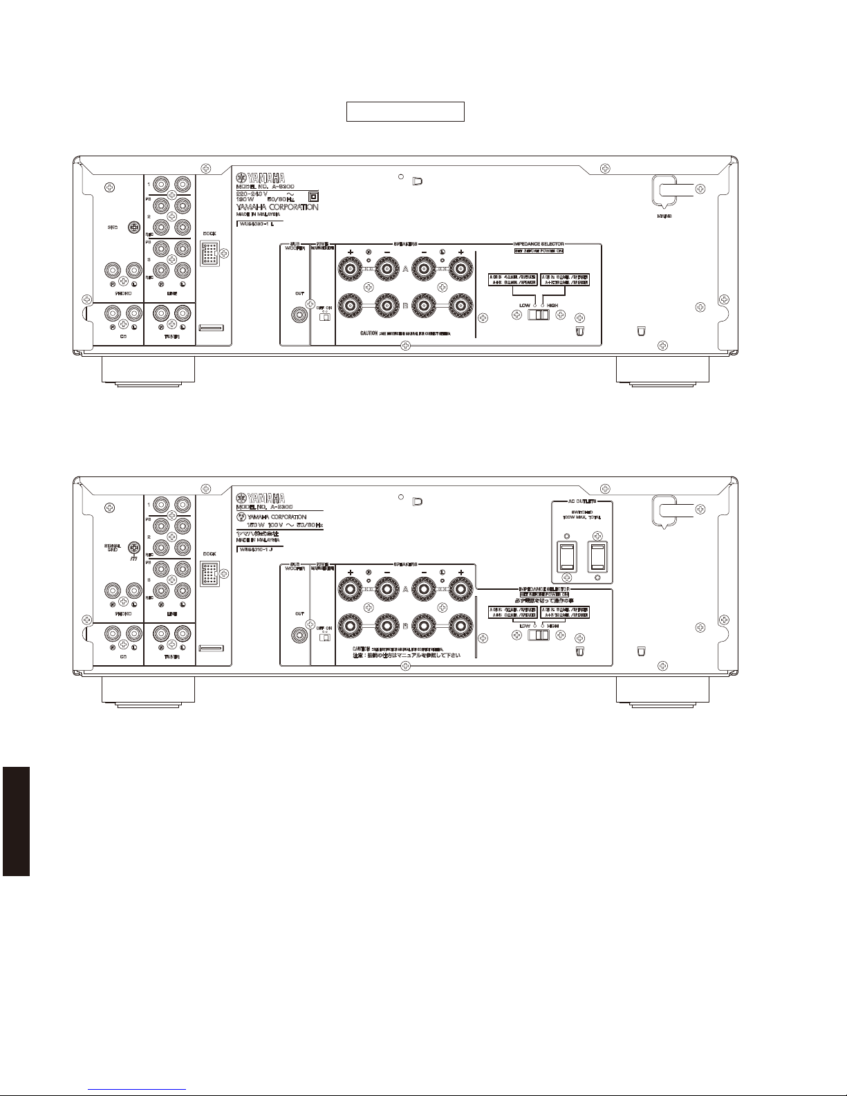
Power Supply / 電源電圧
U, C models ............................................................ AC 120 V, 60 Hz
R model ........................................AC 110-120/220-240 V, 50/60 Hz
T model ................................................................... AC 220 V, 50 Hz
A model .................................................................. AC 240 V, 50 Hz
B, G models ............................................................ AC 230 V, 50 Hz
L model ....................................................... AC 220-240 V, 50/60 Hz
J model .............................................................. AC 100 V, 50/60 Hz
Power Consumption / 消費電力
[A-S500]
U, C models ............................................................ 240 W, 330 VA
R, T, A, B, G models ............................................................. 240 W
L model ................................................................................ 220 W
[A-S300]
R, T, A, B, G, L models ......................................................... 190 W
J model ................................................................................ 150 W
Standby Power Consumption / 待機時消費電力
................................................................................ 0.5 W or less
YID-W10 Standby Power Consumption (YID-W10 connect) /
YID-W10 待機時消費電力(YID-W10 接続時)
................................................................................ 1.2 W or less
iPod Charge Power Consumption / iPod 充電時消費電力
[A-S500] .................................................................. 35 W or less
[A-S300] .................................................................. 25 W or less
Maximum Power Consumption [R model]
(1 kHz, 6 ohms, 10 % THD)
[A-S500] ..........................................................................510 W
[A-S300] ..........................................................................400 W
AC Outlets / AC アウトレット [J model]
[A-S300]
Switched x 2 .........................................................100 W max. total
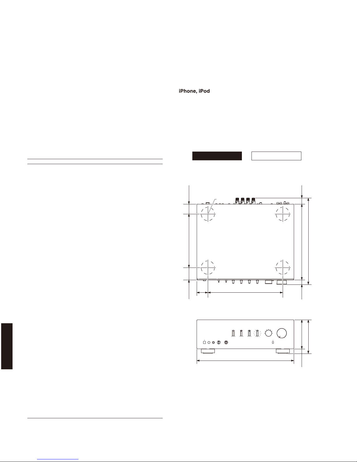
Dimensions (W x H x D) / 寸法(幅 × 高さ × 奥行き)
..............................435 x 151 x 387 mm (17-1/8" x 6" x 15-1/4")
Weight / 質量
[A-S500] .........................................................10.3 kg (22.7 lbs.)
[A-S300] ...........................................................9.0 kg (19.8 lbs.)
Finish / 仕上げ
Black color ................................. U, C, R, A, B, G, L, J models
Silver color ....................................... R, T, A, B, G, L, J models
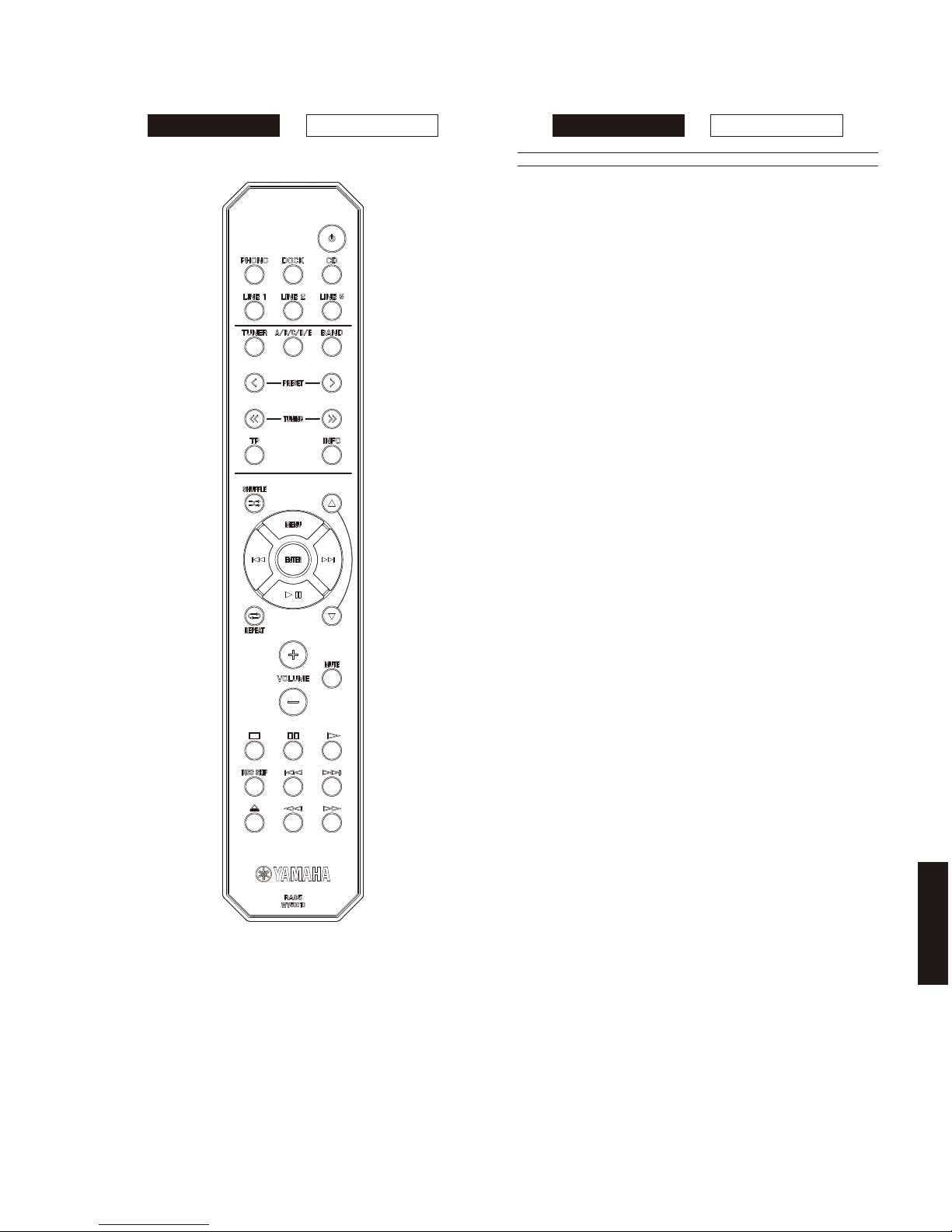
Accessories / 付属品
Remote control .......................................................................x 1
Battery (R6, AA, UM-3) ..........................................................x 2
*Specifications are subject to change without notice.
※ 参考仕様および外観は、製品の改良のため予告なく変更すること
があります。
U........................U.S.A. model
C..................Canadian model
R.....................General model
T..................... Chinese model
A .................Australian model
B.......................British model
G..................European model
L..................Singapore model
J .................. Japanese model
iPhone, iPod, iPod classic, iPod nano and iPod touch are trademarks of
Apple Inc., registered in the U.S. and other countries.
iPhone、iPod、iPodclassic、iPodnano、iPodtouch は、米国およびその他の国々
で登録されている AppleInc. の商標です。
Front view
Top view
435 (17-1/8")
335 (13-1/4")50
(2")
151 (5-7/8")
130 (5-1/8")
21
(7/8")
20.5
(3/4")
25.5
(1")
387 (15-1/4")
341 (13-3/8")
55
(2-1/8")
46
(1-3/4")
240 (9-1/2")
ø 60
Unit: mm (inch)
単位:mm(インチ)
A-S500 A-S300