10
A-S501/A-S301
A-S501/A-S301
Standby Power Consumption / 待機時消費電力
...................................................................................................0.5W
Maximum Power Consumption [Rmodel]
(1 kHz, 6ohms, 10 % THD)
[A‑S501].................................................................................510W
[A‑S301].................................................................................430W
Dimensions (W x H x D) / 寸法(幅× 高さ× 奥行き)
....................................... 435 x 151 x 387 mm (17‑1/8" x 6" x 15‑1/4")
Weight / 質量
[A‑S501].................................................................10.3kg (22.7 lbs.)
[A‑S301]...................................................................9.0 kg (19.8lbs.)
Finish / 仕上げ
Blackcolor ..................................................U,R,A,B,G,Lmodels
Silvercolor .......................................... U,T,K,A,B,G,L,Jmodels
Accessories / 付属品
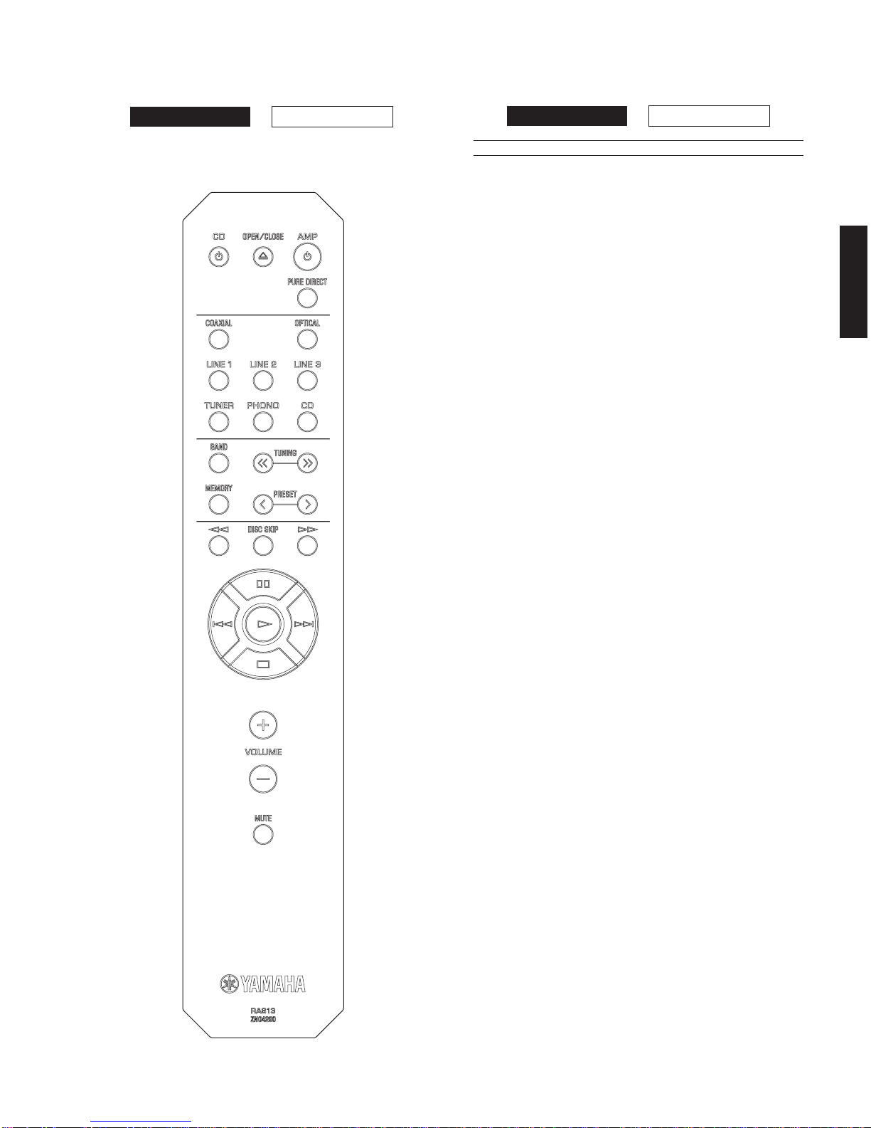
Remote control............................................................................... x 1
Battery(R6,AA,UM‑3).................................................................. x 2
* Specifications are subject to change without notice.
※参考仕様および外観は、製品の改良のため予告なく変更すること
があります。
U............................ U.S.A. and
Canadian models
R.................... General model
T.....................Chinese model
K ......................Korean model
A .................Australian model
B.......................British model
G................. European model
L................. Singapore model
J...................Japanese model
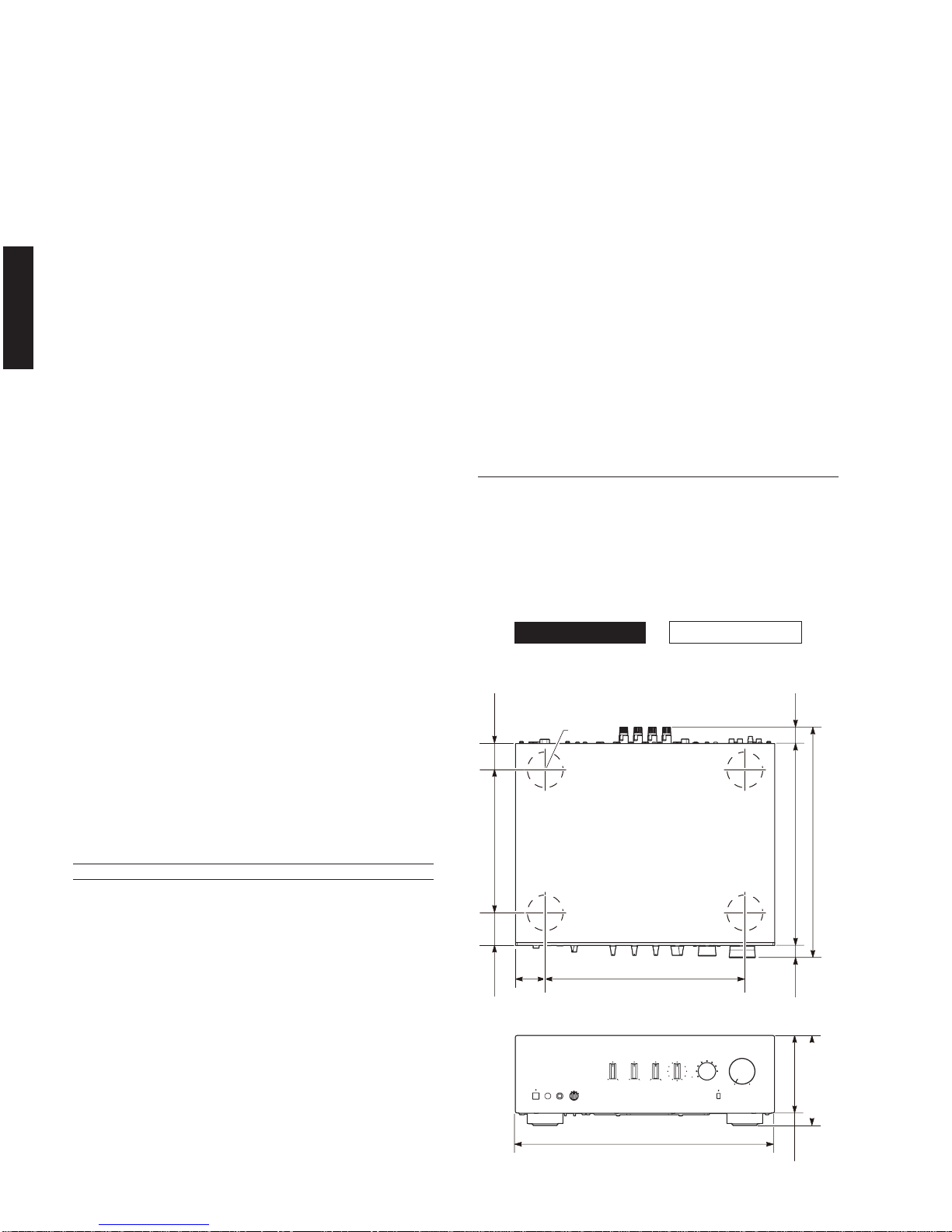
•DIMENSIONS / 寸法図
Frequency Response / 再生周波数帯域
CD, etc. (20 Hz to 20 kHz) ............................................... 0 ±0.5dB
CD, etc. Pure DIRECT ON (10 Hz to 100 kHz) ................0 ±1.0 dB
RIAA Equalization Deviation / RIAA 偏差
PHONO (MM) .......................................................................... 0.5dB
Total Harmonic Distortion / 全高調波歪率 (20Hzto20kHz)
PHONO (MM) to REC OUT (2.5V) ............................. 0.03% or less
[A‑S501]
CD,etc.toSPOUT(45W,8ohms)........................ 0.019 % or less
[A‑S301]
CD,etc.toSPOUT(30W,8ohms)........................ 0.019 % or less
Signal to Noise Ratio / 信号対雑音比 (IHF‑ANetwork)
PHONO (MM) (5mV Input shorted) ........................... 82 dBor more
CD, etc. (Pure DIRECT ON) (200 mV input shorted)... 99dBormore
Residual Noise / 残留ノイズ(IHF‑ANetwork)
................................................................................................ 40 μV
Channel Separation / チャンネルセパレーション
CD, etc. (Input 5.1 k‑ohms shorted)
1kHz......................................................................... 65dBormore
10 kHz....................................................................... 50dBormore
Tone Control Characteristics / トーンコントロール特性
BASS
Boost/Cut(20Hz)................................................................ ±10dB
Turnover frequency ...............................................................400Hz
TREBLE
Boost/Cut(20kHz)............................................................... ±10dB
Turnover frequency ..............................................................3.5kHz
Continuous Loudness Control /
コンティニュアスラウドネスコントロール
Attenuation /最大補正率 (1 kHz) ............................................. ‑30 dB
Supported Digital Audio Format (COAXIAL / OPTICAL) /
対応デジタルオーディオフォーマット (COAXIAL / OPTICAL)
.................................................192 /176.4 /96/88.2 /48/44.1 kHz
PCM Word Depth / 対応ビット長
............................................................................................ 16/24 bit
Gain Tracking Error / GAIN トラッキングエラー
(0 to ‑99 dB)..................................................................0.5dBor less
■General / 総合
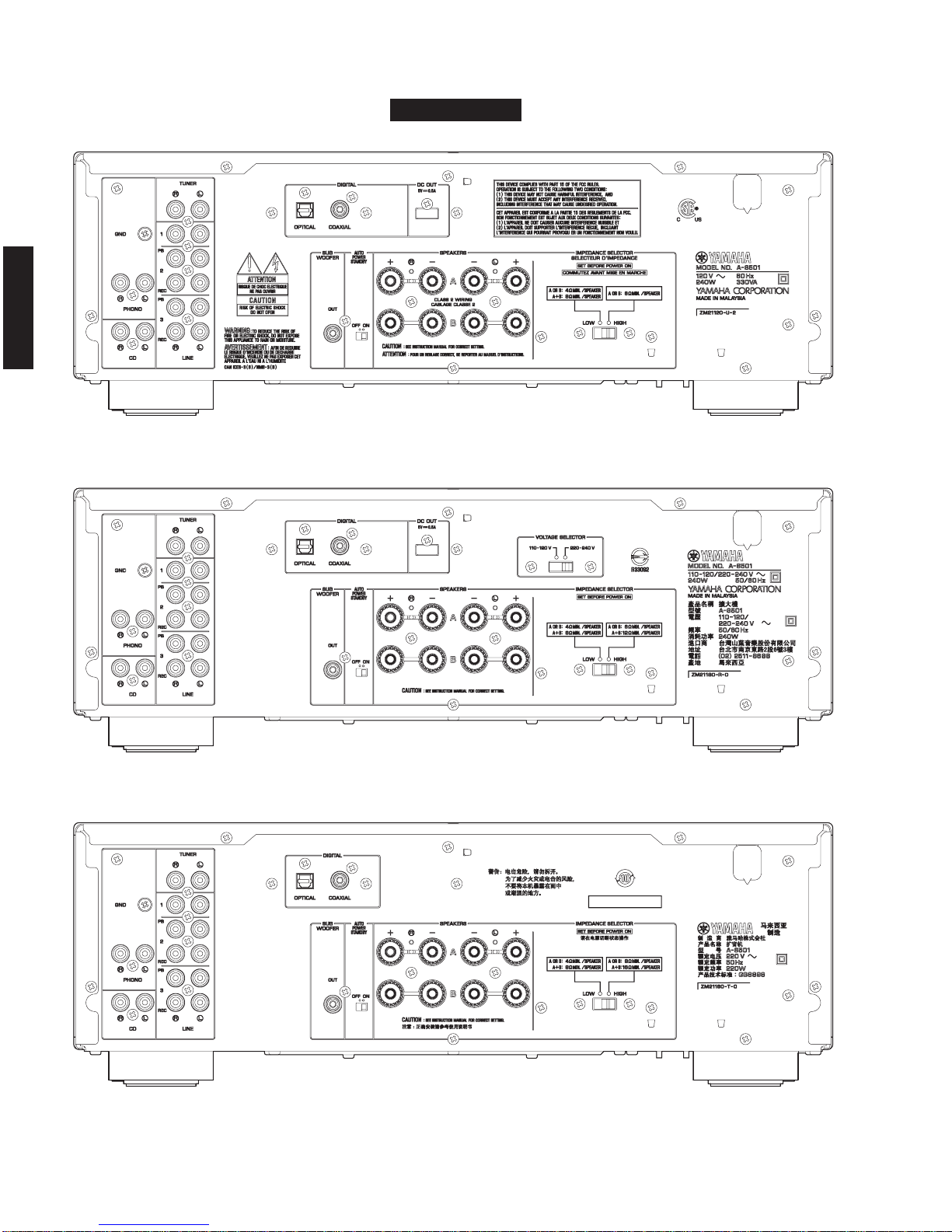
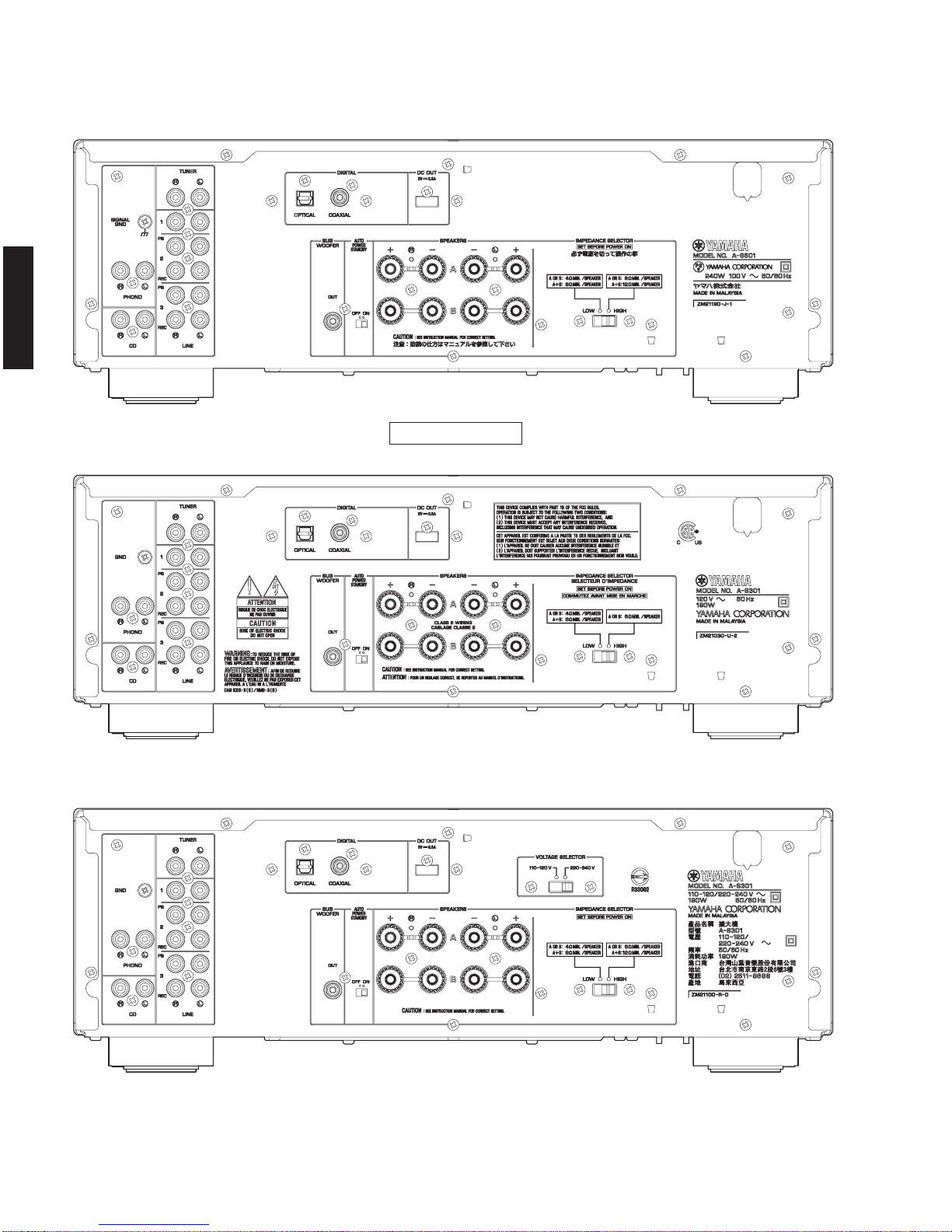
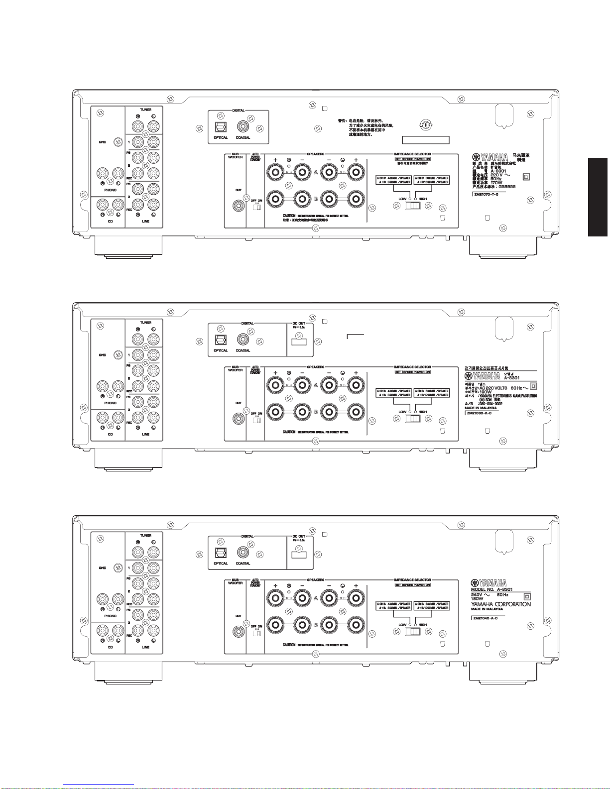
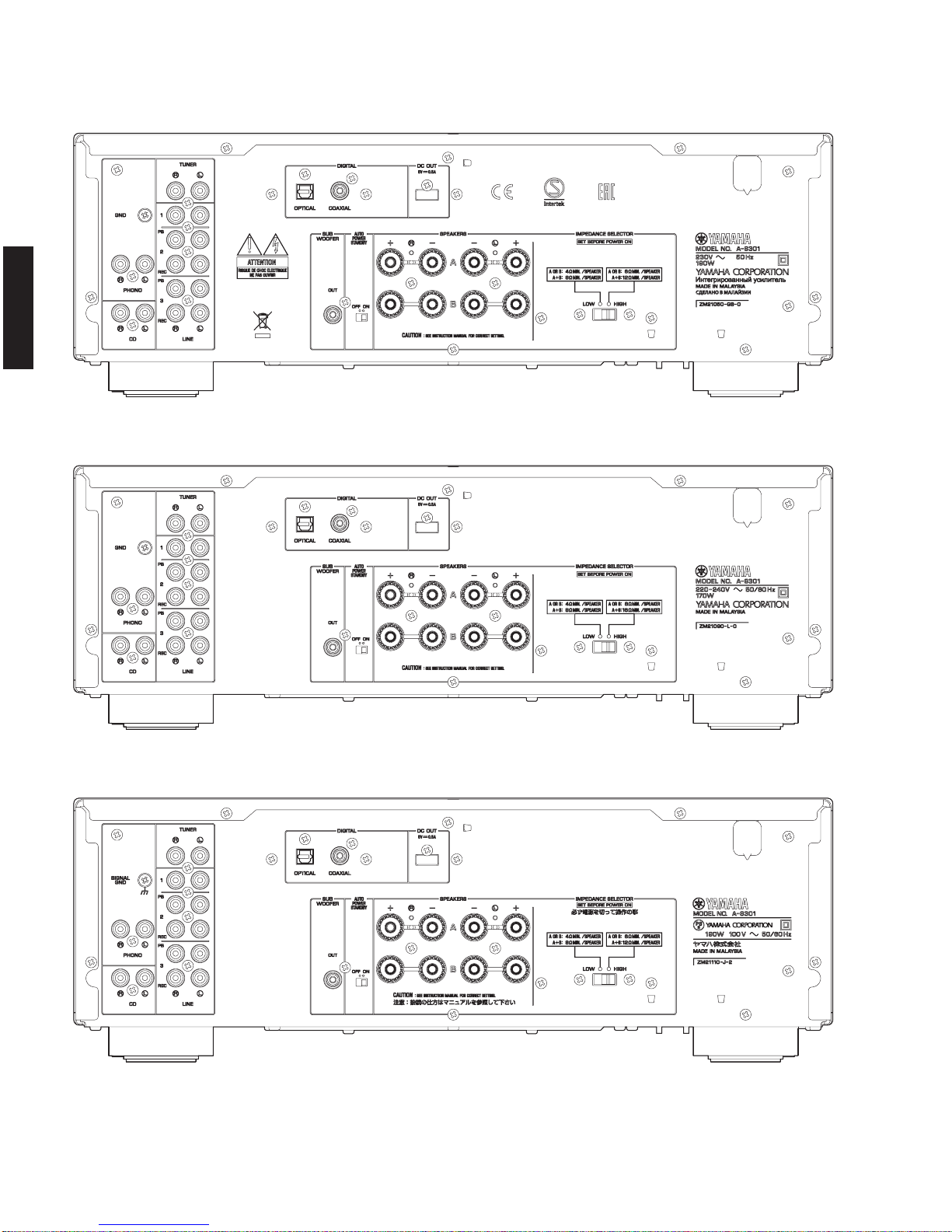
Power Supply / 電源電圧
U model ....................................................................AC 120 V, 60 Hz
R model ........................................ AC 110–120/220–240 V, 50/60 Hz
T model..................................................................... AC 220 V, 50 Hz
Kmodel ....................................................................AC 220 V, 60 Hz
Amodel ....................................................................AC 240 V, 50 Hz
B, Gmodels.............................................................. AC 230 V, 50 Hz
L model........................................................ AC 220–240 V
, 50/60 Hz
Jmodel ................................................................AC 100 V, 50/60 Hz
Power Consumption / 消費電力
[A‑S501]
U,R,A,B,G,Jmodels..........................................................240 W
T, L models.............................................................................220 W
[A‑S301]
U,R,K,A,B,G,Jmodels......................................................190 W
T, L models.............................................................................170 W
A-S301A-S501
Top view
Unit: mm (inch)
単位:mm(インチ)
335 (13-1/4")50
(2")
20.5
(3/4")
25.5
(1")
387 (15-1/4")
341 (13-3/8")
55
(2-1/8")
46
(1-3/4")
240 (9-1/2")
ø 60
Front view
435 (17-1/8")
151 (5-7/8")
130 (5-1/8")
21
(7/8")