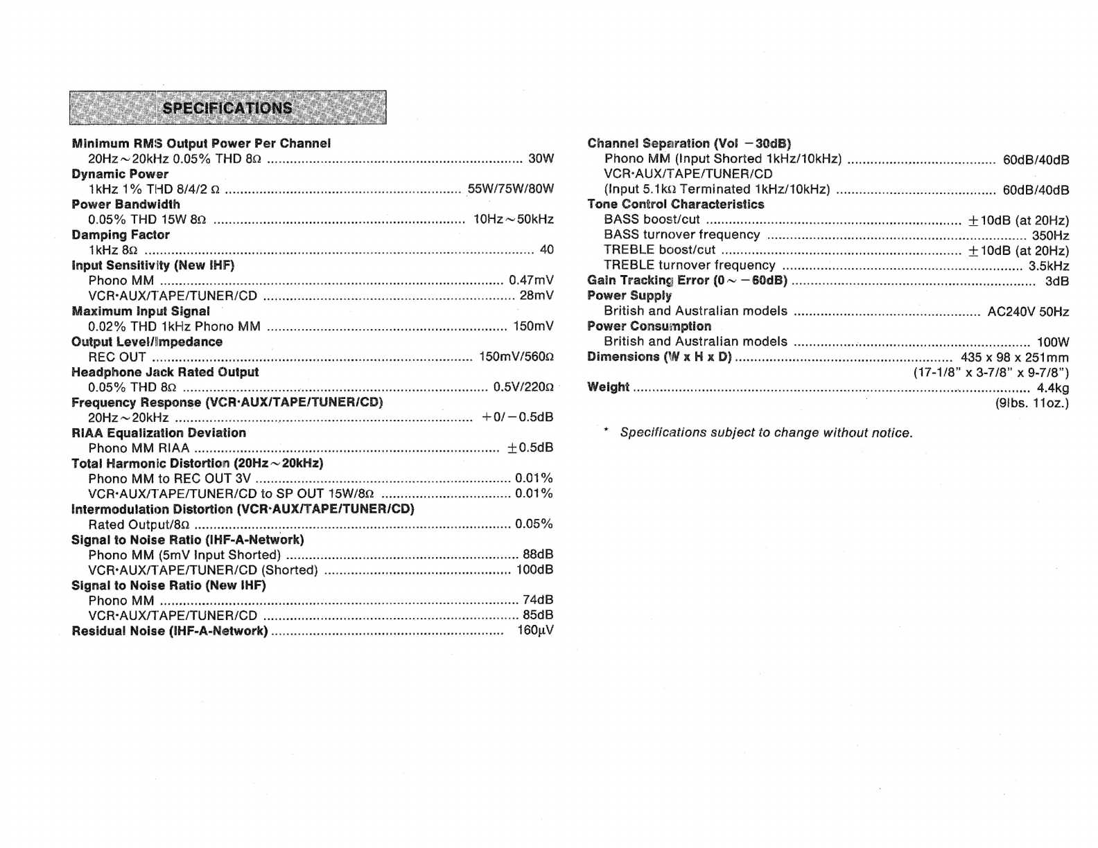
Yamaha AX-330e User manual

CONTENTS
ο
ος
ΓΤ
ΡΒΕΟΑΌΤΙΟΝΒ...............................
CONNECTION
DIAGRAM
.J...........
ΟΟΝΝΕΟΤΙΟΝΘ....|..........................
CONTROLS
AND
THEIR
FUNCTIONS
OPERATIONS
..................................
TROUBLESHOOTING
...
ΘΡΕΟΙΕΙΩΑΤΙΟΝΘ....,.........................
Pee
RNS
αλλ
Tea
VAS
xe:
dt
eu
par
ut
OWNER'S
MANUAL

Thank
you
for
purchasing
the
YAMAHA
Integrated
Amplifier.
In
order
to
ensure
proper
operation
for
the
best
possible
performance,
please
read
this
manual
thoroughly
before
connecting
up
your
new
amplifier
and
turning
it
on.
IMPORTANT!
Please
record
the
serial
number
of
your
unit
in
the
space
below.
Serial
No:
OWNER'S
MANUAL
Keep
this
manual
in
a
safe
place
for
future
reference.
LOCATION
Avoid
placing
your
unit
in
direct
sunlight
or
close
to
a
source
of
heat.
Also
avoid
locations
in
which
the
device
is
likely
to
be
subjected
to
excessive
dust,
cold
or
moisture.
VENTILATION
The
openings
on
the
cabinet
ensure
the
ventilation
of
the
amplifier.
lf
these
openings
are
obstructed,
the
temperature
inside
the
cabinet
will
rise
rapidly
and
eventually
damage
the
circuits.
Therefore,
avoid
placing
objects
against
these
openings
and
do
not
install
your
amplifier
in
a
place
such
that
the
flow
of
air
through
the
ventilation
openings
could
be
im-
peded.
HANDLING
@
Power
cord
|
When
removing
the
power
plug
from
the
wall
outlet,
always
pull
directly
on
the
plug.
Never
yank
the
cord
-
as
this
may
result
in
damage
to
the
cord
and
possibly
a
short-circuit.
lf
you
do
not
intend
to
use
this
unit
for
an
extended
period
of
time,
it
is
advisable
to
unplug
the
power
cord.
@
Switches
and
knobs
Avoid
applying
excessive
force
to
the
switches
and
knobs.
e
Relocation
Before
moving
your
amplifier,
be
sure
to
unplug
the
power
cord
and
remove
all
other
connecting
cables.
IN
CASE
OF
TROUBLE
@
Troubleshooting
Chart
Consult
the
Troubleshooting
Chart
for
advice
on
the
common
operation
errors
before
concluding
that
your
amplifier
is
faulty.
@
Servicing
Do
not
open
the
cabinet
or
attempt
to
make
repairs
by
yourself,
as
this
may
aggravate
the
damage
and
expose
you
to
an
electrical
shock.
&
Object
and
liquid
entry
|
585
to
it
that
foreign
objects
or
spilled
liquids
do
not
enter.
inside
the
cabinet.
Should
this
case
arise,
|
consult.
your
YAMAHA:
dealer.
/J.—
CLEANING
Wipe
off
dust
with
a
dry
soft
cloth.
To
remove
dirt
or
fingermarks,
use
a
soft
damp
cloth
then
dry
im-
mediately
with
a
clean
cloth.
Do
not
use
alcohol,
thinners
or
other
chemical
solvents
since
they
may
damage
the
finish
or
remove
the
panel
lettering.
Do
not
use
any
aerosol
sprays
near
this
unit
as
these
products
can
easily
get
into
the
unit
and
damage
the
circuitry.
SPECIAL
INSTRUCTIONS
FOR
THE
BRITISH
MODI
THE
WIRES
IN
THE
MAINS
LEAD
ARE
COL-
OURED
IN
ACCORDANCE
WITH
THE
FOLLOW-
ING
CODE:
Blue:
NEUTRAL
Brown:
LIVE
As
the
colours
of
the
wires
in
the
mains
lead
of
this
apparatus
may
not
correspond
with
the
coloured
markings
identifying
the
terminals
in
your
plug,
proceed
as
follows:
The
wire
which
is
coloured
BLUE
must
be
con-
nected
to
the
terminal
which
is
marked
with
the
letter
N
or
coloured
BLACK.
The
wire
which
is
coloured
BROWN
must
be
connected
to
the
ter-
minal
which
is
marked
with
the
letter
L
or
col-
oured
RED.

[56
imas
amm
GNO
—
SPEAKERS
TADE3w«:
REC
OUT
YOFVAOX
POND
WIRECT
€
LINE
IN/REC
COND
WIRE-
OUTPUT
LINE
OUT/PLAY
|
EH
L
i
io

The
connection
diagram
is
provided
on
page
3.
@
Video
player
@
Speakers
©)
Tape
deck
©
Turntable
{1}
Compact
disc
player
Before
making
any
connections
turn
off
all
equip-
ment.
Be
sure
to
connect
the
left
(L)
and
right
(R)
channels
consistently
between
components.
@
CONNECTING
THE
SPEAKERS
To
listen
through
headphones,
use
SWITCHED
SPEAKERS
terrninals.
No
sound
will
be
emitted
from
the
speakers
if
headphones
are
connected
to
the
unit.
To
listen
directly
from
the
speakers,
use
DIRECT
SPEAKERS
terminals.
Sound
signals
will
then
be
output
as
pure,
more
direct
sounds,
without
passing
through
the
headphones
output
circuit.
Note
that
both
terminals
should
never
be
used
at
the
same
time,
because
to
do
so
might
result
in
a
mal-
function.
Connect
the
cords
for
the
left
speakers
to
the
L
ter-
minals
and
the
right
speaker
cords
to
the
R
termi-
nals,
ensuring
that
the
polarity
(+
and
—)
markings
are
observed.
If
the
polarity
is
reversed
at
either
speaker
the
sound
will
be
unnatural
and
lack
bass.
Speaker
cords
should
be
cut
as
short
as
possible.
Avoid
coiling
the
wire
on
the
floor
or
bundling
it
up
with
cords
from
other
system
components.
When
connecting
to
SWTCHED
SPEAKERS
termi-
nals
Strip
off
about
10
mm
(3/8
in)
of
the
insulation
(leaving
only
the
core
wire)
from
the
end
of
each
speaker
connection
wire
to
be
connected
to
this
unit.
Press
the
lever
below
one
of
the
SPEAKER
con-
nection
terminals
and
insert
this
exposed
core
wire
into
the
hole,
as
shown
in
the
illustration.
When
the
lever
is
then
released,
the
cord
is
locked
in
securely.
RED
for
(+)
sign.
BLACK
for
(
—)
sign.
When
connecting
to
DIRECT
SPEAKERS
terminalis
Simply
insert
the
Banana
Chip
connector
into
the
corresponding
terminal.
e
CONNECTING
A
TURNTABLE
Connect
the
output
cords
of
the
turntable
to
the
amplifier
Phono
jacks
and
connect
the
ground
wire
|
to
the
GND
terminal.
Normally
connecting
the
ground
wire
produces
minimum
hum
but
in
some
cases
better
results
are
obtained
with
the
ground
wire
disconnected.
The
turntable
component
and
iis
output
cords
should
be
positioned
well
away
from
sources
of
hum
such
as
power
cords
or
power
transformers
of
other
system
components.
©
CONNECTING
A
TUNER
Connect
the
cords
from
the
Tuner’s
output
jacks
ti
the
TUNER
jacks
of
the
amplifier.
As
the
amplifier
power
supply
may
generate
a
certain
amount
of
radio
frequency
noise,
position
the
tuner
so
that
il
AM
antenna
is
well
away
from
the
amplifier.
e
CONNECTING
TO
THE
CD
AND
VCR/AUX
JACK
Connect
your
CD
component
to
the
CD
terminals
ar
video
sound
output
leads
the
VCR/AUX
terminals.
Please
note
that
a
turntable
cannot
be
connected
:
these
jacks
as
they
do
not
provide
the
necessary
RIAA
equalization.
©
CONNECTING
THE
TAPE
DECK
Connect
the
tape
deck’s
Line
In
jacks
to
the
amplifier's
Rec
Out
jacks,
ensuring
that
left
and
rig:
are
not
reversed.
Then
connect
the
tape
deck's
Lir
Out
jacks
to
the
amplifier's
Tape
PB
jacks.

"μα
PHONES
:
DEFEAT
|
1
É
1
2
iue
-5
O
POWER
SWITCH
(POWER)
Press
once
to
turn
the
power
ON
and
once
again
to
turn
the
power
OFF.
Before
turning
the
power
ON
set
the
volume
to
its
lowest
position
(extreme
counterclockwise),
to
protect
the
speakers
from
any
sudden
high
level
sound.
|
Q
POWER
ON
INDICATOR
Illuminated
when
power
is
ON.
Q
HEADPHONES
JACK
(PHONES)
Stereo
headphones
with
a
standard
plug
can
be
connected
to
this
jack.
@
BASS
CONTROL
KNOB
(BASS)
This
knob
controls
bass
response.
Turn
it
clockwise
to
boost
or
counterclockwise
to
attenuate
bass
re-
sponse.
When
this
knob
is
in
the
center
defeat
po-
sition
a
flat
response
is
obtained.
BASS
TREBLE
ODE
j
AT
,
i
|
z
2
=
{
πανε
3 3
3
fc
νὴ
4
a a
:
©
TREBLE
CONTROL
KNOB
(TREBLE)
This
knob
controls
treble
response.Turn
it
clockwise
to
boost
or
counterclockwise
to
attenuate
treble
re-
sponse.
When
this
knob
is
in
the
center
defeat
po-
sition
a
flat
response
is
obtained.
@
BALANCE
CONTROL
KNOB
(BALANCE)
This
knob
is
used
to
adjust
the
relative
volume
of
the
left
and
right
channels,
enabling
you
to
compensate
for
unbalance
created
by
installation
locations
of
the
speakers.
@
MAIN
DIRECT
SWITCH
(MAIN
DIRECT)
Pressing
this
switch
routes
the
audio
input
signal
directly
to
this
unit
output
stage,
bypassing
the
tone
controls
and
balance
control
circuits
for
the
purest
possible
sound.
Remember
that
none
of
the
controls
just
mentioned
will
have
any
effect
when
MAIN
DI-
RECT
is
pressed.
|
€)
TAPE
MONITOR
SWITCH
(TAPE
MONITOR)
Press
this
button
to
monitor
the
sound
from
a
tape
deck
connected
to
the
Tape
PB
jacks
on
the
rear
panel.
INPUT
SELECTOR
selects
the
program
source
you
wisn
to
listen
to.
W
VOLUME
CONTROL
KNOB
(VOLUME)
This
controls
the
sound
level.
Turning
clockwise
increases
the
sound
volume
and
turning
counter-
clockwise
decreases
it.
Set
this
knob
tothe
minimu
level
before
turning
the
power
ON
or
using
the
Inp
Selector
to
select
a
different
sound
source,
there-
fore,
protecting
the
speakers
from
any
sudden
hic
level
sound.

®
Normal
listening
operation
h
—
Turn
the
volume
control
to
the
minimum
level
before
turning
the
power
ON.
The
power
indicator
is
illuminated.
.
Select
the
desired
program
source
using
the
IN-
PUT
SELECTOR.
Activate
your
chosen
component.
Adjust
your
VOLUME,
BASS,
TREBLE
and
BAL-
ANCE
to
provide
the
desired
sound
quality.
To
record
from
a
program
source
.
Turn
the
volume
control
to
the
minimum
setting
then
press
the
power
switch
(to
the
ON
position).
The
power
indicator
lights
up.
.
Select
the
desired
program
source
using
the
IN-
PUT
SELECTOR.
Ensure
the
Tape
Monitor
is
OFF.
.
Activate
the
source
program
component.
.
Advance
the
volume
control
to
a
suitable
level.
.
Commence
recording
by
activating
the
tape
deck
-
connected
to
the
Tape
jacks.
.
The
recording
can
be
monitored
through
the
speakers
or
headphones.
If
the
tape
deck
has
3
head
monitoring
capability
the
just
recorded
signal
can
be
monitored
by
depressing
the
Tape
Monitor
switch.
Before
assuming
that
your
unit
is
faulty,
please
check
the
following
troubleshooting
list
which
details
the
correcti\
action
you
can
take
yourself
without
having
to
call
a
service
engineer.
If
you
have
any
doubts
or
questions,
contac
your
nearest
Yamaha
dealer.
Power
is
not
supplied
even
though
the
Power
switch
is
turned
on.
The
power
plug
is
not
securely
plugged
Plug
it
in
securely.
In.
There
is
nosound
with
any
input
selector
switches
pressed.
The
Speakers
switch
is
not set
correctly.
|
Set
the
Speakers
switch
correctly.
The
input
cords
are
not
connected
se-
Connect
them
securely.
curely.
.
The
speaker
system
is
not
connected
Check
and
secure
connections.
correcily.
The
Tape
Monitor
is
ON.
Push
the
Tape
Monitor
switch
to
th
OFF
position.
There
is
no
sound
from
one
Secure
the
connections.
speaker.
The
speaker
connections
are
not
secure.
The
Balance
control
is
set
all
the
way
to
the
left
or
right.
Adjust
the
Balance
control
cor-
rectly.
There
is
a
lack
of
bass
and
no
ambience.
The
+
and
—
cords
have
been
reversed
at
the
amp
or
speakers.
Connect
the
speaker
wires
in
the
correct
phase
(+
and
—}.
There
is
a
humming
sound
when
playing
records.
The
input
cords
are
not
connected
se-
curely.
Plug
the
input
cords
in
securely.
The
turntable’s
ground
wire
is
not
con-
nected.
Connect
the
ground
wire.
There
is
a
howling
sound
when
playing
records
at
high
volume.
The
turntable
and
the
speakers
are
too
close
together
or
the
turntable
is
not
mounted
on
a
firm
surface.
Change
the
location
of
the
turntabl
or
the
speakers.
Driving
speakers
outside
the
rated
impe-
dance
range
at
high
power
for
an
extended
period
has
activated
the
speaker
pro-
tection
circuit.
Turning
this
unit
off
and
then
on
wi
reset
the
speaker
protection
circui
Use
speakers
inside
the
rated
im-
pedance
range.
The
sound
suddenly
goes
off.
There
is
a
malfunction
in
the
amplifier.
Consult
your
Yamaha
dealer.

Minimum
RMS
Output
Power
Per
Channel
20Hz
20K
2
005%
THD
60.
4.
utt
ο
το
ο
ο
ο
ο
utu
ο.
30W
Dynamic
Power
Ikiz
195:
ΠΡ
8/4/28
ο
ο
ο
αν
Ci
voe
ao
ανν
55W/75W/80W
Power
Bandwidth
|
00S
ΤΗΡΊ5
BO
eec
occ
FR
atuba
Ruido
nt
Dalee
aides
eoi
santas
anes
10Hz
~
50kHz
Damping
Factor
EIZ
OO
Np
40
input
Sensitivity
(New
IHF)
Phono
MM
PP
——-——————P—
0.47mV
VORSAUX/TAPEFTUNER/GD.-
ο
ας
x
E
aa
Ra
es
pF
endows
28mV
Maximum
Input
Signal
|
0:02
95
TED
TKEIZ
Phono
MM...
de
ον
eco
tea
t
T
150mV
Output
Level/Impedance
|
REO
OUT
ossia
da
reste
ο
nee
e
ο
ο
ο
150mV/5600
Headphone
Jack
Rated
Output
|
0:057
THD
8D.
iusto
peo
oper
epe
cs
——
MÀ
—
ο.
0.5V/2200
»
Frequency
Response
(VCR-AUX/TAPE/TUNER/CD)
|
20HZ
~
20KHIZ
iiid
dr
iei
ο
M
et
ον
ο
E
Eon
UE
--
0/
—
0.5dB
RIAA
Equalization
Deviation
Phono
MM
RIAA
«cre
claw
a
ο
ο
ο
cese
ον
+0.5dB
Total
Harmonic
Distortion
(20Hz
~
20kHz)
|
Phono
MM
to
REC
OUT
SV...
incerti
ασε asa
tuse
abe
tons
η
σκι
EE
Ra
δε
ριθέ
νέος
0.01%
VCR-AUX/TAPE/TUNER/CD
to
SP
OUT
15W/80
................
eese
0.01%
intermodulation
Distortion
(VCR-AUX/TAPE/TUNER/CD)
Rated
OUIpitU
BO
ciii
ο
ος
ος
ος
ο
ο.
0.05%
Signal
to
Noise
Ratio
(IHF-A-Network)
Phono
MM
(5mV
Input
Shorted)
.0........
eee
νενο
νε
κκεννωκκεω
νερο
κε
εοκ
κ
εκ
κε
νακεκσ
ας
88dB
VCR:AUX/TAPE/TUNER/CD
(Shorted)
..............ινιννονννννονννννένννννρέννεννννεν
100dB
Signal
to
Noise
Ratio
(New
IHF)
PRONO
MM
Sod
des
ο
M
Over
md
ta
ο
ο
ο
ο
ο
ουν
74dB
VOIR
AUXFTAPEFTUNER/GD'
ridite
iaa
b
xv
Eit
opua
Vere
gerne
AAT
85dB
Residual
Noise
(IHF-A-Network)
...................sessseeeenem
m
HH
160uV
Channel
Separation
(Vol
—30dB)
Phono
MM
(Input
Shorted
1kHz/10kHz)
................
Mb
e
HE:
60dB/40dB
VCR:AUX/TAPE/TUNER/CD
|
(Input
5.1kQ
Terminated
1kHz/10KkHz)
...........................οινοοενννιννν.
60dB/40dB
Tone
Control
Characteristics
BASS:
ρε
να
ο
το
ο
Ede
ease
--
+
10dB
(at
20Hz)
BASS
turnover
ώς
ο
ο
ο
edv
ondes
ο
Le
Iu
DE
Det
auc
es
350Hz
THEBLUEDOOSUGHE
οἱ.:οκοζκοικεζοαώαἲόνίαςκεώοσσδεώνεὟ
εισοδο
μόνα,
+
10dB
(at
20Hz)
TREBLE
turnover
frequency
νώτα
e
eae
Lo
ee
rre
n
ort
bes
v
PRSE
σος
3.5kHz
Gain
Tracking
Error
(0~
-604Β).................................-.οοιονοονοονοννννννννοννονον.
3dB
Power
Supply
|
British
and
Australian
models
.................................
προ
AC240V
50Hz
Power
Consumption
|
British
and
Australian
models
.................
pelas
ο
ipae
E
dune
dua
qe
E
100W
Ὠίϊπιβπβϊιοπ6ο(νκηκΏ)..............................ιννννννννννννννννννννννννν,
435
x
98
x
251mm
(17-1/8"
x
3-7/8"
x
9-7/8")
ο
νο
e
—
οονοί
4.4kg
(9ibs.
1197.)
.*
Specifications
subject
to
change
without
notice.

YAMAHA
ELECTRONICS
CORPORATION,
USA
6660
ORANGETHORPE
AVE.,
BUENA
PARK,
CALIF.
90620,
U.S.A.
YAMAHA
CANADA
MUSIC
LTD.
135
MILNER
AVE.,
SCARBOROUGH,
ONTARIO
M1S
3R1,
CANADA
YAMAHA
ELECTRONIK
EUROPA
G.m.b.H.
2084
RELLINGEN,
BEI
HAMBURG,
SIEMENSSTR.
22/34,
Ε.Β,
OF
GERMANY
YAMAHA
ELECTRONIQUE
FRANCE
S.A.
17
RUE DES
CAMPANULES,
LOGNES
77321
MARNE
LA
VALLEE
CEDEX
2,
FRANCE
YAMAHA
ELECTRONICS
(UK)
LTD.
YAMAHA
HOUSE,
200
RICKMANSWORTH
ROAD
WATFORD,
HERTS
WD1
705,
ENGLAND
l
YAMAHA
CORPORATION
YAMAHA
SCANDINAVIA
A.B.
J
A
WETTERGRENS
GATA
1,
BOX
30053,
400
43
VÄSTRA
FRÖLUNDA,
SWEDEN
10-4
NAKAZAWA-CHO,
HAMAMATSU,
JAPA
YAMAHA
MUSIC
AUSTRALIA
PTY,
LTD.
17-33
MARKET
ST.,
SOUTH
MELBOURNE,
3205
VIC.,
AUSTRALIA
VH10360-0
Printed
in
Japan
BWgW,
G
Table of contents
Other Yamaha Amplifier manuals

Yamaha
Yamaha AV-75PRO User manual

Yamaha
Yamaha YST-A5 User manual

Yamaha
Yamaha DSP-A500 User manual

Yamaha
Yamaha M-40 User manual

Yamaha
Yamaha DSP-Z9 User manual

Yamaha
Yamaha C-4 User manual

Yamaha
Yamaha DSP -A780 User manual

Yamaha
Yamaha DSP-A990 User manual

Yamaha
Yamaha M-4 User manual

Yamaha
Yamaha MX-A5000 User manual

Yamaha
Yamaha AG-Stomp User manual

Yamaha
Yamaha MLA8 User manual

Yamaha
Yamaha RX-V3300 User manual

Yamaha
Yamaha AX-596 User manual

Yamaha
Yamaha AR-1500B User manual

Yamaha
Yamaha C-85 User manual

Yamaha
Yamaha Portatone PSR A1000 User manual

Yamaha
Yamaha T3n User manual

Yamaha
Yamaha CA-2010 User manual

Yamaha
Yamaha MX-600 /U User manual