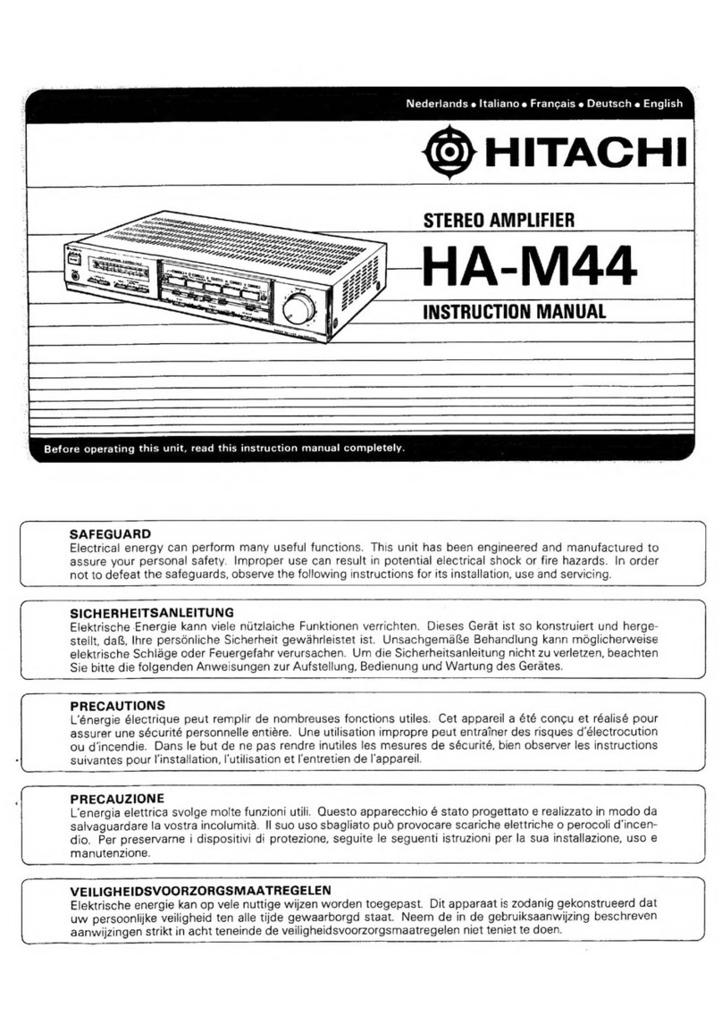
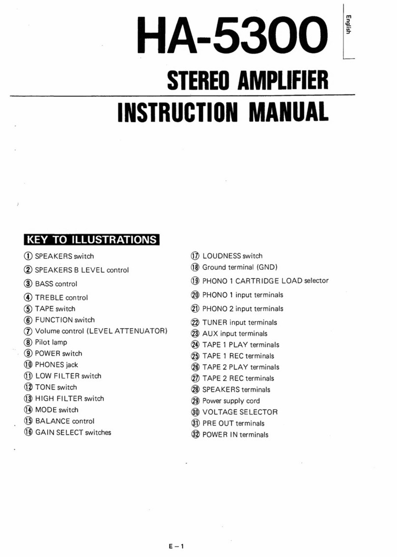
Hitachi IA-1200 User manual

HITACHI
HI-Fl
COMPONENT
I[A-1200
INTEGRATED
AMPLIFIER
INSTRUCTION
MANUAL
Hitachi,
Ltd.
Tokyo
Japan

Thank
you
very
much
for
purchasing
HITACHI
integrated
amplifier
IA-1200.
TA-1200
is
a
versatile,
high
performance
amplifier
designed
for
use
by
music
lovers.
It
has
four
built-in
main
amplifiers,
which
makes
it
possible
to
use
this
equipment
in
three
ways;
as
full
range,
multi-channel,
and
center
woofer
systems.
For
the
heart
of
this
equipment
HITACHI
silicon
transistors
of
high
reliability
are
used,
which
will
please
you
with
low
distortion
sound
over
a
wide
dynamic
range.
A
variety
of
built-in
accessory
Circuits
are
designed
to
suit
every
kind
of
program
source
in
the
best
condition.
Before
using
IA-1200,
please
read
this
instruction
manual
so
that
you
can
bring
the
performance
of
this
equipment
into
full
play.
CONTENTS
Handling
of
front
KnNObDS
.........cccccssscsssessccesecccecstearscssenses
3-4
Connection
of
rear
terminals
.........:sccsssscsssesesesessecsesceeeeses
5-6
Connection
of
speakers
.......:ssscsscccssscessscsecersessessaseesesenss
7-9
Cautions
during
use
...........sc0e
si
apiQuacthnts
DeaeudSesvaadeoucaadveens
10
Example
of
construction
of
stereo
system
...s.:ssseseree
11-12
Specifications
............
aban
Sesauadadadesweasucedscuesuuacealsscdscosocceue
13-14
CARACTONISHIG:
-
si
ccdadesececui
wis
ccatacausadasauilecSasuvedensdcitecneintack
15-16
Cireuit
Gidgranni:
teescidecdonsasatcasemnccctuvecde
evideesce
GEE
eaesbdacacocces
18

HITACHI,
Ltd.
has
been
devoting
its
effort
to
the
development
of
a
series
of
audio
equipment
and
high
class
Hi-Fi
components
of
high
performance
and low
distortion.
HITACHI
has
put
this
1A-1200
on
the
market
with
confidence.
@
Before
using
.........
Be
sure
to
turn
off
the
power
switch
when
you
remove
the
cover
in
order
to
insert
the
filter
unit
or
to
operate
the
channel
select.
Be
sure
that
the
ventilation
holes
on
the
amplifier
cover
are
not
blocked,
and
do
not
place
this
equipment
in
direct
sunlight,
because
transistors
are
susceptible
to
heat
and
excessive
heat
causes
troubles.
Pay
attention
for
efficient
radiation
of
heat
during
use.

@
Handling
of
Front
Knobs
@
Mode
switch
(MODE)
A
five
-position
switch
for
different
uses.
REVERSE
sound
emitted
from
the
left
and
right
speakers
is
reversed.
STEREO
reproduction
in
normal
stereo.
LEFT
signals
from
the
left
input
terminal
are
teproduced
by
both
left
and
right
speakers.
RIGHT
signals
from
the
right
input
terminal
are
reproduced
by
both
left
and
right
speakers,
L+R
left
and
right
signals
are
reproduced
by
left
and
right
speakers
after
being
mixed.
Reproduction
of
a
monaural
record
at
this
position
is
accomplished
with
less
noise.
@
Power
switch
(POWER)
When
this
switch
is
pushed
toward
ON,
the
pilot
lamp
above
it
comes
on
and
power
is
supplied.
@
Microphone
jack
(MIC)
Sensitivity
of
1.5
mV
and
flat
charac-
~
teristic.
Usable
for
a
microphone
having
an
impedance
less
than
10
kQ.
Regardless
of
the
position
of
the
mode
switch,
the
mode
becomes
L
+
R
state
when
a
microphone
is
plugged
into
this
jack
so
that
signals
from
one
microphone
-are
reproduced
by
both
left
and
right
speakers.
This
jack
will
facilitate
com-
mentary
at
a
record
concert
and
public-
address
use.
@
Function
switch
(FUNCTION)
For
selection
of
program
sources
which
you
prefer.
@
Power
limit
(POWER
LIMIT)
Position
this
lever
according
to
the
allowable
speaker
input.
Usually,
the
allowable
instantaneous
speaker
input
is
more
than
three
times
the
allowable
continuous
input.
The
indication
is
the
total
value
of
all
channels.
@
Monitor
(MONITOR)
When
reproducing
sound
using
a
tape
deck,
push
this
lever
toward
TAPE
position.
While
recording
sound
on
a
three-head
tape
recorder,
you
can
sim-
ultaneously
monitor
the
recording
con-
dition
by
positioning
this
lever
at
TAPE.
@
Bass
contro!
(BASS)
Bass
adjustment
in
a
range
of
+12
dB
at
100
Hz
can
be
made
for
left
and
right
speakers
separately.

‘
i
@
Low
filter
(LOW
FILTER)
When
this
switch
is
ON,
rumble
of
a
turntable,
low
frequency
noise
in
a
record,
and
low
frequency
noise
due
to
a
microphone
are
attenuated
by
8
dB
at
30
Hz.
This
switch
functions
regard-
less
of
the
setting
of
the
defeat
switch.
@
Treble
control
(TREBLE)
Treble
adjustment
in
a
range
of
+12
dB
at
10
kHz
can
be
made
for
left
and
tight
speakers
separately.
@
Tone
defeat
(DEFEAT)
When
this
lever
is
pushed
down
adjust-
ment
of
treble
and
bass
becomes
possi-
ble,
and
when
pushed
up
a
flat
char-
acteristic
is
obtained
regardless
of
the
position
of
the
control
knobs.
e@
Speaker
select
(SPEAKER
SELECT)
This
is
an
ON-OFF
switch
for
two
sets
of
the
four
built-in
main
ampli-
fiers.
For
operation
of
this
switch,
refer
to
the
section
on
connection
of
speakers.
@
Balance
(BALANCE)
This
is
for
adjusting
the
left
and
right
output
levels.
Adjust
so
that
the
volume
of
sound
from
the
left
and
right
speakers
balances
at
the
listening
posi-
tions.
e@
Volume
(VOLUME)
This
is
for
adjusting
the
volume
of
sound.
e
High
filter
(HIGH
FILTER)
When
this
switch
is
ON,
scratches
from
a
used
record
and
high
frequency
noise
of
AM
broadcasting
can
be
at-
tenuated
by
8
dB
at
10
kHz.
This
switch
functions
regardless
of
the
set-
ting
of
the
defeat
switch.
:
@
Speaker
switch
(SPEAKER)
While
in
use
this
switch
is
positioned
at
ON.
When
positioned
at
MUTE
the
output
is
decreased
to
1/10
(10
dB).
It
is
possible
to
decrease
sound
without
decreasing
the
volume
when
a
record
is
exchanged
or
when
it
is
desired
that
the
volume
of
sound
be
decreased
temporarily.
When
positioned
at
OFF
no
sound
is
reproduced
from
the
speakers.
When
a
headphone
is
used,
position
this
switch
at
OFF.
e@
Headphone
jack
(PHONES)
To
this
jack
a
headphone
with
an
impedance
of
8©
can
be
connected.
Because
of
a
built-in
amplifier
for
exclusive
use
with
the
headphone
this
jack
can
be
used
regardless
of
the
main
amplifier.

@
Connection
of
Rear
Terminals
ee
ee
Connecting
jack
for
pre-
amplifier
and
main
amplifier
By
the
use
of
this
jack
the
pre-
amplifier
and
main
amplifier
can
be
used
separately.
This
jack
will
facilitate
increasing
the
number
of
channels
of
a
multi-channel
amplifier.
Changeover
is
accom-
plished
by
CONNECTOR
switch.
@
Speaker
terminal
(SPEAKERS)
Different
connecting
methods
are
employed
depending
on
uses.
Re-
fer
to
the
section
on
connection
of
speakers.
@
Power
source
socket
(AC
OUT-
LET)
This
supplies
power
to
a
tape
recorder,
record
player,
tuner,
etc.
The
socket
marked
SWITCHED
socket
is
independent
of
the
power
switch.
@
Fuse
holder
2A
fuse
is
contained.
®
Power
cord
fe
ee
@
Input
and
output
jacks
for
tape
deck
Connect
a
tape
deck
having
a
head
output
jack
to
TAPE
HD
jack
(equalizer
is
NAB
of
19
cm/s).
Connect
a
tape
deck
having
a
built-in
preamplifier
to
TAPEMON-
ITOR
jack
for
playback
and
to
REC.OUT
jack
for
recording.
Con-
@
Main
A
channel
level
(MAIN
A
CH
LEVEL)
When
using
this
equipment
as
a
multi-channel
or
center
woofer
amplifier,
adjust
this
knob
so
that
the
volume
of
treble
is
balanced
with
bass.
Left
and
right
channels
can
be
adjusted
independently.

nect
a
tape
deck
having
a
DIN
jack
to
REC/PB
socket,
and
re-
cording
and
playback
can
be
ac-
complished
with
a
single
cord.
In
this
case
do
not
use
MON-
ITOR
jack
or
REC.OUT
jack.
LEVEL
ADMUST
TUNER
Fare
np
oxte)
AUK,
o
Ground
Terminal
(EARTH)
@
Level
adjust
(LEVEL
ADJUST)
This
matches
the
volume
of
AUX
and
TUNER
with
that
of
record
playback.
While
recorded
sound
is
being
reproduced
turn
the
func-
tion
switch
to
AUX
and
TUNER
positions
without
turning
the
volume
knob
and
adjust
the
volume
of
sound.
me.
@
Tuner
and
auxiliary
input
terminals
Input
sensitivity
is
higher
than
50
mV
for
both
tuner
and
auxil-
iary
input.
Input
impedance
is
higher
than
100
kQ.
Frequency
characteristic
is
flat.
Adjust
the
input
level
by
the
level
adjust
knobs
on
this
rear
panel.
Gc
@
PHONO
1.
Input
sensitivity
is
1.5
mV.
Con-
nect
a
record
player
having
a
cartridge
with
an
output
of
1
-
3
mV
(cut
level
of
5
cm/s.)
@
PHONO
2.
Input
sensitivity
is
5
mV.
Con-
nect
a
record
player
having
a
cartridge
with
an
output
of
3
-
10
mV
(cut
level
of
5
cm/s.)
Inptt
impedance
is
50
kOfor
both
PHONO
|
and
2,
and
the
equalizer
is
of
RIAA
standard.
|
@
Microphone
jacks
Sensitivity
is
1.5
mV.
and
the
characteristic
is
flat.
A
micro-
phone
with
less
than
10
kQ
impedance
can
be
used.
While
the
microphone
jack
on
the
front
panel
is
in
use
this
microphone
jack
cannot
be
used.

'
}
i
}
@
Connection
of
speakers
Several
ways
of
speaker
connection
are
possible
with
IA-1200
by
turning
the
channel
select
switch.
Be
sure
to
connect
speakers
to
the
correct
terminals.
(Channel
select
switch
will
be
found
in
the
amplifier
when
the
cover
is
removed.
Before
handling
this
switch
be
sure
to
turn
off the
power
switch.)
A
Socket
for
filter
unit
B
Channel
select
switch
@
Full
range
connection
Block
diagram
for
full
range
connection
Connecting
jack
for
4
preamplifier
and
Preamplifier
main
amplifier
cle
Connecting
jack
for
preamplifier
and
main
amplifier
Phase
inversion
circuit
@
When
one
pair
of
speakers
are
used
In
case
two
30
W
speakers
are
used.
(30W
x
2)
Connect
to
A
channel
or
B
channel
and
position
the
speaker
select
switch
at
A
or
B.
Even
if
the
unused
channel
is
left
open,
electric
shock
or
trouble
will
not
be
caused.
(Fig.
1)
(30W
X
2)
Fig.
1

In
case
two
60
W
speakers
are
used.
(60W
x
2)
Connect
to
the
respective
plus
terminals
of
A
channel
and
B
channel.
When
speakers
with
a
low
allowable
input
are
connected,
the
maximum
output
can
be
limited
by
the
power
limit
on
the
front
panel.
Position
the
speaker
select
switch
at
A
+
B.
(Fig.
2)
(60W
X
2)
Fig.
2
@
When
two
pairs
of
speakers
are
used.
In
case
four
30
W
speakers
are
used.
(30
W
x
4)
Channels
are
switched
by
the
speaker
select
switch
on
the
front
panel
to
A
channel
alone
or
B
channel
alone
or
A
+
B
channels.
Only
when
two
pairs
of
speakers
are
used
connect
the
speakers
of
B
channel
\
reverse
polarity.
(Since
the
phase
inversion
circuit
is
inserted
in
B
channel,
it is
necessary
to
reverse
the
polarity
of
B
channel
to
conform
the
phase
of
B
channel
to
that
of
A
channel
when
both
A
and
B
channels
are
used
in
the
same
room.)
(Fig.3)
{30W
x
4)
Fig.
3
@
In
case
of
2-way
multi-channel.
Set
the
channel
select
switch
in
the
equipment
at
the
position
of
multi-channel.
Then
insert
two
commercially
available
filter
units
(one
each
for
left
and
right
channels)
in
the
filter
unit
sockets.
(Be
sure
to
turn
off the
power
switch,
otherwise
the
units
might
be
damaged
by
shock
due
to
insertion.)
@
Block
diagram
for
multi-channel
=e
jack
for
preamplifier
Dividing
circuit
Main
amplifier
and
main
amplifier
BR
Preamplifier
|
BL
CS.
Dividing
Main
amplifier
Connecting
jack
circuit
for
preamplifier
and
main
amplifier
Connect
speakers
to
the
amplifier
in
such
a
way
that
the
plus
poles
of
speakers
are
connected
to
the
plus
terminals
of
the
amplifier,
and
minus
poles
to
minus
terminals.
A
channel
is
for
treble
range
and
B
channel
for
bass
range.
Adjust
the
level
of
the
tweeter
by
MAIN
A
CH
LEVEL
knob.
Turn
it
fully
counterclockwise
at
first,
then
turn
it
clockwise
little
by
little
while
listening
to
bass
from
the
woofer.
.
Tweeter
Woofer
Woofer

@
In
case
of
center
woofer
Set
the
channel
select
switch
in
the
equipment
at
the
position
of
C.
WOOFER.
A
filter
unit
for
center
woofer
is
inserted
in
the
filter
unit
socket.
The
crossover
frequency
is
150
Hz
and
its
characteristic
is
shown
below.
CR
2-step
frequency
characteristic
of
dividing
circuit
Response
(dB)
30
50
70100
200
306
500700
1K
Frequency
(Hz)
2K 3K
5K
7K10K
20K
o
Block
diagram
for
center
woofer
system
Dividing
circuit
Main
amplifier
©-
Connecting
jack
for
preamplifier
and
main
amplifier
Preamplifier
Phase
inversion
circuit
7
_|
Dividing
:
=
Eatcesiins
jack
|
circuit
Main
amplifier
for
preamplifier
and
main
amplifier
As
a
speaker
system
for
intermediate
and
high
frequencies,
use
speakers
of
small
size,
full
range
type.
Adjust
the
level
of
speakers
for
intermediate
and
high
frequencies
by
A
CH
LEVEL
knob
as
in
the
case
of
multi-channel
system.
Connect
a
woofer
as
shown
below.
Center
speaker
for
low
frequencies
Speaker
for
intermediate
and
high
frequencies
and
high
frequencies
Speaker
for
intermediate

@
Caustions
during
Use
e@
Make
complete
connection
‘Use
perfect
lead
wires
for
connection
of
input
terminals.
Incomplete
connection
causes
noise
and
prevents
obtaining
the
maximum
performance.
‘Since
the
method
of
connecting
speaker
terminals
is
different
from
that
of
other
equipment,
make
certain
that
connection
has
been
made
correctly
before
turning
on
the
power
switch.
The
polarity
of
speakers
can
be
confirmed
by
check-
ing
the
phase
with
the
mode
switch
turned
to
R
+
L
position
(monuaral)
of
when
a
monaural
record
is
played.
Usually,
if
wrong
polarity
connected
it
will
seem
as
if
bass
were
decreased.
e
Protective
circuit
When
power
is
cut
off
by
the
operation
of
the
power
limit
and
power
transistor
protective
circilit
(when
speaker
terminals
are
shorted
or
a
speaker
with
very
low
impedance
is
actuated
by
excessive
output),
turn
off
the
power
switch
and
remove
the
cause,
Constant
Supply
and
protective
circuits
and
then
turn
on
the
switch.
Because
of
the
built-in
automatic
release
circuit,
releasing
is
accomplished
automatically
even
if
the
power
switch
is
not
turned
off,
but
the
protective
circuit
temporarily
stops
the
operation
of
the
amplifier.
While
the
protective
circuit
is
operating
the
pre-
amplifier
is
working.
e
Grounding
Connect
a
vinyl-coated
wire
or
enamel
wire
to
the
ground
terminal,
and
to
the
other
end
of
this
wire
connect
a
copper
plate
to
be
buried
in
the
ground.
A
-
ground
wire
for
a
player
used
together
with
this
equip-
ment
may
be
connected
to
ground
terminal;
hum
and
noise
are
thus
decreased.
—10—

@
Example
of
Construction
of
Stereo
System
Speaker
system
—
=H)
Recording
and
playback
cord
ff
Pecorsing
and
playback
cord
1
TO
LINE
OUT
i
i
i
Tape
deck
with
a
recording
and
Tape
deck
with
a
recording
Cassette
tape
deck
-
on
playback
connector
playback
preamplifier
vies
EY
ee

FM
tuner
.
Record
player
)
INPUT
f
TO
LINE
OUT
Tape
deck
without
|
|
preamplifier
-
Ground
Ui,
Y
Y//
Tape
deck
with
only
playback
preamplifier
ee
ise

@
Specifications
Type
All
silicon
transistor
stereo
integrated
amplifier
Circuit
system
Semi-complementary
SEPP
OTL
57
transistors
2SC-650
x
22,
2SC281
x
6,
28C317
x2,
Transistors
used
2SC-708A
x
12,
2SA-537A
x
4,
2SC-655
x
8,22SC-685A
x
2,
2SA-565
x
1
Diodes
used
_17
diodes
a
*
IN34A
x
4,
VOIGx4,
HV-23
x
8,
ZR-212Ex
1
@
Main
amplifier
Continuous
output
120
W
(8Q)
30W
x4,
60W
x
2,
30
W-
60
W-
30
W
(changeover)
Music
power
(IHF)
200
W
Less
than
0.1%
at
the
rated
output
Distortion
(T.H.D.)
Less
than
0.1%
at
0.5
W
output
Frequency
characteristic
20
Hz
-
50
kHz
less
than
He
dB
S/N
More
than
100
dB
Damping
factor
40
(8Q)
Input
sensitivity
1
V
(input
needed
for
the
rated
output)
Input
impedance
50kQ
@
Preamplifier
Output
3V
Output
impedance
10k
Distortion
Less
than
0.1%
*
_13—

Specifications
are
subject
to
change
for
improvement
without
notice.
PHONO
1
1.5mV
(50kQ)
PHONO2
S5mV_
(50kqQ)
TAPE
HEAD
1.5mV
(higher
than
100
kO,
1kHz)
Input
level
(higher
than
300
kQ.
10
kHz)
(Input
impedance)
MIC
1.5mV
(10
ka)
TUNER,
AUX
150mV
(100k)
(adjustment
in
a
range
of
50
-
500mV
is
possible
using
level
set)
TAPE
MONITOR
300mV
+
2
dB
Higher
than
1
V
(at
standard
input
level)
Higher
than
3
V
(maximum)
(less
than
10
kQ)
REC
OUT
(at
standard
input
level)
200
mV
+
2
dB
(less
than
10
ka)
DIN
OUT
(at
standard
input
level)
50
mV
+
2
dB
(less
than
10
kQ)
Output
level
(Output
impedance)
Tone
control
BASS
100Hz+
12
dB(1
kHz
OdB)
(with
defeat
switch)
TREBLE
10
kHz
+12
dB(1
kHz
0dB)
a
a
ge
HIGH
10
kHz-8
dB
Filter
LOW
30
Hz~8
dB
3D
150
Hz
(12
dB/Oct)
PHONO
1,
PHONO2
904B
S/N
(IHF)
TAPEHEAD,
MIC
_—-80dB
AUX,
TUNER
100
dB
eee
Power
source
eine
220¥,.
50/
60Hz
;
Power
consumption
60
VA
at
no
signal
400
VA
at
rated
output
LS
Dimensions
.
,
:
420
(W)
x
140
(H)
x
320
(D)
mm
Weight
(164-)
65)
(12
+)
nn
ss
12
kg
(26
Ibs)
a
—14—

@
Characteristic
Output
band
width
Input
(AUX)
150mV
OdB=30W
(Load
82)
.
i
60w
Input(AUX
)150mV
Cll
haere
TT
ns
Sn
a
20
100
200
500
1K
2
5K
10K
20K
50K
Frequency
(Hz)
Output
band
width
Output
(dB)
Characteristic
of
distorti
|
(multi-channel)
i
=~
|
z
Characteristic
of
distortion
5
vs.
output
8
(multi-channel)
Re
npu
AO
Ah
Tem
2
Load
8
Q
|
£
fa)
i
R
i
5
HI
nput
AUX)
1
Characteristi
i
i
8
|
acute
¢
of
distortion
©
input
(AUX)
150mV
.
(full
ra
)
re
OdB=
30w
(Load
82)
|
Inge
8
Higher
harmonic
distortion
a
factor
5%
2
Gia
wi
—~15—

‘one
control
characteristic
Response
(dB)
:
Frequency
(Hz)
Combined
frequency
characteristic
\
of
preamplifier
and
main
amplifier
Input
(AUX)
150mV
(full
range)
OdB=
2V
(82Load
500mW)
TONE
DEFEAT
Hat
iil
10
20
50
100
200
500
IK
2K
5K
10K
20K
SOK’
Frequency
(Hz)
y
Combined
frequency
characteristic
of
preamplifier
and
main
ampliitier
(full
range)
T=
Input
(AUX)
150mV
OdB=
2V
Load
8.Q
TONE
DEFEAT
Response
(dB)
0.5
Characteristic
of
distortion
vs.
frequency
(full.
range)
As.
5
:
3
x
Sone
Characteristic
of
distortion
:
Faget
oF
vs.
frequency
Output
20wW
|]
(full
range)
et
Distortion
(%)
°
i
3
5
7100
MM
MD
MM
1K
RK
BK
SK 7K
10K
20K
20K
Frequency
(Hz)
S4gi

IA-
1200
CIRCUIT
DIAGRAM
‘i
AUX
TUNER
PHONO
~!
PHONO-2
TAPE
HDi
MIC
MONITOR
PB/REC
REC
OUT
MONITOR
G)
Mic
@
Ro
a2
TAPE
HD@
PHONO-
20)
€
R4
S6K
R2
S6K
TUNER
©
[Fm
250K-8
@
250K-8
PHONO-1
73
AUX
Sla.Stb.Sic.
Sid.Ste.
Sif
$2a.S2b
$3a.S3b.S3c
$4a,S4b,S4c
.S4d
$5a.S5b.S5c,S5d
$60.S6b
S7a,S7b
$8q,S8b,S8c.S8d
S90,S9b,S9c.S9d
$10qa.
SIOb
sul
af
v2
3.54
v5
S2a
oz
°
Qe
TRIO
2sce50®
coz
clot
\
TRIO6
2sc6s0©@
FUNCTION
MONITOR
MODE
TONE
-
DEFEAT
LOW
FILTER
HIGHT
FILTER
PRE
MAIN
CONNECT
SPEAKER
SPEAKER
SELECT
POWER
LIMIT
POWER
EX
MIC
DIN
CONNECTOR
FILTER
SOCKET
HEAD
PHONE
TRIOS
TRI0g
2SC6500
28C650@
TRIOS
RIS2
330!
cis
aovesus470P
||
a
s|
af
3,
a.
6 6 6 $ 6
Co
sit
(1.AUX,
2.TUNER,3.PHONO-1,4,PHONO-2,
5.
TAPE
HEAD,
6.MIC)
(SOURCE
,
2,
TAPE)
(\,
REVERSE
,
2.STEREO
,3.L,4.R,
5.L+R)
(1.OFF
2,.0N)
(1,0FF
2.0N)
(1.OFF
2,0N)
(1.OFF
2.0N)
CLMUTE
2.0N
3,0FF)
(1.4,2,A+B,
3.8)
(1.
120W,
2.
8OW,3.
40W)
(1LOFF,2,.0N)
TR208
2sc650®@
VRia
,
VRIb
VR2q,VR2b
VR3a,VR3b
VR4
VRS
VR6,VR7
VR84q,
VR8b
VR9
,
VRIO
Specification
1,
Resistors
are
all
carbon
film
fixed
resistors
(RD%P)
unless
otherwise
specified
in
the
diagram.
VR8a
SOK-
HB
O2
onl
3
Ge
S50
PREAMP)
UNIT
|
are
TR202
5
6
2sces0-@
S21
TReOS,
j2SC650H)
TR2O01
'6v'7-
Jrati
Rate
his
aio
lesceso
C203
474
1SOK
150K
cae
Besar
c201
®
tH+
|
Icave
|c207
1p25v
‘
O15
p
|O.15_
3
4»
Reor.
vA3d!
|
82k
czos
sox
ee
A
R202
ae
-|-;
Ss
C208
9-4
330
10.22,
20
f/
pes
|r
4.Tpl6
Re
"R20
me
|
47K
BI6Y
i
270K
Rei
sy
c:
5
C210
2
R217)
!|SOK:
tf
reo
|
2
NE
ioe]
$
15K
ov
UT
Ti
R21
R204
R208
220K
15K
aR
PRE
OUT
MAIN
IN
TR
+]47K
“Tc2e3
O.22pn
or
Ree
10K
AUX
LEVEL
TUNER
LEVEL
VOLUME
CONTROL
TONE
CONTROL
(TREBLE)
TONE
CONTROL
(BASS)
BALANCE
Ach
LEVEL
ee
2sv
‘tee
toot
R24i
|
Rea2
[TH
he
ISOK
1]
|
czze
DL
ONS
S5OK-HB
210
.
Qo
2.
The
units
for
resistor
and
capacitor
are
(Q.)
and
(F),
respectively.
3.
The
constants
for
R39, R40,
and
R41
are
decided
after
adjustment.
R262
470
IW
+)
c232
2
i00u
isv
C235
1p2sv
31
2c
2c
$201b
S20lc
820k
_
g201
(:
SEPARATE
RANGE
CHANNEL
SELECT
R23
220K
2
FULL
RANGE
3
CENTER
WOOFER
Si
Cc
wu
U
2
7
ee
$80
[2,390
8
2sc6s50@
2sc281®
23
TR206
TR207
2
c
30
1
POWER
AMP
UNIT
DIHv-23®
D2
HV-23®
R331
Dp
si
1
TR4
pox)
aaa
a
2scess®
D3
HV-23©
D4
Hv-23©
D5
HV-23@
Dé
HV-23©
C305
R301
3aV'mee
100K
Ac
SOURCE
FUSE
ZA
ov
TRe
so]
v2
|
2sc6es
®
$0401
VOIG
$0402
VOIG
$0404
VOIG
-_———
R412
22
R413
0.5
IW
of
R414
22
O08]
nnn]
INS4AT
Rais
‘05
Iw
Raig
22
o
mwac
R417
OS
Iw
f
R418
22
43
cored
+8
Table of contents
Other Hitachi Amplifier manuals

Hitachi
Hitachi HA-3800 User manual

Hitachi
Hitachi HCA-8300 User manual

Hitachi
Hitachi HA-3700 User manual

Hitachi
Hitachi HMA-6500 User manual

Hitachi
Hitachi HA-330 User manual

Hitachi
Hitachi HCA-7500 User manual

Hitachi
Hitachi HA-7700 User manual

Hitachi
Hitachi HA-5700 User manual

Hitachi
Hitachi HA-M44 User manual

Hitachi
Hitachi HMA-8300 User manual

Hitachi
Hitachi HMA-8300 User manual

Hitachi
Hitachi HMA-750 MK2 User manual

Hitachi
Hitachi HA-2800 User manual
Hitachi
Hitachi HA-5300 User manual

Hitachi
Hitachi HA-6800 User manual

Hitachi
Hitachi HMA-7500 User manual
Hitachi
Hitachi HA-7700 User manual

Hitachi
Hitachi HTA-4000 User manual
Hitachi
Hitachi HCA-8500Mk2 User manual

Hitachi
Hitachi HCA-6500 User manual