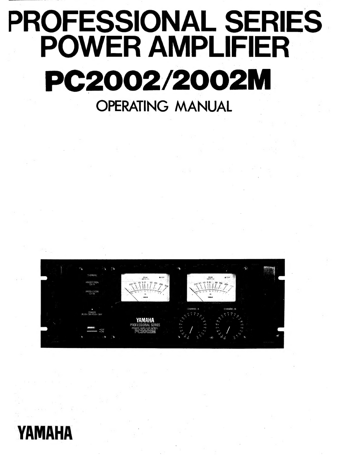
Yamaha PC2002 User manual

PET
ue
See
ee
ee
ee
PROFESSIONAL
SERIES
POWER
AMPLIFIER
PC2002/2002M
OPERATING
MANUAL
THEAMAL
2
FEN
eas
m
“ум.
D
ym
е
о
10:
50
2
P
PO
ор
2
as
PROTECTION
510.
60
СНА
gover
19
90
2
ММА
АИ
PROTECTION
©
VIDT,
CHB
4
а
pov
ot
2
15511117
M
P
”
CHANNEL
А
CHANNEL
В
и
"om.
v
ra
ZZ
за
vip,
гр
^
YAMAHA

ABOUT
THIS
MANUAL
SCOPE
The
PC2002M
is
a
system
oriented
amplifier,
made
to
be
used
in
conjunction
.with
mixers,
consoles,
frequency
dividing
networks
and
speakers
—
those
made
by
Yamaha
or
by
other
manufacturers.
Like
any
power
amplifier,
the
PC2002M’s
performance
depends
on
system
design
and
installation,
in
addition
to
its
own
capabilities.
Thus,
the
PC2002M
Operating
Manual
is
system
oriented,
describing
system
design
parameters
and
installation
techniques,
as
well
as
operation
and
performance
of
the
PC2002M.
ORGANIZATION
We
recommend
that
you
read
the
entire
Operating
Manual.
However,
if
you
are
using
the
PC2002M
in
an
existing
system,
and
you
are
familiar
with
high
power
amplifiers,
the
BRIEF
OPERATING
INSTRUCTIONS,
Pages
2
&
3,
contain
all
the
information
necessary
for
basic
connections
and
operation.
NOTE:
The
PC2002
is
identical
to
the
PC2002M
except
there
are
no
Peak
Reading
Meters.
CONTENTS
1МТВОООСТОМ.........................
1
BRIEF
OPERATING
INSTRUCTION
...........
2,3
GENERAL
SPECIFICATIONS
................
4
PERFORMANCE
GRAPHS
..................
5,6
A
DISCUSSION
OF
SPECIFICATIONS
........
7~9
MOUNTING
.........
SW
exp
A
M
oe
E
10
BLOCK
DIAGRAM
.......................
11
DIMENSIONS
..................
а
12

INTRODUCTION
The
PC2002M
is
not
just
"another
big
amplifier”,
it is
an
exciting
new
approach
to
high
power
sound.
Yamaha's
leadership
is
clearly
demonstrated
by
the
PC2002M's
pro-
fessional
features,
sophisticated
design,
and
uncompromis-
ing
performance.
|
:
PEAK
READING
METERS*
Instead
of
the
more
common
and
slow
responding
VU
meters,
the
PC2002M
has
PEAK
READING
METERS
that
accurately
display
a
full
five
decades
(50dB)
of
output
level.
The
peak
meters
have
large,
illuminated
faces
marked
with
dB
and
with
watts
into
8
ohms.
The
fast
responding
meters
provide
a
better
way
to
see
the
program
dynamics,
the
transient
power
demands
placed
on
the
system,
and
the
available
headroom.
By
indicating
headroom,
the
meters
help
the
operator
avoid
over-driving
the
system,
thereby
preventing
the
“clipped”
waveforms
so
dangerous
to
drivers
and
loudspeakers.
:
CALIBRATED
INPUT
ATTENUATORS
The
PC2002M
has
log-linear
INPUT
ATTENUATORS
to
complement
its
peak
reading
meters.
The
input
attenuators
are
marked
in
20dB-calibrated.
steps,
detented
for
extra
accuracy.
The
attenuators
provide
a
smooth,
noise
free
transition
from
the
highest
to
the
lowest
audio
level.
dB-
calibrated
input
attenuators
have
numerous
advantages:
on
the
road,
they
allow
predictable
and
repeatable
setups;
in
commercial
sound
applications,
they
allow
easy,
accurate
input
sensitivity
adjustments;
in
studios
or
discos,
they
let
operators
simultaneously
adjust
the
level
of
two
channels
(or
two
programs
on
separate
amplifiers)
with
precise
track-
ing.
INPUT
AND
OUTPUT
CONNECTIONS
INPUT
CONNECTORS
for
each
channel
include
one
“male”
and
one
"female"
XLR
connector
(BALANCED)
plus
two
parallel
phone
jacks
(UNBALANCED).
This
provides
the
flexibility
necessary
for
convenient
bridging
to
another
amplifier,
as
well
as
for
adapter-free
connection
to
almost
any
mixer,
MONAURAL
OPERATION
The
PC2002
and
PC2002M
can
easily
be
adapted
for
monaural
(BTL)
operation
by
setting
the
rear-panel
MODE
switch
to
MONO.
In
the
MONO
mode
use
the
channel
A
input
connectors
and
channel
A
attenuator
for
level
control.
The
"+"
terminal
of
the
speaker
system
is
con-
nected
to
the
channel
А
“+”
output
terminal
and
the
“—’’
terminal
of
the
speaker
system
is
connected
to
the
channel
B
"+"
output
terminal.
Leave
the
channel
A
and
B
"—"
output
(SPEAKER)
terminals
and
channel
B
input
terminals
unconnected.
SPEAKER
IMPEDANCE
IS
16
—
32
OHMS
FOR:
MONO
MODE
OPERATION..
POUR
LE
MODE
MONAURAL
—
L'IMPEDANCE
DES
HAUT-PARLEURS
EST
16
—
32
OHMS.
MODE
ое
STEREO
МОМО
INPUT
channel.
A
PERFORMANCE
The
PC2002M’s
performance
is
as
impressive
as
its
features.
At
a
sustained
output
of
240
watts
into
8
ohms
(for
each
channel),
there
is
plenty
of
punch
to
reproduce
the
power-
ful
peaks
essential
to
clean
studio
monitoring.
High
power
handling
also
makes
the
PC2002M
an
unbeatable
choice
for
live
rock
or
disco
sound
systems,
where
an
amplifier
can
really
“cook”
all
night
long.
Power
alone
is
no
virtue;
the
PC2002M
has
ultra-low
distortion,
less
than
0.0596
THD
at
full
rated
power
—
the
kind
of
low
distortion
that
is
un-
detectable
by
even
the
most
critical
listeners.
A
high
damping
factor
of
better
than
350
at
1kHz
reduces
the
tendency
for
speaker
cone
overshoot,
giving
tighter
and
better
defined
bass
response.
On
the
other
end,
the
PC2002M's
frequency
response
extends
well
beyond
50kHz,
enabling
it
to
accurately
reproduce
the
most
complex
musical
waveforms
—
even
the
tortuous
output
of
today's
synthesizers.
However,
high
frequency
response
has
not
been
achieved
at
the
expense
of
stability;
in
fact,
the
PC2002M
is
rock
steady.
Even
when
connected
to
highly
reactive
multi-speaker
loads,
there
is
no
tendency
to
shut
down
or
“take
off”
into
spurious
oscillation.
MECHANICAL
CONSIDERATIONS
The
PC2002M
is
constructed
to
withstand
the
high
"G"
forces
encountered
on
the
road.
Its
solid
front
panel
mounts
in
any
standard
19-inch
rack,
and,
for
a
large
amplifier,
the
PC2002M
weighs
a
modest
44
pounds
(20.5kg).**
Front
panel
controls
and
meters
are
recessed
to
avoid
damage
or
accidental
setting
changes,
and
are
further
protected
by
a
pair
of
sturdy
carrying
handles.
Inside
and
out,
the
PC2002M
is
extremely
reliable.
Still,
should
service
ever
be
required,
the
unit
is
designed
for
easy
access.
Massive
side-mounted
heat
sinks
are
designed
for
efficient
cooling,
making
fans
unnecessary
in
all
but
the
most
severe
thermal
operating
conditions.
Four.
non-conductive
feet
ensure
proper
air
flow
when
the
amplifier
is
shelf
mounted,
and
avoid
inadvertent
ground
loops.
Multiple
protection
circuits
make
the
amplifier
nearly
abuse
proof
and
eliminate
the
need
for
troublesome
DC
power
supply
fuses.
*
The
PC2002
does
not
have
the
Peak
Reading
Meters.
**
The
PC2002
weighs
44
pounds
(20kg)

BRIEF
OPERATING
INSTRUCTIONS
e
Front
panel
ө
Rack
Handle
THERMAL
PROTECTION
CHB
Rack
Handle
|
:
|
"ew
|
|
|
5
50
зоо
in
N
|
ПИР
ДЕҢ
4
ҮР,
PEAK
ағ
WATTS
ДИ
ө
soo)
10
60
50
по
;
f
\
Мур
2
5
POWER
PUSH
ON/PUSH
OFF
YAMAHA
PROFESSIONAL
SERIES
POWER
AMPLIFIER
MODEL
@
POWER
Switch/Indicator
Pressing
this
switch
turns
power
to
the
amplifier
ON
and
causes
the
power
indicator
to
light.
Pressing
the
POWER
switch
a
second
time
turns
the
unit
OFF.
@
THERMAL
Indicator
This
indicator
lights
if
surface
temperature
of
the
main
heat
sink
exceeds
85
+
5
degrees
centigrade.
Ө
PROTECTION
Indicator
Lights
for
approximately
4
seconds
after
power
is
switched
on,
indicating
that
the
protection
circuitry.
is
active.
The
speaker
outputs
are
shut
off
while
this
indicator
is
lit.
If
the
protection
circuitry
is
activated
for
any
reason
during
amplifier
operation,
the
indicator
will
light
and
the
speaker
outputs
will
be
shut
off.
Once
the
cause
of
protection
activation
has
been
remedied
normal
operation
will
resume
automatically
and
the
protection
indicator
will
go
out.
Ө)
PEAK
Level
Meters
(PC2002M)
These
meters
have
a
rise
time
of
10
milliseconds.and
a
fall
time
of
0.8
seconds.
The
logarithmic
meter
scales
read
directly
in
watts
when
speaker
impedance
is
8
ohms.
A
dB
scale
is
also
provided
with
O
dB
referenced
at
100
watts.
211908
"RU
ust
ба
в‘
~
a?
s
CHANNEL
А
CHANNEL
В
.
9
an
8
@
Accessories
Fig.
1.
©
CLIP
Indicator
|
The
CLIP
indicators
light
when
output
distortion
of
the
respective
channel
exceeds
approximately
2%.
This
indicates
that
the
amplifier
is
clipping
due
to
excessive
input
signal
levels.
|
*The
PC2002
CLIP
indicators
are
located
above
the
input
attenuators.
О
Zero
Adjust
(PC2002M)
A
small
“*—''
screwdriver
is
used
to
adjust
the
peak
meter
zero
point.
@
Input
Attenuators
The
controls
are
detented
in
21
dB
steps,
each
step
cor-
responding
to
1
dB
of
attenuation
except
the
last
step.
Attenuation
in
the
fully
clockwise
position
is
О
dB,
and
co
in
the
fully
counterclockwise
position.
Q
Knob
Lock
Adaptors
(Supplied)
The
Knob
Lock
Adaptors
prevent
accidental
alteration
of
attenuator
settings
once
the
appropriate
settings
have
initially
been
made.

Веаг
рапе!
Cord
Reel
|)
SIEREO
МОМО
МАХАМ
SP
MRIG
USED.
CAUTION
то
REDUCE
THE
RISK
OF
ELECTRIC
SHOCK,
DO
NOT
REMOVE
COVER
HO
USER
SERVICEABLE
PARTS
INSIDE
PROT
LAMP
SOLOERED
IN
PLACE.
REFER
SERVICING
TO
QUALIFIED
SERVICE
PEAS
ATTENTION
afin
DE
RÉOUIRE
LE
RISQUE
Hi
ЕЗ
EON.
Ms
ENLEVER
LE
COUVERCLE.
IL
NE ЗЕ
TROUVE
A
СМТЕВЕУЯ
Al
POUVANT
ETRE
БЕРАНЕ
PAR
LUSAGER.
LA
LAMPE,
ТЄМОН
EST
SOUDGE
EN
PLACE.SAORESSEA
А
UN
REPARATEUR-
СОМРЕТЕ!
WARNING
то
nebuce
тне
Te
О
OF
FIRE.
г
сию
‘SHOCK,
DO
мог
EXPOSE
THIS
APPLIANCE
TO
RAN
ОН
MOISTURI
CAUTION
то
ЕЕ
due
FISK
OF
FIRE,
REPLACE
чат
SAME
TYPE
FUSE,
0
ATTENTIONS
эни
DE
А
RÉDUnE
LE
RISQUE
DE
FEU,
REMPLACE!
LUNQUEMENT
PAR
VW
FUSLE
PRIMARY
{е
7A
1250
«95,
х
US
4
Canadian
models
YAMAHA
General
model
@
SPEAKER
Output
Terminals
Fig.
2
The
red
SPEAKER
terminal
is
connected
to
the
“+”
input
©
Standard
Phone
Jacks
terminal
of
the
speaker
system
used
and
the
black
These
jacks
accept
unbalanced
input
via
standard
1/4”
SPEAKER
terminal
is
connected
to
the
"—"'
speaker
input
phone
plugs.
The
BALANCED/UNBALANCED
switch
terminal.
|
should
be
set
to
UNBALANCED
when
using
these
inputs.
These
jacks
can
also
be
used
as
send
terminals.
Ө
PIN
1GND
SW
Couples
or
decouples
the
canon
connector
earth
line
(pin
1,
о
BALANCED/UNBALANCED
Switch
shield).
Normally
ON.
In
some
cases
where
ground
loops
Determines
which
input
connectors
are
active.
In
the
cause
excessive
hum,
turning
the
ground
switch
OFF
can
BALANCED
position,
input
signals
are
accepted
via
the
interrupt
the
loop
and
reduce
the
hum.
balanced
Canon
connectors,
and
in
the
UNBALANCED
position
input
is
accepted
via
the
unbalanced
phone
jacks.
Ө
Canon
Connectors
(XLR-3-31)
These
connectors
are
generally
used
as
inputs.
Pin
1
is
@
MODE
Selector
Switch
shield,
pin
2
is
hot
and
рт
3
cold.
Compatible
connectors
Determines
whether
the
amplifier
is
to
operate
in
the
stereo
include
Canon
XLR-3-12C
and
Switchcraft
5C-1055A.
or
mono
(BTL)
mode.
©)
Canon
Connectors
(XRL-3-32)
Compatible
with
Canon’
XLR-3-11C
ог
switchcraft
5C-1056A
connectors,
these
connectors
are
useful
for
send-
ing
the
input
signal
to
other
power
amplifiers.

+ |
—
ыюъмы
‚АА
=
:
GENERAL
SPECIFICATIONS
о
а
с
POWER
OUTPUT
LEVEL
Continuous
average
sine
wave
power
with
less
than
0.05%
THD.
20
Hz
to
20
kHz.
Stereo,
8ohms.........
ip
UIS
240W
+
240W
Mone,
16
оћтѕ
....................
480W
Mono,8ohms
......................
700W
FREQUENCY
RESPONSE
10
Hz
to
50
kHz,
8ohms,
1М/............
2058
POWER
BAND
WIDTH
Stereo
8
ohms
120W
THD
ОМ
Фа
а
а
ылыы
10
Hz
to
100
kHz
Mono
16
ohms
240W
THD
0.1%
.....
ани
10
Hz
to
100
kHz
TOTAL
HARMONIC
DISTORTION
Stereo
8
ohms
120W
TkHz...................
Less
than
0.003%
Mono
16
ohms
240W
|
20
їо
20
КН2
..............
Less
than
0.007%
Mono
8
ohms
350W
201020КН2...............
Less
than
0.01%
INTER
MODULATION
DISTORTION
70
Hz
7kHz
mixed
4:
1
Stereo
8
ohms,
120W
.........
Less
than
0.01%
Mono
16
ohms,
240W
.........
Less
than
0.01%
INPUT
SENSITIVITY
Input
level
which
produces
100W
output
into
8
ohms
tate
Seg
E
A
EEES
0
dB
(0.775
V
rms)
INPUT
IMPEDANCE
Balanced
and
unbalanced
inputs,
maximum
attenuator
setting
..............
TD
25
kohms
8
OHM
DAMPING
FACTOR
КА
и
vas
vei.
Greater
than
350
201020КН2...............
Greater
than
200
S/N
RATIO
Input
shorted
at
@12.47
kHz
............
110
dB
Input
shorted
at
@IHFA
...............
115
dB
SLEW
RATE
Stereo8ohms
...................
60
V/usec
Mono
1боһтз...................
90
V/usec
CHANNEL
SEPARATION
8
ohms
120W
ТКН
pM
Mn
TL
95
dB
8
ohms
120W
201020КН2,............
MORE
80
dB
RELAY
MUTING
TIME
42
From
power
on
...................
have
4
14
sec
INDICATORS
РОМЕ
ON
и
Cosy
Дыл
АКУ
шга
кылы
LED
Protection
(Relay
OFF)
..................
LED
Thermal
Overload
(85
+
5
degrees
C)
.........
LED
Clipping
(2%
THD)
................
шил
ТЕР
Peak
Power
Meters
(PC2002M
only)
. .
.
—50
dB
to
+50
dB
range
O
dB
=
100W
into
8
ohms
FRONT
PANEL
CONTROLS
Power
буйсн...............
Push-ON/Push-OFF
Input
Attenuators
(one
per
channel)
гэгээ
22
detent
positions
in
—1
dB
steps
(0,
—1,—2...-—20,
®)
REAR
PANEL
CONTROLS/CONNECTORS
Mode
switch
.................
STEREO/MONO
Pin
1
GND
Switch
(XLR
connectors)
,.....
ON/OFF
Balance/Unbalance
Switch
.....
BALANCED
(XLR)/
UNBALANCED
(PHONE)
POWER
REQUIREMENTS
U.S.
&
CANADIAN
models
...
....
AC120V,
60
Hz
GENERAL
Model.........
АС220/240\,
50/60
Hz
POWER
CONSUMPTION
|
U.S.
8
CANADIAN
models
..............
700
W
GENERAL
тоде!..........
РОА
1600
W
DIMENSIONS
(үх
рхнН)...............
480
х
413
х
183
тт
(18-7/8"
х
16-1/4"
x
7-1/4”)
WEIGHT
PC2002
араа
аа
каа
Ми
20
kg
(44
pounds)
РС2002М
.................
20.5
kg
(45
pounds)
NOTE:U.S.
8:
CANADIAN
Models
must
be
operated
into
8
ohms
in
stereo
mode
and
16
ohms
in
mono
mode
in
accordance
with
safety
regulations.
All
specifications
subject
to
change
without
notice.

PERFORMANCE
GRAPHS
[27]
пина
и
1000
:
оов
$ Я
бог
Be
H
оо!
===
.
0005
=I
a
-
Г
Fig.
3
зоо
нЕ
Fig.
7
Io!
ооо!
5
^
5
LOAD
IMPEDANCE
Bor
mnm
о:
02
os
а
2
оџтрот
POWER”
so
юо
200
юм
LOAD
IMPEDANCE
VS
OUTPUT
POWER
T.H.
DISTORTION
THD
0,05%
Mode
STEREO
Load
Impedance
82
Single
Channel
Driven
Mode
STEREO
Both
Channel
Driven
IN/OUT
Channel
A
4-3-4---4-1----
Ш
[^]
м
1000
шини
шш
ишш
шша
=
ог
m
3
ЫГ
Ф
ол
|
300
|
оов
==
gro
@
|
Бо
ЕЕН
T
ЕН
Зоог
20
|
Fig.
4
9005
ю
100
шэнжэ
ЮК
(He)
ооо
"nM
Fig.
8
POWER
BAND
WIDTH
9001
са
ог ољ
t
2
5
10
20
Бо
00
200
500
(4)
Load
Impedance
162
а а
80
OUTPUT
POWER
Mode
MONO
Mode
STEREO
Load
Impedance
162
т
Both
Channel
Driven
Mode
MONO
s
E
|
|
Г
о
кај
ш
100
аша
i-
Ф
ЦЭ
йл
ШИ
i
i
ni
5
mi
BAL
IN
-5
HH
3
20
x
>
Г]
i
lo
H
|__|
Е
IN
M
:
Г
ЕЕ:
79
Fig.
5
3
+H
юго
50
00
200
бо
Ik
әк
Sk
пок
20
50к
(HD
8
2
4-4
Fig.
9
FREQUENCY
.
FREQUENCY.RESPONSE
'
105
Nm
ТОК
UR
(D
Load
Impedance
162
@
Load
Impedance
80
INPUT
IMPEDANCE
Power
Output
Power
Output
Mode
STEREO
=
1W
at
1kHz
=
1W
at
1kHz
Mode
MONO
Mode
STEREO
Channel
A
Channel
A
&
B
(UNBAL
INPUT)
(UNBAL
INPUT)
|
|
“)
НИ
1000
H
05
|
Н
500
|-|
ЕНН
3
и
ry
8
о
71717
5
04
i
2
(00
ae
Bos
FE
Е
[У
|
г
S
вю
{=
17
0.05
й
0.02
зо
'
Fig.
10
И
|||
Fig.
6
оо
100
FneluENCY
пок
(на)
9
100
re
ute
ток
(HR)
1
OUTPUT
IMPEDANCE
DAMPING
FACTOR
|
Load
Impedance
82
Load
Impedance
82
)
|
Mode
STEREO
Моде
STEREO

The
following
are
actual
oscilloscope
photographs
made
by
an
in-
dependent
testing
laboratory.
НЕЕ
~
20
Hz
Square-Wave
Response
Remarkably
accurate
response
at
this
low
frequency
ensures
that
bass
reproduction
will
be
tight
and
clean.
рүү
ИШИШ
ЕШШ
·:
:
1
kHz
Square-Wave
Response
Flawless
midrange
response
is
immediately
evident
in
this
scope
trace.
There
is
no
unnatural
response
rolloff,
ringing
or
overshoot
to
interfere
with
music
reproduction.
Ши
сн
cutn
pea
|
|
ГГ
=:
20
kHz
Square-Wave
Response
Although
20,000
Hz
is
well
beyond
the
range
of
human
hear-
ing,
the
response
accuracy
shown
here
means
that
upper-
range
harmonics
vital
to
natural
reproduction
will
be
proper-
ly
reproduced,
||
|||
шатлан
Шин
ажи
А
Мур
А
И
|
|
7
БШ
БИШ
ШИ
-.
Total
Harmonic
Distortion
with
a
1
kHz
Sine
Wave
Signal:
The
distortion
components
shown
in
this
trace
are
actually
a
mere
0.001496,
It's
this
type
of
low-distortion
performance
that
makes
the
PC2002
and
PC2002M
ideal
for
demanding
professional
applications.
VEN
BIO
Mus.
imd.
ши
ENNENNENN
=>
Total
Harmonic
Distortion
with
a
20
kHz
Sine
Wave
Signal
Although
the
amp
is
delivering
240
watts
(mono,
BTL)
output
power
continuously
at
20,000
Hz,
harmonic
distor-
tion
is
no
more
than
0.0036%.
That
means
clean,
transparent
highs,
even
on
high-level
peaks,
Kf
МУТ
|
АУ
Шимт
дани
Шинэ
шин
РИА
МЕТ
о
-<
Slew Rate
and
Rise
Time
1
Stereo
mode,
8
ohm
load
f=2
kHz
:
GOV/uS
slew
rate
шаншаннн
Шина
А
|
У
|.
шинэ
шин
АРА
УК
Мм
|
с
--
Mono
mode,
16
ohm
load,
f=2
kHz:
90V/uS
slew
rate.
BEN
Шин
HERE
ШШЕ
Е
ШШШ
1
-
Stereo
mode,
8
ohm
load,
f=1
kHz:
1.848
rise
time.
Here's
your
guarantee
of
exceptional
transient
response.
Extremely
high
slew
rate
and
fast
rise
time
mean
precise
signal
reproduction.
[1uS/horizontal
division,
20
V/vertical
division]

А
DISCUSSION
OF
SPECIFICATIONS
POWER
OUTPUT
Types
of
Power
Ratings
Peak
power
refers
to
the
maximum
undistorted
power
output
of
an
amplifier.
Most
amplifiers
cannot
sustain
their
peak
power
ratings
for
long
periods
of
time
without
external
cooling
fans.
Because
there
are
many
different
methods
of
rating
an
amplifier's
peak
power,
it
is
hard
to
objectively
compare
the
peak
power
ratings
of
two
amplifiers.
The
peak
power
rating
is
primarily
useful
for
determining
an
amplifier’s
ability
to
reproduce
the
peaks
and
transients
in
a
musical
program,
peaks
which
may
be
20dB
or
more
above
the
average
power
level.
The
ability
to
accurately
reproduce
these
high
power
peaks
in
a
musical
program
is
one
of
the
most
important
advantages
of
the
PC2002M
as
compared
to
a
smaller
power
amplifier.
“RMS”
power
is
actually
a
misnomer
for
average
power.
Average
power
is
usually
measured
with
a
sine
wave
input
signal,
and
is
equal
to
the
amplifier’s
RMS
output
voltage
squared
and
then
divided
by
the
load
impedance.
Because
RMS
voltage
is
used
in
the
formula,
the
resulting
power
rating
is
commonly
called
“RMS
power”.
While
it
means
.the
same
as
"RMS
power",
to
be
more
accurate,
the
PC2002M
is
rated
in
watts
of
"continuous
average
sine
wave
power”,
Since
the
PC2002M
is
a
professional
power
amplifier,
not
sold
for
home
hi-fi
use,
it is
not
required
to
meet
the
power
rating
standard
set
by
the
FTC
(Federal
Trade
Commis-
sion),
a
standard
meant
for
consumer
power
amplifiers.
However,
the
PC2002M
is
measured
under
severe
condi-
tions
which
simulate
the
most
demanding
professional
usage.
Thus,
the
PC2002M
would
easily
meet
the
FTC
ratings
for
consumer
amplifiers.
In
addition,
the
PC2002M
user
has
the
benefits
of
professional
features
and
reliability.
Reasons
for
a
High
Power
Amplifier
An
interesting
characteristic
of
the
human
ear
is
described
by
the
"Webe-Fechner"
law.
In
its
general
form,
the
law
applies
to
al!
our
senses:
The
amount
of
additional
stimulus
needed
to
produce
a
perceptible
change
is
dependent
on
the
amount
of
stimulus
already
present.
In
mathematical
terms,
the
Weber-Fechner
law
suggests
that
the
human
ear
responds
to
changes
in
sound
level
in
a
logarithmic
manner.
More
simply
this
means
that
for
a
sound
to
seem
twice
as
loud,
it
requires
approximately
ten
times
as
much
acoustic
power
(and
therefore
ten
times
as
much
amplifier
power).
Thus,
the
PC2002M's
high
power
output
capabilities
are
extremely
valuable.
One
of
the
other
benefits
of
high
power
output
is
the
ability
of
the
amplifier
to
easily
reproduce
high
peak
power
transients
(which
may
be
100
times
the
average
program
power,
or
even
more).
DISTORTION
(Refer
to
Figures
7
and
8.)
|
The
PC2002M
is
designed
to
have
the
lowest
possible
dis-
tortion.
There
are
many
different
forms
of
distortion,
however,
and
comprehensive
distortion
ratings
offer
a
means
to
compare
the
performance
of
different
amplifiers.
Harmonic
Distortion,
is
characterized
by
the
appearance.at
the
amplifier
output
of
harmonics
of
the
input
waveform
which
were
not
present
in
the
original
input
waveform;
Total
Harmonic
Distortion,
or
T.H.D.
is
the
sum
total
of
all
of.
these
unwanted
harmonics
expressed
as
a
percentage
of
the
total
signal.
Harmonic
distortion,
in
an
amplifier,
can
be
created
in
any
of
several
ways.
The
Т.Н.О.
rating
of
a
power
amplifier
refers
to
creation
of
unwanted
harmonics
by
the
amplifier
during
“linear”
operation
(normal
input
and
output
levels,
impedances,
etc.).
Harmonic
distortion
is
also
created
by
"clipping",
a
form
of
"non-linear"
operation,
which
occurs
when
the
signal
level
at
an
amplifier's
input
is
high
enough
to
drive
the
amplifier
beyond
its
rated
maximum
output.
The
amplifier,
in
attempting
to
reproduce
this
signal,
reaches
its
maximum
output
voltage
swing
before
it
reproduces
the
top
of
the
signal
waveforms.
Since
the
output
voltage
cannot
rise
any
farther,
the
tops
of
the
waveform
are
"squared
off’,
or
clipped.
Clipping
distortion
adds
odd
upper
harmonics
(3rd
harmonic,
5th,
etc.)
to
the
original
signal.
(Input
clipping
would
be
similar,
where
the
input
stage
of
the
amplifier
is
overdriven
by
a
high
level
input
signal.)
The
PC2002M
has
wide
input
headroom
and
extremely
high
peak
power
output
capabilities
(headroom)
to
help
avoid
the
problems
of
clipping
distortion.
Another
form
of
harmonic
distortion
that
occurs
in
some
power
amplifiers
is
called
crossover
distortion.
*
Crossover
distortion
can
be
caused
by
improper
bias
in
the
output
transistors
of
an
amplifier.
The
amount
of
crossover
distor-
tion
stays
the
same
whether
the
signal
is
large
or
small,
so
the
percentage
of
distortion
goes
down
as
the
signal
level
goes
up.
Thus,
an
amplifier
with
crossover
distortion
may
sound
relatively
distortion
free
at
high
output
levels,
yet
sound
“fuzzy”
at
low
levels.
Some
amplifiers
have
internal
adjustments
which
enable
a
service
technician
to
control
the
amount
of
output
transistor
bias,
and
therefore
control
the
distortion.
Fig.
19A
—
Large
Amplitude
Sine
Wave
with
Crossover
(notch)
Distortion.
:
D
CE
N
Fig.
19B
—
Smailer
Amplitude
Sine
Wave
with
same
amount
(higher
96)
of
Crossover
(notch)
Distortion.
*"Crossover",
in
this
case,
refers
to
the
transition
between
the
positive
half
and
the
negative
half
of
the
output
voltage
waveform
in
a
"push-pull"
class
B
or
AB
power
amplifier:
it
has
nothing
to
do
with
the
crossover
used
to
divide
frequencies
in
a
speaker
system.
See
Figure
19.

Intermodulation
Distortion,
or
I.M.
is
characterized
by
the
appearance
in
the
output
waveform
of
frequencies
that
are
equal
to
sums
and
differences
of
integral
multiples
of
two
or
more
of
the
frequencies
present
in
the
input
signal.
The
difference
between
intermodulation
distortion
апа
harmonic
distortion
is
that
two
or
more
different
fre-
quencies
must
be
present
to
produce
intermodulation
distortion
(only
one
frequency
is
needed
for.
harmonic
distortion
to
appear),
and
that
intermodulation
distortion
products
may
not
be
harmonically
related
to
the
original
frequencies.
Like
its
harmonic
distortion
figure,
the
inter-
modulation
distortion
in
the
PC2002M
is
low
enough
to
be
virtually
inaudible
even
in
the
most
critical
situations.
FREQUENCY
RESPONSE
(Refer
to
Figure
5)
The
frequency
response
of
the
PC2002M
describes
the
variation
in
its
output
signal
level
with
frequency
when
the
input
signal
is
held
constant.
The
extremely
"'flat"
frequen-
cy
response
curve
of
the
PC2002M
is
an
indication
of
its
overall
quality
and
its
ability
to
respond
to
upper
and
lower
harmonics
of
signals
all
the
way
to
the
extremes
of
the
.
audio
spectrum.
Because
extreme
stability
is
necessary
for
some
types
of
commercial
sound
applications,
some
manufacturers
restrict
frequency
response
or
allow
relatively
high
distortion
in
return
for
increased
amplifier
stability.
The
PC2002M,
on
the
other
hand,
has
excellent
frequency
response
and
ultra-
low
distortion,
yet
is
inherently
stable
under
the
most
difficult
loads,
even
in
the
"mono"
mode.
The
frequency
response
of
the
PC2002M
has
been
inten-
tionally
limited,
however,
at
very
low
frequencies
(sub-
audio).
Because
of
this,
severe
low
frequency
transients,
or
DC
offset,
appearing
at
the
input
to
the
PC2002M
are
unlikely
to
damage
a
speaker
load.
Other
amplifiers
which
are
DC
coupled
throughout
may
have
a
"'flatter''
sub-audio
frequency
response,
but
this
makes
them
capable
of
ampli-
fying
dangerous
DC
input
voltage
or
sub-audio
transients
and
delivering
them
(at
high
power)
to
a
speaker.
POWER
BANDWIDTH
(Refer
to
Figure
4)
The
power
bandwidth
of
the
PC2002M
is
a
measure
of
its
ability
to
produce
high
power
output
over
a
wide
frequency
range.
The
limits
of
the
power
bandwidth
are
those
points
where
the
PC2002M
can
only
produce
1/2
the
power
that
it
can
produce
at
1000Hz.
While
the
frequency
response
is
measured
at
relatively
low
power
output
(1
watt),
the
power
bandwidth
is
measured
at
the
PC2002M's
full
power
output
(before
clipping).
The
power
bandwidth
of
the
PC2002M
is
quite
“Нат”,
and
extends
to
100kHz,
well
beyond
the
limits
of
the
audio
spectrum.
The
wide
power
bandwidth
of
the
PC2002M
means
that
it
can
reproduce
high
level
upper
harmonics
of
a
signal
as
easily
as
it
can
reproduce
mid-range
fundamentals.
It
means
that
you
get
full
power
performance
from
the
PC2002M
over
the
entire
audio
frequency
spectrum.
This
is
especially
important
when
the
amplifier
is
called
upon
to
reproduce
musical
material
with
high
energy
over
a
wide
frequency
range,
such
as
rock
and
roll.
CHANNEL
SEPARATION
This
specification
indicates
the
output
from
one
channel
when
a
signal
is
fed
to
the
other
channel.
The
PC2002M's
channel
separation
is
very
good,
which
means
that
even
critical
stereo
programs
will
be
unaffected
by
crosstalk
between
channels.
HUM
AND
NOISE
Hum
or
noise
from
a
power
amplifier
disrupts
a
program,
and
is
irritating
to
a
listener.
Hum
and
noise.
could
be
considered
a
form
of
distortion.
The
PC2002M's
hum
and
noise
are
so
low
that
they
are
completely
inaudible
under
any
normal
listening
circumstances.
SLEW
RATE
А
Slew
rate
is
a
measure
of
а
power
amplifier’s
ability
to
follow:
a
fast
rising
waveform
at
higher
frequencies
and
higher
power
outputs
than
the
rise
time
measurement.
It
might
seem
reasonable
to
assume
that
the
fastest
slew
rate
for
an
audio
waveform
occurs
at
20kHz.
However,
this
is
not
the
case.
When
one
frequency
is
superimposed
upon
another,
the
combined
waveform
has
a
slew
rate
that
is
greater
than
the
slew
rate
of
either
signal
by
itself.
The
actual
value
of
the
slew
rate
of
one
of
these
waveforms
(or
any
waveform)
depends
not
only
on
the
frequency,
but
on
the
amplitude
of
the
waveform
as
well.
Thus,
the
criteria
for
a
good
slew
rate
specification,
which
indicates
that
an
amplifier
can
reproduce
these
combination
waveforms,
varies
with
the
maximum
power
output
capability
of
the
amplifier.
The
higher
the
power,
the
higher
the
required
slew
rate.
With
a
60
volts/microsecond
slew
rate,
the
PC2002M
can
easily
reproduce
even
the
most
extreme
audio
waveforms
at
its
full
power
output.
INPUT
IMPEDANCE
The
input
impedance
of
the
PC2002M
is
high
enough
to
allow
it
to
be
used
with
most
semi-pro
devices,
or
to
be
used
as
a
“bridging”
load
for
а
600-ohm
source.
INPUT
SENSITIVITY
The
PC2002M's
input
sensitivity
indicates
the
input
drive
voltage
needed
for
the
PC2002M
to
produce
its
rated
output
of
240
watts
into
8
ohms
(input
attenuators
are
adjusted
to
maximum
clockwise
rotation
for
minimum
attenuation).
PROTECTION
CIRCUITS
AND
THERMAL
SPECIFICATIONS
The
PC2002M
is
one
of
the
safest
amplifiers
you
can
find.
It
incorporates
multiple
protection
circuits—transient
suppression,
current
limiting,
short
circuit
and
overload
protection,
dc
offset
sensing
with
relay
disconnect,
powered
transformer
overtemperature
sensing
with
auto
shutdown—
to
prevent
speaker
damage
in
the
event
of
an
amplifier
failure,
and
to
prevent
amplifier
damage
in
the
event
of
a
load
or
cable
problem.
Because
the
circuits
function
auto-
matically,
front
panel
LEDs
are
installed
to
inform
the
operator
of
overload
protection
status.
A
thermal
LED
also
warns
of
excessive
heat
sink
temperature.
GAIN
Gain
is
the
ratio
of
the
PC2002M's
output
voltage
to
its
input
voltage..
Maximum
gain
occurs
when
the
input
attenuators
are
set
for
minimum
attenuation.
If
the
input
and
output
voltage
are
specified
in
dB,
the
voltage
gain
is
equal
to
the
difference
of
the
two
dB
numbers.
As
stated
under
:
INPUT
SENSITIVITY,
an.
input
voltage
of
OdB
(0.775
volts)
produces
an
output
power
of
100
watts
into
an
8-ohm
load.

OUTPUT
IMPEDANCE
(Refer
to
Figure
10)
The
output
impedance
of
the
PC2002M
is
extremely
low.
Thus,
within
its
operating
limits,
the
PC2002M
is
a
good
approximation
of
a
perfect
voltage
source
and
will
deliver
increasing
power
levels
into
lower
impedance
loads
in
a
linear
fashion
according
to
Ohm’s
law.
DAMPING
FACTOR
Damping
factor
is
a.term
that
is
derived
by
dividing
the
load
impedance
(speaker
or
other
load)
by
the
amplifier's
output
impedance.
Thus,
a
high
damping
factor
indicates
a
low
output
impedance
at
as
specified
load.
The
cone/voice-coil
assembly
of
a
loudspeaker
gains
inertia
during
its
back
and
forth
movements.
This
inertia
can
cause
it
to
“overshoot”,
that
is,
to
continue
movement
in
one
direction,
even
when
the
amplifier
is
trying
to
pull
it
back
in
the
other
direction.
An
amplifier
with
a
low
output
impedance
can
"damp"
(reduce)
unwanted
loudspeaker
motions,
as
explained
below.
.
Volts
No
Voltage
3
Time
Fig.
20A
—
Speaker
Cone
at
Rest
Input
-..
Voltage
ч
From
\
Amplifier
\
1
Volts
Time
Fig.
208
—
Speaker
Cone
moved
outward
by
Positive-Going
Voltage
from
Amplifier.
Volts
“Back
EMF”
From
.
Speaker
Time
Fig.
20C
—
Voltage
from
Amplifier
has
dropped
to
Zero
but
Speaker
Cone
has
moved
back
PAST
its
rest
posi-
tion
(overshoot)
and
is
producing
a
voltage
of
its
own:
"Back
EMF”.
During
the
“overshoot”
movement,
the
voice
coil
of
the
loudspeaker
interacts
with
the
loudspeaker's
magnetic
assembly
to
produce
a
voltage
called
“back
E.M.F."
(electro-motive
force).
This
action
is
similar
to
the
opera-
tion
of
a
dynamic
microphone.
If
the
amplifier's
output
impedance
is
low,
this
"back
E.M.F.”
voltage
is
shunted
through
the
amplifier's
output
circuits
to
ground,
and
back
to
the
voice
coil.
Since
the
path
from
the
voice
coil,
through
the
amplifier's
output
circuits,
and
back
to
the
voice
coil
is
a
complete
circuit,
a
current
flows
in
the
voice
coil.
This
current,
causes
the
voice
coil
to
act
like
an
electro-magnet;
the
electro-magnet
(voice
coil)
interacts
with
the
magnetic
assembly
of
the
loudspeaker,
and
the
unwanted
overshoot
is
reduced
(a
magnetic
braking
action).
Amplifier
Fig.
21
—
Current
produced
by
“Back
EMF”
follows
path
through
Amplifier's
Output
Impedance
to
speaker-coil.
If
the
amplifier's
output
impedance
is
low
(considerably
less
than
the
impedance
of
the
loudspeaker
voice
coil),
this
damping
action
is
limited
only
by
the
resistance
of
the
voice
coil
combined
with
the
resistance
of
the
speaker
lead
wires.
While
the
value
of
a
high
damping
factor
in
reducing
cone
overshoot
is
disputed,
the
PC2002M's
high
damping
factor
is
evidence
of
good
overall
engineering
design.

MOUNTING
PHYSICAL
MOUNTING
Shelf
Mounting
The
PC2002M
can
be
used
on
any
surface,
so
long
as
there
is
adequate
ventilation.
Do
not
remove
the
PC2002M's
feet,
since
this
would
prevent
air
flow
below
the
amplifier.
Permanent
Installation
Rack
Mounting
Mount
the
PC2002M
in
any
standard
19"
electronic
equipment
rack
as
shown
to
the
right.
Leave
adequate
space
between
the
PC2002M
and
other
devices
in
the
rack
for
ventilation,
and
for
expected
cabling.
Cooling
fans
may
be
required
when
the
PC2002M
must
produce
extremely
high
average
power
output,
or
when
it
is
located
in
a
high
temperature
environment,
such
as
a
closed
outdoor
building
in
direct
sunlight.
Rack
Mounting
for
Portable
Usage
Road
cases
must
be
durable
enough
to
survive
heavy
cartage,
and
airline
travel.
Brace
the
rear
of
the
PC2002M,
and
if
the
road
case
is
small
and
ventilation
is
constricted,
install
cooling
fans.
One
possible
design
is
shown
in
Figure
7-172"
П
Ци
=
лин
И
м
9172"
——
"
Front
fan
panel
side-
view
after
folding.
»:27|
Rear
panel
after
folding.
1639
NOTE:
Brace
length
assumes
a
front-back
rack
depth
of
15“.
каа"
Left
braces
for
securing
PC2002M
т
rack,
(For
right
braces,
use
same
measurements
and
flop.)
Front
fan
panel
installed
.
Air
Air
Flow
РС2002М
Flow
х
FRONT
VIEW
A
Shelf
Shelf
mounting
Perforated
рапе!$
for
air
flow
PC2002M
РС2002М
Rear
fan
panel
installed
Fig.
22
—
PC2002M
with
Cooling
Fans
Extra
rack
strips
mounted
in
back
of
cabinet
for
mounting
special
support
brackets.
PC2002M
mounted
in
rack
showing
support
brackets
made
from
bent
pieces
of
1/8”
steel
rod
with
nuts
welded
to
their
ends.

BLOCK
DIAGRAM
SMO.LVOIQNI
әлир
азл
8-
et
оа
–
дэн
Adans
.
га)
МЗМОЧ4
L—
o-
|
790
UT
d3Mod
e
omod
poyeindon
“ЕД
-0
0-
4
=
eaup
Аврэм
зо
Bun2ejop
Оа
^
авүзүү
|
Sack
1
8:HO
У-Н
[uo
игоогоа
dno
11
луамп/луа
(
1
1
1
1
t
|
1 р
|
Bunoeyep
Е
и
лувмп/
Iva

12
DIMENSIONS
лт
436
~
1
(17-1/8")
—
-
480
(18-7/8")
UR
ШШШ
Weight:
PC2002
a
ОНЫ
n
ШШШ
ШИН
44
165
(20.0
kg)
PC2002M
45
Ibs
(20.5
kg)

Connecting
the
Plug
and
Cord
|
IMPORTANT.
The
wires
in
this
mains
lead
are
coloured
in
accordance
with
the
following
code:
BLUE
:
NEUTRAL
BROWN:
LIVE
As
the
colours
of
the
wires
in
the
mains
lead
of
this
apparatus
may
not
correspond
with
the
coloured
markings
identifying
the
terminals
in
your
plug
proceed
as
follows:
The
wire
which
is
coloured
BLUE
must
be
connected
to
the
terminal
which
is
marked
with
the
letter
N
or
coloured
BLACK.
The
wire
which
is
coloured
BROWN
must
be
connected
to
the
terminal
which
is
marked
with
the
letter
L
or
coloured
RED.
SERVICE
The
PC2002,
PC2002M
are
supported
by
Yamaha's
worldwide
.
network
of
factory
trained
and
qualified
dealer
service
personnel.
In
the
event
of
a
problem,
contact
your
nearest
Yamaha
dealer.

_
YAMAHA
YAMAHA
CORPORATION
PO.Box
1,
Hamamatsu,
Japan,
үб69300.
Е
;
OMD-54
|
8811
M
Ф
Printed
in
Japan.
Other manuals for PC2002
1
This manual suits for next models
1
Table of contents
Other Yamaha Amplifier manuals

Yamaha
Yamaha CX-1 User manual

Yamaha
Yamaha YST-A5 User manual

Yamaha
Yamaha A-S3000 User manual

Yamaha
Yamaha C-45 User manual

Yamaha
Yamaha AX-390 User manual

Yamaha
Yamaha A-S501 User manual

Yamaha
Yamaha P1000S User manual

Yamaha
Yamaha DSP-A595 User manual

Yamaha
Yamaha TX4n User manual

Yamaha
Yamaha M-35 User manual

Yamaha
Yamaha XP7000 User manual

Yamaha
Yamaha KMA-1080 User manual

Yamaha
Yamaha CX-600 User manual

Yamaha
Yamaha DSP-A5 User manual

Yamaha
Yamaha Sessioncake SC-01 User manual

Yamaha
Yamaha BX-1 User manual

Yamaha
Yamaha BBT 500H User manual

Yamaha
Yamaha KA-M555 User manual

Yamaha
Yamaha PD2500 User manual

Yamaha
Yamaha A-S801 User manual