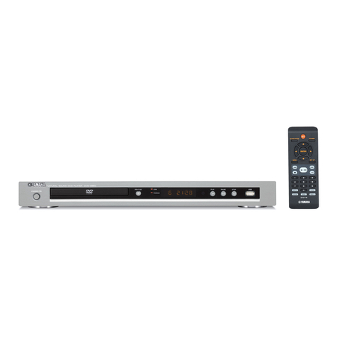
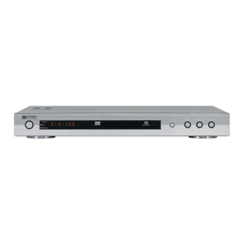
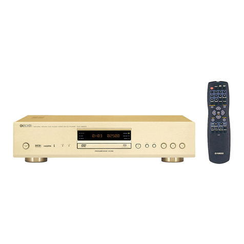
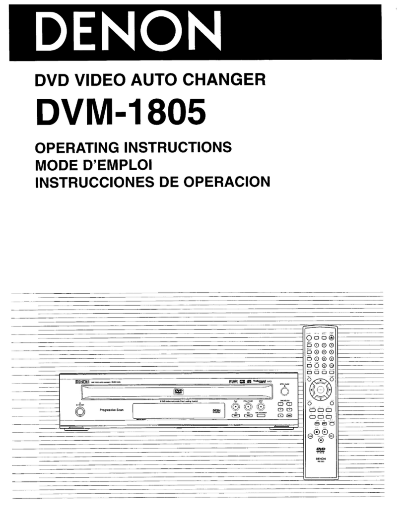
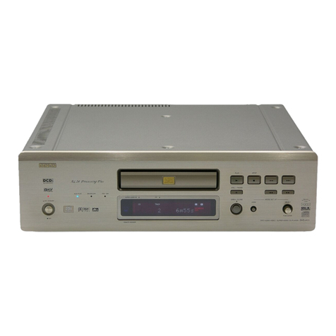
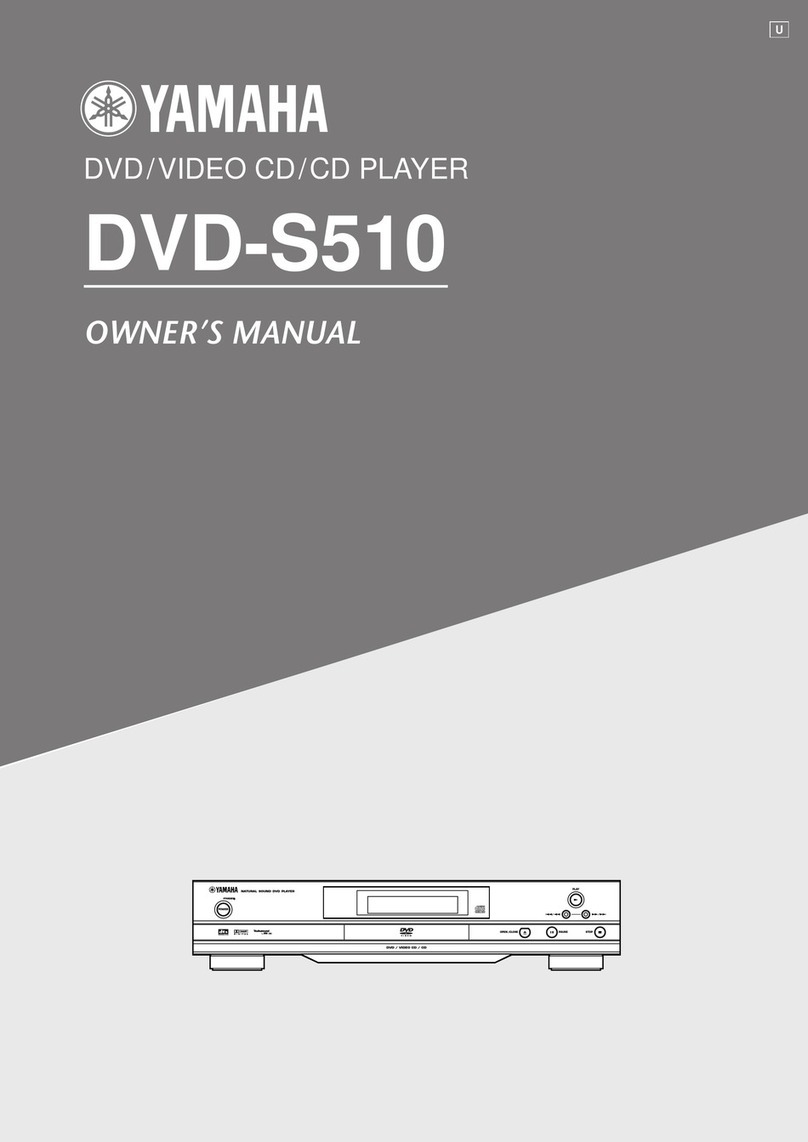
Yamaha DVD-C961 User manual

eYAMAHA
DVD AUDIONIDEO SA-CD CHANGER
DVD-C961
OWNER'S
MANUAL
-..
• -
,..
.-
,~--
...
r'
.~
.
•
YAMlAII
~
JL
..-
@
~-
~
CO>
e0 0 e.
1--
---I
@@~
~~O
o
--
I I
._-
-_.
~
@
rnJO§~
AUDIO/VIDEO
SUPERAUDIOCD
[DIGITAL
VIDEO)
eYAMAHA
DVD AUDIONIDEO SA-CD CHANGER
DVD-C961
OWNER'S
MANUAL
-..
• -
,..
.-
,~--
...
r'
.~
.
•
YAMlAII
~
JL
..-
@
~-
~
CO>
e0 0 e.
1--
---I
@@~
~~O
o
--
I I
._-
-_.
~
@
rnJO§~
AUDIO/VIDEO
SUPERAUDIOCD
[DIGITAL
VIDEO)

IMPORTANT
SAFETY
INSTRUCTIONS
Serial No.:
1Read these instructions.
2Keep these instructions.
3Heed all warnings.
4Follow all instructions.
5Do not use this apparatus near water.
6Clean only with dry cloth.
7Do not block any ventilation openings. Install
in
accordance with the manufacturer's instructions.
8Do not install near any heat sources such as
radiators, heat registers, stoves, or other apparatus
(including amplifiers) that produce heat.
9Do not defeat the safety purpose
of
the polarized
or
grounding-type plug. Apolarized plug has two
blades with one wider than the other. Agrounding
type plug has two blades and athird grounding
prong. The wide blade or the third prong are
provided for your safety.
If
the provided plug does
not fit into your outlet, consult an electrician for
replacement
of
the obsolete outlet.
10
Protect the power cord from being walked on or
p;ncheJ particularly at the plugs, convenience
receptacles, and the point where they exit from the
apparatus.
11 Only use attachments/accessories specified by the
manufacturer.
12
Use only with the cart, stand, tripod,
bracket, or table specified by the
CI
manufacturer,
or
sold with the
apparatus. When acart
is
used, use
caution when moving the cart!
apparatus combination to avoid injury
from tip-over.
13
Unplug this apparatus during lightning storms
or
when unused for along periods
of
time.
14
Refer all servicing to qualified service personnel.
Servicing is required when the apparatus has been
damaged in any way, SUCil as power-supply cord
or
plug
is
damaged, liquid has been spilled or objects
have fallen into the apparatus, the apparatus has
been exposed to rain
or
moisture, does not operate
normally, or has been dropped.
15
Be sure to allow spaces
of
at least 2.5
cm
(I
inch)
above, behind and on both sides
of
this unit.
16
Do not place the following objects on this unit:
Avessel with water
in
it.
If
the vessel falls by
vibrations and water spills,
it
may cause damage to
the unit, and/or you may get an electric shock.
Apparatus shall not be exposed to dripping
or
splashing.
RISK
OF
ELECTRIC
SIIOCK
00
lOT
OPEIl
The lightning flash with arrowhead
symbol, within an equilateral triangle, is
intended to alert you to the presence
of
uninsulated "dangerous voltage" within the
product's enclosure that may be
of
sufficient magnitude to constitute arisk
of
electric shock to persons.
The
e~chunation
pojl\twUbin
an
.
equilateral triangle is intended to alert you
to the presence
of
important operating and
maintenance (servicing) instructions in the
literature accompanying the appliance.
CAUTION:
TO
REDUCE
THE
RISK
OF
ELECTRIC
SHOCK,
DO
NOT
REMOVE
COVER
(OR
BACK).
NO
USER-SERVICEABLE
PARTS
INSIDE.
REFER
SERVICING
TO
QUALIFIED
SERVICE
PERSONNEL.
MODEL:
The serial number
is
located on the rear
of
this unit.
Retain this 9wner's manual
in
asafe place for future
refere·nce.
IMPORTANT
Please record the serial number
of
this unit in the
space below.
•Explanation
of
Graphical Symbols
IMPORTANT
SAFETY
INSTRUCTIONS
Serial No.:
1Read these instructions.
2Keep these instructions.
3Heed all warnings.
4Follow all instructions.
5Do not use this apparatus near water.
6Clean only with dry cloth.
7Do not block any ventilation openings. Install
in
accordance with the manufacturer's instructions.
8Do not install near any heat sources such as
radiators, heat registers, stoves, or other apparatus
(including amplifiers) that produce heat.
9Do not defeat the safety purpose
of
the polarized
or
grounding-type plug. Apolarized plug has two
blades with one wider than the other. Agrounding
type plug has two blades and athird grounding
prong. The wide blade or the third prong are
provided for your safety.
If
the provided plug does
not fit into your outlet, consult an electrician for
replacement
of
the obsolete outlet.
10
Protect the power cord from being walked on or
p;ncheJ particularly at the plugs, convenience
receptacles, and the point where they exit from the
apparatus.
11 Only use attachments/accessories specified by the
manufacturer.
12
Use only with the cart, stand, tripod,
bracket, or table specified by the
CI
manufacturer,
or
sold with the
apparatus. When acart
is
used, use
caution when moving the cart!
apparatus combination to avoid injury
from tip-over.
13
Unplug this apparatus during lightning storms
or
when unused for along periods
of
time.
14
Refer all servicing to qualified service personnel.
Servicing is required when the apparatus has been
damaged in any way, SUCil as power-supply cord
or
plug
is
damaged, liquid has been spilled or objects
have fallen into the apparatus, the apparatus has
been exposed to rain
or
moisture, does not operate
normally, or has been dropped.
15
Be sure to allow spaces
of
at least 2.5
cm
(I
inch)
above, behind and on both sides
of
this unit.
16
Do not place the following objects on this unit:
Avessel with water
in
it.
If
the vessel falls by
vibrations and water spills,
it
may cause damage to
the unit, and/or you may get an electric shock.
Apparatus shall not be exposed to dripping
or
splashing.
RISK
OF
ELECTRIC
SIIOCK
00
lOT
OPEIl
The lightning flash with arrowhead
symbol, within an equilateral triangle, is
intended to alert you to the presence
of
uninsulated "dangerous voltage" within the
product's enclosure that may be
of
sufficient magnitude to constitute arisk
of
electric shock to persons.
The
e~chunation
pojl\twUbin
an
.
equilateral triangle is intended to alert you
to the presence
of
important operating and
maintenance (servicing) instructions in the
literature accompanying the appliance.
CAUTION:
TO
REDUCE
THE
RISK
OF
ELECTRIC
SHOCK,
DO
NOT
REMOVE
COVER
(OR
BACK).
NO
USER-SERVICEABLE
PARTS
INSIDE.
REFER
SERVICING
TO
QUALIFIED
SERVICE
PERSONNEL.
MODEL:
The serial number
is
located on the rear
of
this unit.
Retain this 9wner's manual
in
asafe place for future
refere·nce.
IMPORTANT
Please record the serial number
of
this unit in the
space below.
•Explanation
of
Graphical Symbols

FCC INFORMATION (for US customers)
I. IMPORTANT
NanCE:
DO NOT MODIFY THIS UNIT!
This product, when installed as indicated in the instructions contained
in
this manual, meets FCC requirements.
Modifications not expressly approved by Yamaha may void your authority, granted by the FCC, to use the product.
2.
IMPORTANT: When connecting this product to accessories and/or another product use only high quality shielded
cables. Cable/s supplied with this product MUST be used. Follow all installation instructions. Failure to follow
instructions could void your FCC authorization to use this product
in
the USA.
3. NOTE: This product has been tested and found
to
comply with the requirements listed
in
FCC Regulations, Part
15
for
Class "B" digital devices.
Compliance with these requirements provides areasonable level
of
assurance that your use
of
this product
in
aresidential
environment will not result
in
harmful interference with other electronic devices. This equipment generates/uses radio
frequencies and, if not installed and used according to the instructions found
in
the users manual, may cause interference
harmful to the operation
of
other electronic devices. Compliance with FCC regulations does
not
guarantee that interference
will
not
occur
in
all installations. If this product
is
found to
be
the source
of
interference, which can be determined
by
turning the product "OFF" and "ON", please try to eliminate the problem
by
using one
of
the following measures:
Relocate either this product or the device that
is
being affected
by
the interference.
Utilize power outlets that are
on
different branch (circuit breaker or fuse) circuits or install
AC
line filter/s.
.
In
the case
of
radio orTV interference, relocate/reorient the antenna. If the antenna lead-in
is
300 ohm ribbon lead, change
the lead-in to coaxial type cable.
If these corrective measures do not produce satisfactory results, please contact the local retailer authorized to distribute this
type
of
product. Ifyou can not locate the appropriate retailer, please contact Yamaha Electronics Corp., 6660 Orangethorpe
Ave.
Buena Park, CA90622.
The above statements apply
ONLY
to those products distributed
by
Yamaha Corporation
of
America or its subsidiaries.
We
Want You
Listening
FC?r
ALifetime
Yamaha and the Electronic Industries Association's Consumer Electronics Group want you to get the most
out
of
your equipment by playing it at asafe level. One that lets the sound come through loud and clear
without annoying blaring
or
distortion -and, most importantly, without affecting your sensitive hearing.
Since hearing damage from loud sounds
is
often undetectable until it
is
too late, Yamaha and the Electronic
Industries Association's Consumer Electronics Group recommend you to avoid prolonged exposure from
excessive volume levels.
CAUTION
Use
of
controls
or
adjustments
or
performance
of
procedures
other
than
those
specified
herein
may
result
in
hazardous
radiation
exposure.
LASER SAFETY
This
unit
employs
alaser.
Due
to
possible
eye
injury,
only
a
qualified
service
person
should
remove
the
cover
or
attempt
to
service
this
device.
DANGER
This
unit
emits
visible
laser
radiation
when
open.
Avoid
direct
eye
exposure
to
beam.
When
this
unit
is
plugged
into awall
outlet,
do
not
place
your
eyes
close
to
the
opening
of
the
disc
tray
and
other
openings
or
look
inside.
CAUTION
VISIBUl
AND
lNVISIBUl
LASeR
RADIATION WHEN
OPPN.
AVOID
EXPOSURE TO BEAM
ADVARSEL
SYNUO
00
USYNUO
LASI!RS11<AuNoVED ABNINO
UNDOA
UDS£1TELSE
FOR
sTIlkINo
ADVARSEL
SYNUO
00
USYNUO
LASERSTIlkINO
NAB DEKSEL
APNBS
UNNoA
EKSPONERINO FOR s11<ALEN
VARNING
SYNUO
OCH
OSYNUO
LASI!RS11lALNINO NAB
DENNA DEL AB OPPNAD BETRAKTA
EJ
s11<ALEN
VARO! AVAITAESSAOLET
ALTIlINANAKYVAu.EJA
NAKYMA1TOMAIn!
LASeR
sATEILYLLE, ALA KATSO
sArnESEEN
VORSICHT
SICHI'BARJl UNO UNSICHl'BARJl LASERSTIlAIILUNO
WENN
ABDECKUNG
GEOFFNET
MOrT.oEM STRAIn.
AUSSETSEN
DANGER
VISIBUl
AND
!NvIsIBUlLASeR
RADlAnON
WHEN
OPEN AVOID
DIREcr
EXPOSURE
TO
BEAM
ATI'ENTION
RAYONNEMENr
LASeR
VISIBUl
BY
lNVISlBUl
EN
CAS D'OUVER1URE
EXPOSmON
DANGERBUSI!.
AU
FAISCEAU
CLASS 1LASER PRODUCT
LASER KLASSE 1PROOUKT
LUOKAN 1LASERLAfTE
KLASS 1LASER APPARAT
PRODUrr
lASER
DE
CLASSE 1
Semiconductor
laser
GaAlAs
650
nm(DYD)
780
nm
(YCD/CD)
7
mW
(DYDNCD/CD)
60
degrees
Output
Power
Beam
divergence
LASER
Type
Wave
length
ii

CAUTION:
READ
THIS
BEFORE
OPERATING
THIS
UNIT.
1
To
assure the finest performance, please read this
manual carefully. Keep it
in
asafe place for future
reference.
2Install this unit
in
awell ventilated, cool, dry, clean
place -away from direct sunlight, heat sources,
vibration, dust, moisture,
or
cold. In acabinet, allow
about 2.5 cm
(l
inch)
offree
space all around this
unit for adequate ventilation.
3Locate this unit away from otherelectrical appliances,
motors, or transformers to avoid humming sounds.
4Do not expose this unit to sudden temperature
changes from cold to hot, nor locate this unit
in
an
environment with high humidity (i.e., aroom with a
humidifier) to prevent condensation inside this unit,
which may cause an electrical shock, fire, damage
to this unit, and/or personal injury.
5Avoid installing this unit
in
alocation where foreign
objects may fall onto this unit or where this unit
may be exposed to liquid dripping
or
splashing. On
the top
of
this unit, do not place:
Other components,
as
they
may
cause damage
and/or discoloration on
the
surface ofthis unit.
-Burning objects (i.e., candles), as they may
cause fire, damage to this unit, and/or
personal injury.
-Containers with liquid
in
them, as they may
fall, spilling the liquid and causing an
electrical shock to the user and/ordamage to
this unit.
6Do not cover this unit with anewspaper, tablecloth,
curtain, etc.
in
ordernot to obstruct heat radiation.
If
the temperature inside this unit rises, it may cause
fire, damage to this unit, and/or personal injury.
7Do not plug
in
this unit to awall outlet until all
connections are complete.
8Do not operate this unit upside-down.
It
may
overheat; possibly causing damage.
9Do not use excessive force on switches, knobs and/or
cords.
10
When disconnecting the power cord from the wall
outlet, grasp the plug; do not pull the cord.
11
Do not clean this unit with chemical solvents; this
might damage the finish. Use aclean, dry cloth.
12 Use only the voltage specified on this unit. Using
this unit with ahigher voltage than specified is
dangerous and may cause fire, damage to this unit,
and/or personal injury. Yamaha will not be held
responsible for any damage resulting from use
of
this unit with avoltage other than as specified.
iii
13 Do not attempt to modify
or
fix this unit. Contact
qualified Yamaha service personnel when any
service is needed. The cabinet should never be
opened for any reason.
14 When not planning to use this unit for long periods
of
time (i.e., vacation), disconnect the
AC
power
plug from the wall outlet.
15 Be sure to read the "Troubleshooting" section on
common operating errors before concluding that
this unit is faulty.
16 Before moving this unit, press STANDBY/ON to
set the unit
in
standby mode, then disconnect the
AC
power plug from the wall outlet.
17 Install this unit near the
AC
outlet and where the
AC
power plug can be reached easily.
18 The batteries shall not be exposed to excessive heat
such as sunshine, fire
or
the like.
The unit is not disconnected from the
AC
power
"::lUlCt:
as
long as it
is
connected to the wall outlet,
evenifthis unit itself
is
turned off
by
STANDBY/ON.
This state is called the standby mode. In this state, this
unit is designed to consume avery small quantity
of
power.
FOR CANADIAN CUSTOMERS
To
prevent electric shock, match wide blade
of
plug
to wide slot and fully insert.
This Class Bdigital apparatus complies with
Canadian ICES-Om.
WARNING
TO REDUCE THE RISK OF FIRE
OR
ELECTRIC
SHOCK, DO NOT EXPOSE THIS UNIT TO RAIN
OR MOISTURE:
Be sure to place this unit on alevel surface.
If
you do not do so, the PLAYXCHANGE operation
of
this unit may not function correctly, and may damage
the disc(s) and/or this unit itself.

Introduction · 3
Region
codes
3
Supplied accessories 3
Cle .
d"
anlng
ISCS
3
Playable
disc
formats
3
Patent
information
4
Functional Overview 5
Front panel 5
Remote
control
6
Rear panel 8
Connections 9
General
notes
on
connections
9
Audio
connections
9
Digital connections 9
Analog connections
10
Video
connections
11
S-video
jack
<A>
11
Composite video
jack
<B> ::.:
..
11
Component video jacks <C>
11
HOMI
connection
12
HDMIjack
12
HDMI output
12
Other
connection
14
Remote control jacks 14
Connecting the
power
cable 14
Getting Started 15
Step 1: Inserting batteries
into
the
remote
control
15
Using the remote control
15
Step 2:
Turning
on
the Power 15
Step 3: Setting language preference 16
Setting the OSD language : :
16
Setting the audio, subtitle and disc menu
languages 16
Disc Operation 17
Basic operation 17
Selecting atrack/chapter
17
Searching backward/forward
17
Repeat/Shuffle
functions
18
Repeat playback
18
Repeating asection within achapter/track
18
Shuffle playback (except DVDIVCD/SVCD)
19
Contents
Preview
functions
(OVDNCD/SVCD/CD) 19
Previewing DVD/VCD/SVCD
19
Previewing CD 20
Previewing VR format 20
On-screen
display
(OSO)
functions
(OVDNCD/SVCO/CO) 20
Selecting the title/chapter/track .
(DVDIVCD/SVCD)
21
Searching for atime (DVDIVCD/SVCD)
21
Selecting the audio/subtitle/angle (DVD)
21
Selecting the repeat mode and time display
(DVDIVCD/SVCD)
21
Selecting the title/group and searching
for atime (DVD-Audio)
21
Selecting the time display (CD) 22
Operations
for
video playback
(DVD-VideoNCD/SVCD) 22
Playback in slow motion 22
Frame-by-frame playback
.(DVD-VideoIVCD/SVCDlDivX®) 22
Zooming pictures iniout :
22
Resuming playback from the last stopped point...22
Special OVO-Video features 23
Using the disc menu
23
Selecting the camera angle ,
23
Selecting the audio language/format and
subtitle language 23
Special VCD/SVCD features
23
Using the playback control (PBC) menu 23
Special DVD-Audio features 24
Changing pages 24
Playing bonus groups 24
Special SA-CD features 24
Changing the playback layer and area 24
Playing data
discs
(MP3IWMAlJPEGI
DivXQ!)
25
Selecting afolder and track/file 25
Special picture
disc
features
25
Using the preview function 25
Zooming pictures in 26
Rotating pictures (JPEG) 26
Selecting scan effect (JPEG) 26
Playing MP3 music and IPEG pictures
simultaneously 26
Special
DivXQ!)
features 26
Using the interactive menu 26
Selecting the audio/subtitle language 26
1En

Contents
Setup Menu 27
Menu overview 27
Setup menu operation 28
General setup menu 28
Selecting DVD-AudiolVideo mode 28
LockinglUnlocking the disc for viewing 29
Programming tracks and discs 29
OSD language 30
Turning the screen saver on/off.. .30
Setting the sleep timer 30
Turning the auto standby function on/off..
31
Displaying the DivX® VOD registration
code
31
Audio setup menu
31
Setting the analog output..
.31
Setting the digital output 32
Setting the
HDMI
audio output 32
Turning the speaker setup on/off 32
Setting the speaker channels 33
S. h
CD
I'
':"'..,
'ettlng t e upsamp mg :
..
:
L"
Turning the night mode on/off 34
Video setup menu 34
Setting acolor system for your
TV
34
Setting the TV display 35
Turning the black level on/off 35
Turning the closed caption on/off 35
Adjusting the picture settings 36
Adjusting the advanced picture settings 36
Turning the progressive scan function on/off 38
Preference setup menu 38
Audio, subtitle, disc menu 38
Restricting playback with parental control.. 38
Selecting the PBC (playback control)
function 39
Selecting the MP3/JPEG menu 39
Selecting playback
of
VR format 39
Changing the password 39
Displaying DivX® external subtitle files 40
Resetting the system .40
2En
Language Codes
41
Troubleshooting 42
Glossary 44
Specifications 46

Introduction
Thank you for purchasing this unit. This
owner's manual explains the basic operation
of
this unit.
This manual is printed prior to production.
Design and specifications are subject to
change in part as aresult
of
improvements,
etc. In case
of
differences between the manual
and the product, the product has priority.
This unit is designed to support the region
management system. Check the regional code
number on the DVD disc package.
If
the
number does not match the region code
of
this
unit (see the table below or the back
of
this
unit), this unit may be unable to play the disc.
.--
Region Playable
Destination code
of
this
unit
discs
U.S.A., (I) (I)(j)
Canada
•Remote control
•Two batteries (AA, R6, UM-3) for the
remote control
•
AudioNideo
cable
•Power cable
•Owner's manual
•When adisc becomes dirty, clean it with a
cleaning cloth. Wipe the disc from the center
out. Do not wipe in acircular motion.
•Do not use solvents such as benzine, thinner,
commercially available cleaners, or
antistatic spray intended for analog records.
This unit is designed for use with discs having
the logos shown below. Do not attempt to load
any other type
of
disc into this unit.
~~~~
-
VIDEO
-
AUDIO
illJo~
~
illJo§rn
illJo~
~
DIDlTllL AUDIO
1114'
!I.mmra
IR8Wrltilblel
SUPERAUDIOCD
t£
illJo~
t£
illJDm
VIDEO
CD
IllDTllL_1 5'8
1--1
This unit can play:
•DVD-RW discs recorded in VR format
(compatible with CPRM)
•MP3, WMA and
lPEG
files recorded
on
CD-RlRW,
DVD~R1RW,
DVD+RlRW
•KODAK picture CDs, FUJICOLOR CDs
•ISO 9660 LevelilLevel2 for CD-RlRW
•Maximum 30 character display
•DivX® files recorded on CD-R/RW,
DVD-R1RW, DVD+RlRW
-Official DivX® Ultra Certified product
-Plays all versions
of
DivX® video (including
DivX® 6) with enhanced playback
of
DivX®
media files and the DivX® Media Format
.
Not."
__
1
•CD-RlRW, DVD-RlRW and DVD+RlRW/R DL
cannot be played unless finalized._
Progressive
JPEG~;na'c'opyright-proteclec
WMA
files cannot be played with this unit.
•Some discs cannot be played depending on disc
characteristics or recording conditions.
•Be sure
to
use only CD-RlRW, DVD-RlRW and
DVD+RlRW discs made
by
reliable manufacturers.
•Do not use any non-standard shaped discs
(heart-shaped, etc.).
•Do not use discs with tape, seals, paste
or
many
scratches on their surface.
•Do not use discs affixed with labels printed by a
commercially available label printer.
•For details about playable formats, see
"Specifications" on page 46.
3En

Introduction
D[]
IDOLBYl
DIGITAL
PRO
LOGIC
n
Manufactured under license from Dolby Laboratories. "Dolby", "Pro Logic" and the double-D symbol are
trademarks
of
Dolby Laboratories.
~db
Digital
Surround
"DTS" and
HDTS
Digital Surround" are registered trademarks
of
DTS, Inc.
I
DIVX
.U
L'~
Rl=l
DivX, DivX Ultra Certified, and associated logos are trademarks
ofDivX,
Inc. and are used under license.
!DCDfMI
byFAROUDJA
"DCDi"
is
atrademark
of
Faroudja, adivision
of
Genesis Microchip, Inc.
Horn.
HDMI, the HDMI logo and High Definition Multimedia Interface are trademarks or registered trademarks
of
HDMI Licensing LLC.
This product incorporates copyright protection technology that is protected by method claims
of
certain
U.S. patents and other intellectual property rights
owrie<.l
:Gy
M4crovision Corporatiol: and other rights
owners. Use
of
this copyright protection technology must be authorized by Macrovision Corporation, and
is
intended for home and other limited viewing uses only unless otherwise authorized
by
Macrovision
Corporation. Reverse engineering or disassembly
is
prohibited.
4En

Functional Overview
!±
.YAMAHA
~
.J!.. ..-..... @
............
.-
1~tI
I
f11
!I-I=Ii
I0. . ee e t
,e::::
4
1Disc tray
Loads
up
to 5discs in the disc tray.
2
~
Opens
or
closes the disc tray.
3STANDBY/ON
Turns on this unit
or
sets it to the standby mode.
4DISC 1-5 indicators
Select and directly play back the preferred disc.
Each indicator lights up
in
green when this unit
recognizes that the corresponding disc has been
loaded.
5SA-CD indicator
Lights
up
when the unit detects SA-CD signals
(see page 24).
6MULTI CH indicator
Lights up when you play multi-channel audio
source.
7DVD-AUDIO indicator
Lights up when the unit detects DVD-Audio
signals (see page 29).
8Front panel display
Shows the current status
of
this unit.
9AUDIO DIRECT indicator
Lights up when you selectthe audio direct mode
by pressing AUDIO DIRECT on the remote
control (see page 7).
oDOWN MIX indicator
Lights up when playing the disc that allows
down mixing
of
the DVD-Audio multi-channel
source (see page 10).
qHDMI indicator
Lights up when an HDMI component is
connected, and signals output via the HDMI
jack
of
this unit.
w
J<J<I/<I<J
Moves to the previous (or top
of
the currently
playing) chapter
or
track.
Searches backward.*
e
[>[>
It>t>t
Moves to the next chapter
or
track.
Searches forward.*
r[>/00
Starts
or
pauses playback.
to
Stops playback.
YPLAYXCHANGE
Reloads
or
unloads discs without interrupting
current disc playback (see page 17).
*Press and hold the button for about two seconds.
5En

Functional Overview
POWER
(I)
Turns on this unit.
2SUBTITLE
Selects the subtitle language (see pages 23 and
26).
3AUDIO
CD
®Selects the audio language
or
format (see
pages 23 and 26).
®@Changes the SA-CD playback layer (see
®@page 24).
~
@
@4PLAY
(~)
Starts playback.
®
@)
(jj
@5
STOP(_
)
®@Stops playback.
96SHUFFLE
Accesses or exits from the shuffle mode (see
@@page 19).
@@7SCAN
Previews the content
of
achapter/track
or
whole
disc (DVDNCD/SVCD) (see page 19).
Plays the first 6seconds or less
of
each track
(CD) (see page 20).
@@8TOP MENu/RETURN
Displays the top-level disc menu (DVD).
Moves back to the previous menu (VCD) (see
page 23).
9
<t4/~/.'
Selects an item
in
the currently displayed menu.
Search
or
slow playback.
ENTER
Confirms
th~
menu selection.
0MENU
Displays the menu
of
adisc (DVD/JPEG) (see
pages 23 and 25).
Switches PBC on or
off
(VCD/SVCD) (see
page 23).
6En

qAUDIO DIRECT
Turns
off
the video output during audio disc
(CD/DVD-Audio/SA-CD) playback in order to
improve audio quality. Press again to tum on the
video output.
This function is not available for HDMI output.
In the AUDIO DIRECT mode, the front panel
display dims to
"MODE
2".
N,Pt.t!fJ
•
You
can tum on
or
off
the AUDIO DIRECT mode
only when playing back CD, DVD-AUDIO,
or
SA-CD disc.
•The AUDIO DIRECT mode is canceled when
you set this unit to the standby mode.
wNumeric buttons (0-9)
Selects numbered items in the currently
displayed menu.
ePAGE
Selects the DVD-Audio still picture (see
page 24).
rSTANDBY
(c!»
Sets this unit to the standby mode.
tANGLE
Selectsthe
DVD
cameraangle (see page 23) and
scan effect for JPEG (see page 26).
YZOOM
Enlarges
or
lessens the video image (see
pages 22 and 26).
uSKIP
(1-'1I
.....
,
~~I)
Moves to the previous (top
of
the currently
playing)/next chapter
or
track.
Searches backward/forward (see page 17).*
PAUSE (
..
)
Pauses playback temporarily.
Frame-by-frame playback.
oREPEAT
Accesses
or
exits from the repeat mode (see
page 18).
PA-B
Repeats aspecific segment (see page 18).
aON SCREEN
Accesses
or
exits from the on-screen display
(OSD) menu during playback (see page 20).
Functional Overview
sSETUP
Accesses
or
exits from the setup menu
of
this
unit (see page 28).
dSOUND MODE
Selects asound mode: stereo, virtual surroundor
multi-channel.
Changes the SA-CD playback area (see
page 24).
fDIMMER
Selects from three different levels
of
brightness
for the front panel display:
MODE
1:
70% brightness
MODE
2:
40% brightness and all the indicators
on the front panel tum off.
NORMAL: 100% brightness
gDISC 1-5
Selects and directly plays backthe preferreddisc
(see page 17).
hDISC SKIP
Selects another disc (see page 17).
*Press and hold the button for about two seconds.
7En

Functional Overview
5
61
__
71
__
J~
1AUDIO
OUT
(6CH DISCRETE) jacks
Connect to the 6-channel inputjacks
of
your
AV
receiver (see page 10).
7REMOTE CONTROL (RS-232C) terminal
Use
as
an expansion terminal for commercial use.
Consult your dealer for details.
2
3
4
5
6
AUDIO
OUT
(MIXED 2CH) jacks
Connect to the audio input jacks
of
your
AV
receiver
or
stereo system
(se.e
page 10).
DIGITAL
OUT
(COAXIAL) jack .
Connect to the coaxial input
jack
of
your
AV
receiver (see page 9).
DIGITAL
OUT
(OPTICAL) jack
Connect to the optical input
jack
of
your
AV
receiver (see page 9).
REMOTE
CONTROL
(ON, OFF) switch
Switches the remote control on
or
off.
When using REMOTE CONTROL (IN, OUT)
jacks
or
REMOTE CONTROL (RS-232C)
terminal, set this switch to ON.
REMOTE
CONTROL
(IN, OUT) jacks
Connect to the remote control outputlinputjack
of
your Yamaha
AV
receiver/component (see
page 14).
8AC inlet
Connect the supplied powercable (see page 14).
9
~
VIDEO
OUT
(S VIDEOj
jack
Connect to the S-video input
jack
of
your
AV
receiver (see page 11).
oVIDEO
OUT
(VIDEO) jack
Connect to the composite video input
jack
of
your
AV
receiver (see page
II).
qHDMI jack
Connect to the HOMI input jack
of
your HOMI
component (see page 12).
w
COMPONENT
VIDEO
OUT
(Y, Pe,
PR)
jacks
Connect to the component input jacks
of
your
AV
receiver (see page
II).
..
'
N«itii
j
_
..
~
Do not touch the inner pins
of
the jacks on the rear
panel
of
this unit. Electrostatic discharge may cause
permanent damage to this unit.
•RS-232C terminal
The
REMOTE
CONTROL
(RS-232C) terminal is used in custom installation.
Do
not
connect
any cables to this terminal during normal use.
8En

Be sure to tum offthis unit and unplug the
power cable before you make or change
connections.
•Depending on the component you want to
connect, there are various ways to make
connections. Possible connections are
described below.
•Refer to the manuals supplied with your
other components as necessary to make the
best connections.
•Do not connect this unit via your VCR. The
video quality could be distorted by the copy
protection system.
•Do not connectthe audio outjack
of
this unit
to the phono in
jack
of
your audio system.
This unit has digital coaxial, digital optical,
analog 6-channel discrete and analog mixed 2-
channel outputjacks. Connection depends on
the availability
of
audio jacks on your
component.
Digital connections
This unit has both coaxial and optical digital
outputjacks. Connect the DIGITAL OUT
(COAXIAL) and/or DIGITAL OUT
(OPTICAL)
jack
of
this unit to your
AV
receiver equipped with aDolby Digital, DTS,
or MPEG decoder using acommercially
available coaxial and/or optical cable.
Connections
hI.
"-
·~fi>·~
~~iJ
®<@
~
<@®<@
coo-.
""""-'L
FROHT
..
___
~/.C*If1M.II1JS
~
~
~.-n
."'>CH
~
~~~=L-~l~~
This
unit
Notes
1
•
You
need to set [DIGITAL OUTPUT] to [ALL]
(see "DIGITAL OUTPUT" on page 32).
•
If
the audio format
of
the digital output does not
match the capabilities
of
your receiver, the
receiver produces adistorted sound
or
no sound
at all. Make sure to select the appropriate audio
format from the menu screen on the disc.
Pressing AUDIO on the remote control once
or
more may change not only the audio languages
but also the audio format. The selected format
appears in the front panel display for several
seconds.
,.
•SA-CD audio signais are not output at the
DIGITAL OUT jacks.
•
If
you want to enjoy Dolby Digital, DTS and
MPEG format, you must connect this unit to an
AV
receiver that supports these formats.
9En

Connections
Analog connections
This unit has two types
of
analog output jacks.
•6-channel discrete jacks
If you want to reproduce multi-channel Super
Audio CD (SA-CD) and DVD-Audio, connect
AUDIO OUT (6CH DISCRETE) jacks
of
this
unit to the corresponding input jacks
of
your
AV
receiver using commercially available
audio pin cables.
,I.
~<i\~
You
can also enjoy Dolby Digital Surround and
DTS Surround formats
if
your
AV
receiver does not
support these formats.
In this case, set [ANALOG OUTPUT] to [MULTI-
CHANNEL] (see "Setting the analog output" on
page 31).
10
En
•Mixed 2-channel jacks
Connect AUDIO OUT (MIXED 2CH) jacks
of
this unit to the corresponding input jacks
of
your audio component (such as astereo
amplifier) using the supplied audio/video
cable.
You
can connect asubwoofer to the
SUBWOOFER jack.
Multi-channel audio signals are down mixed
to 2-channel audio signals.
If
you play back a
down mix prohibited DVD-Audio, only the
front LIR channel audio is output.
,I,
~<i\~
When you play back adown mix prohibited
DVD-Audio, "NO DOWN MIX" appears
in
the
front panel display, and the DOWN MIX indicator
goes out.

If
your
AV
receiver has video outputjacks,
connect your receiver and then your
TV
so
that you can use one TV for several different
video sources (LD, VCR, etc.)
by
simply
switching the input source selector
of
your
receiver.
This unit has several types
of
video output
jacks. Use the one that corresponds to the
input jacks
of
the component to be connected.
Connections
S-video jack <A>
S-video connections achieve aclearer picture
than composite video connections by
transmitting video signals on separate wires
for luminance (Y) and chrominance (C).
Connect the VIDEO OUT (S VIDEO) jack
of
this unit to an S-video input jack
of
your AV
receiver and then to that
of
your TV using a
commercially available S-video cable.
Composite video jack <B>
Connect the VIDEO OUT (VIDEO) jack
of
this unit to avideo input jack
of
your
AV
receiver and then to that
of
your TV using the
supplied audio/video cable.
Component video jacks <C>
Component video connections achieve higher
fidelity color reproduction than S-video
connections by transmitting video signals on
separate wires for luminance (Y: green) and
chrominance
(PB:
blue,
PR:
red).
Connect the COMPONENT VIDEO OUT (Y,
PB,
PR)
jacks
of
this unit to component input
jacks
of
your AV receiver and then to those
of
your TV using acommercially available
component cable. Observe the color
of
each
jack when you make connections.
If
your receiver does not have component
output jacks, you can achieve abetter video
image by connecting the component output
,jacks
of
this unil-directly to the component
input jacks
of
your TV.
,I,
~(j\~
If
your
AV
receiver is equipped with the video
conversion function, you can connect the receiver
and your TV using the different cables from shown
above. For details, refer to the manual supplied with
your receiver.
11
En
If
your
AV
receiver has video outputjacks,
connect your receiver and then your
TV
so
that you can use one TV for several different
video sources (LD, VCR, etc.)
by
simply
switching the input source selector
of
your
receiver.
This unit has several types
of
video output
jacks. Use the one that corresponds to the
input jacks
of
the component to be connected.
Connections
S-video jack <A>
S-video connections achieve aclearer picture
than composite video connections by
transmitting video signals on separate wires
for luminance (Y) and chrominance (C).
Connect the VIDEO OUT (S VIDEO) jack
of
this unit to an S-video input jack
of
your AV
receiver and then to that
of
your TV using a
commercially available S-video cable.
Composite video jack <B>
Connect the VIDEO OUT (VIDEO) jack
of
this unit to avideo input jack
of
your
AV
receiver and then to that
of
your TV using the
supplied audio/video cable.
Component video jacks <C>
Component video connections achieve higher
fidelity color reproduction than S-video
connections by transmitting video signals on
separate wires for luminance (Y: green) and
chrominance
(PB:
blue,
PR:
red).
Connect the COMPONENT VIDEO OUT (Y,
PB,
PR)
jacks
of
this unit to component input
jacks
of
your AV receiver and then to those
of
your TV using acommercially available
component cable. Observe the color
of
each
jack when you make connections.
If
your receiver does not have component
output jacks, you can achieve abetter video
image by connecting the component output
,jacks
of
this unil-directly to the component
input jacks
of
your TV.
,I,
~(j\~
If
your
AV
receiver is equipped with the video
conversion function, you can connect the receiver
and your TV using the different cables from shown
above. For details, refer to the manual supplied with
your receiver.
11
En

Connections
HOMI jack
HOMI provides high quality digital audio and
video on asingle connection.
Connect the HOMI jack
of
this unit to an
HOMI input
jack
of
your AV receiver, and
then to that
of
your TV using acommercially
available HOMI cable.
If your receiver does not have an HOMI input
jack, you can achieve abetter video image
by
connecting the HOMIjack
of
this unit directly
to the HOMI input jack
of
your
TV.
12 En
NoteS)
•
You
need to make appropriate audio connections
if
the connected component does not input audio
signals (see "Audio connections" on page 9).
•This unit
is
not compatible with HDCP-
incompatible HDMI or DVI components.
•
You
need acommercially available HDMIIDVI
conversion cable when you connect this unit to
other DVI components. In this case, the HDMI
jack
of
this unit does not output any audio
signals.
•Do not disconnect or tum off the power
of
the
HDMIIDVI component connected to the HDMI
jack
of
this unit while data
is
being transferred.
Doing so may disrupt playback or cause noise.
,',
:lj\~
When connecting an HDMI component, refer to the
manual supplied with your component.
HOMloutput
•HOMI video output
This unit is compatible with the following
video formats: 480p/60 Hz, 576p/50 Hz,
720p/60 Hz, I080i/60 Hz, and I080p/60 Hz.
'Nq~'ii
•
You
need to set [HDMI VIDEO] (see page 37).
•Depending on the connected DVI component,
black and white in the image may not be distinct.
In that case, adjust the picture setting
of
the
connected DVI component.

Connections
•HOMI audio output
HDMIAUDIO
Audio format Analog output AUTO PCM OFF
Dolby Digital Multi Dolby Digital*1
,2
PCM Multi-channel*2
Multi-channel
StereoN
SUIT
PCM 2-channel
Dolby Digital Multi/StereoN
SUIT
Dolby Digital*1 PCM 2-channel
2-channel
DTS Multi DTS*1,2 PCM Multi-channel*2
DVD-Video Multi-channel S
tereoN
SUIT
PCM 2-channel
DTS 2-channel Multi/StereoN
SUIT
DTS*1
PCM 2-channel
MPEG Multi MPEG*1,2 PCM Multi-channel*2
Multi-channel
StereoN
SUIT
PCM 2-channel
MPEG 2-channel Multi/StereoN
SUIT
MPEG*1 PCM 2-channel
PCM 2-channel*4 Multi/StereoN
SUIT
PCM 2-channel PCM 2-channel
Multi PCM (PPCM) PCM (PPCM)
Multi-channel*2,3 Multi-channel
*2,3
Multi-channel
DVD-Audio
StereoN
SUIT
PCM (PPCM) PCM (PPCM)
2-channel*3 2-channel*3
Off
.-
..
--
....
·0-
2-channel*4 Multi/StereoN
SUIT
PCM (PPCM) PCM (PPCM)
2-channel 2-channel
CD/MP31 2-channel Multi/StereoN
SUIT
PCM 2-channel PCM 2-channel
WMAlDivX®
Multi DTS*1,2 PCM Multi-channel*2
Multi-channel
DTS-CD
StereoN
SUIT
PCM 2-channel
2-channel Multi/StereoN
SUIT
DTS*1
PCM 2-channel
VCD 2-channel Multi/StereoN
SUIT
PCM 2-channel PCM 2-channel
Multi MPEG*1,2 PCM Multi-channel*2
Multi-channel
SVCD
StereoN
SUIT
PCM 2-channel
2-channel Multi/StereoN
SUIT
MPEG*1 PCM 2-channel
Multi-channel area Multi PCM PCM
SA-CD Multi-channel*2,5 Multi-channel*2,5
Stereo area
StereoN
SUIT
PCM 2-channel*5 PCM 2-channel*5
~
._-
'oj:
If
the connected HDMI component does not support bitstream signals (Dolby Digital, DTS, and MPEG), the
audio output is automatically changed from bitstream signals to PCM signals.
*2:
If
the connected HDMI component does not support multi-channel audio signals, the audio output
is
automatically changed from PCM multi-channel signals to PCM stereo signals and 48
kHzll6
bits signals
or
less.
*3:
If
the audio source is prohibited downmixing, the front
UR
channel audio and 48 kHzl
16
bits signals or less are
output instead
of
downmixed stereo.
*4:
If
the connected HDMI component does not support more than 48 kHz, the audio output
is
automatically
changed to 48 kHzl
16
bits signals
or
less.
*5:
If
the connected HOMIcomponent does not support the copy control information on disc, HDMI audio is
muted and "AUDIO CANNOT BE OUTPUT FROM HDMI" appears on the bottom
of
the SA-CD menu.
Note]
You
need
to
set
[HDMI
AUDIO
OUT]
(see
page
32).
13
En

Connections
Remote control jacks
This unit has remote control input/output
jacks.
If
your
AV
receiver is aYamaha product
and has the capability to transmit
of
SCENE
control signals, you can use the SCENE
function.
Connect the REMOTE CONTROL (IN) jack
of
this unit to aremote control output jack
of
your receiver using acommercially available
monaural mini-jack cable so that this unit
starts playback automatically
by
simply
pressing abutton
of
your receiver.
When using the REMOTE CONTROL (IN,
OUT) jacks, set the REMOTE CONTROL
(ON, OFF) switch to ON.
•For details about the SCENE function, refer to
the owner's manual supplied with your Yamaha
AV
receiver.
•The REMOTE CONTROL (IN, OUT) jacks are
also used
in
custom installation.
14
En
After all other connections are complete, plug
the supplied power cable into the
AC
inlet
of
this unit and then plug the power cable to an
AC outlet.
!
II:]
I(§)
(§)
I
CJ
i
lHJ
L.
OUT
1M
flS-U2C
~
l'llIlllOTf:COfiCT~

Getting Started
Using the remote control
Use the remote control within 6 m
(approximately 20
ft)
of
this unit and point it
toward the remote control sensor.
You
can customize the various settings
of
this
unit using the setup menu.
If
the setting you have selected are not appropriate,
you can reset all settings to the initial factory
settings (see "Resetting the system" on page 40). I
10
o0 0 0 0 0
~
:::
=1
0000
0
1Open the battery compartment.
2Insert the two supplied batteries (AA, R6,
UM-3) following the indications
(+/-)
inside the compartment.
3Close the cover.
I~Z::~
Within6m
•
(approximately
20
tt) II
30· 30·
-I-:=::--
---''-------,F:::,.
8
00
8
~o~,
000
000
000
000
000
000
No~ei,j
•
Do.
not spill water
or
other liquids on the remote
control.
•Do not drop the remote control.
•Do not leave
or
store the remote control in the
following types
of
conditions:
-places
of
high humidity, such as near abath
-places
of
high temperature, such as near a
heater
or
stove
-places
of
extremely low temperature
-dusty places
1Make sure the power cable is plugged into
an
AC
outlet.
Turn on your TV and AV
receive~:
Select the appropriate input source
of
the
AV receiver (refer to the manual supplied
with your AV receiver).
4Press STANDBY/ON on the front panel or
POWER (I ) on the remote control to turn
on this unit.
~
The front panel display lights up.
5Set the TV to the correct video input (refer
to the manual supplied with your TV).
~
The default screen appears on the
TV.
•Insert batteries correctly according to the polarity
markings
(+/-).
Batteries inserted in the opposite
orientation may leak.
•Replace the exhausted batteries immediately with
new ones to prevent leakage.
•Remove the
batteri~s
from the compartment ifthe .2
remote control is not used for more than amonth.
•
If
the batteries have leaked, dispose
of
them 3
immediately. Avoid touching the leaked material
or
letting it come into contact with clothing, etc.
Clean the battery compartment thoroughly before
installing new batteries.
•Do not use old batteries together with new ones.
•Do not use different types
of
batteries (such as
alkaline and manganese batteries) together. Read
the packaging carefully as these different types
of
batteries may have the same shape and color.
•Dispose
of
the batteries correctly in accordance
with your local regulations.
15
En

Getting Started
You
can customize this unit using the setup
menu displayed on the
TV
screen.
•Unless stated otherwise, all operations described
here are carried out using the supplied remote
control.
•
To
return to the previous menu, press
.....
•
To
exit from the menu, press SETUP.
•
To
change settings other than [OSD
LANGUAGE], [AUDIO], [SUBTITLE] and
[DISC MENU], refer to "Setup Menu" on
page 27.
Setting the aso language
You can select your own preferred language
for the setup menu. This setting remains once
selected.
1Press SETUP.
2Press
....
/~
to select "GENERAL SETUP
PAGE".
3Press Ja./ to highlight [OSD
LANGUAGE], and then press
~.
4Press Ja./ to select alanguage, and then
press ENTER.
16
En
Setting the audio, subtitle and disc
menu languages
You
can select your own preferred language for
the audio, subtitle and disc menu. This unit
automatically switches to the selected language
whenever you load adisc.
If
the selected
language
is
not available on the disc, the default
language
of
the disc will
be
used instead.
These settings are only available for DVD-
Video discs.
1Press STOP ( • ) twice, and then press
SETUP.
2Press
~
repeatedly to select
"PREFERENCE PAGE".
3Press
Ja.
/to highlight one
of
the
following options, and then press
~.
•AUDIO (audio language)
•SUBTITLE (subtitle language)
•DISC MENU (disc menu language)
4Press Ja./ to select alanguage, and then
press ENTER.
5Repeat steps
3-4
for other language
settings.
•To select alanguage not in the list
1Select [OTHERS] in [AUDIO] or
[SUBTITLE] or [DISC MENU].
2Use the numeric buttons (0-9) to enter
the 4-digit language code (see "Language
Codes" on page 41), and then press
ENTER.
Other manuals for DVD-C961
2
Table of contents
Other Yamaha DVD Player manuals

Yamaha
Yamaha DVD-S840 User manual

Yamaha
Yamaha DVD-S550 User manual

Yamaha
Yamaha DVD-S661 User manual

Yamaha
Yamaha DVD-S1200 User manual

Yamaha
Yamaha DVD-C961 User manual

Yamaha
Yamaha DV-S6165 User manual

Yamaha
Yamaha DVD-S830 User manual

Yamaha
Yamaha SV-S5860 User manual

Yamaha
Yamaha DVD-S657 User manual

Yamaha
Yamaha DVD-E600 User manual

Yamaha
Yamaha DVD-C900 User manual

Yamaha
Yamaha DVD-S557 User manual

Yamaha
Yamaha DV-SL100 User manual

Yamaha
Yamaha DV-SL100 User manual

Yamaha
Yamaha DVD-C940 User manual

Yamaha
Yamaha DVD-S559 User manual

Yamaha
Yamaha DVD-S657 User manual

Yamaha
Yamaha DVD-S661 User manual

Yamaha
Yamaha DVD-S520 User manual

Yamaha
Yamaha PianoCraft MCR-840 User manual