Yamaha TW125 User manual

PRINTED ON RECYCLED PAPER PRINTED IN JAPAN
2001·8–0.1×1(E) !
OWNER’S MANUAL
5RS-28199-E0
TW125
YAMAHA MOTOR CO., LTD.

EAU03338 INTRODUCTION
Welcome to the Yamaha world of motorcycling!
As the owner of a TW125, you are benefiting from Yamaha’s vast experience and newest technology
regarding the design and manufacture of high-quality products, which have earned Yamaha a reputa-
tion for dependability.
Please take the time to read this manual thoroughly, so as to enjoy all advantages of your TW125.
The owner’s manual does not only instruct you in how to operate, inspect and maintain your motorcy-
cle, but also in how to safeguard yourself and others from trouble and injury.
In addition, the many tips given in this manual will help keep your motorcycle in the best possible
condition. If you have any further questions, do not hesitate to contact your Yamaha dealer.
The Yamaha team wishes you many safe and pleasant rides. So, remember to put safety first!
5RS-9-E0 (TW125) 7/30/01 6:02 PM Page 1

EAU00005
IMPORTANT MANUAL INFORMATION
Particularly important information is distinguished in this manual by the following notations:
The Safety Alert Symbol means ATTENTION! BECOME ALERT! YOUR SAFETY IS
INVOLVED!
Failure to follow WARNING instructions could result in severe injury or death to
the motorcycle operator, a bystander, or a person inspecting or repairing the
motorcycle.
A CAUTION indicates special precautions that must be taken to avoid damage to
the motorcycle.
A NOTE provides key information to make procedures easier or clearer.
Q
w
cC
NOTE:
NOTE:
8This manual should be considered a permanent part of this motorcycle and should remain
with it even if the motorcycle is subsequently sold.
8Yamaha continually seeks advancements in product design and quality. Therefore, while this
manual contains the most current product information available at the time of printing, there
may be minor discrepancies between your motorcycle and this manual. If you have any ques-
tions concerning this manual, please consult your Yamaha dealer.
5RS-9-E0 (TW125) 7/30/01 6:02 PM Page 2

IMPORTANT MANUAL INFORMATION
EW000002
w
PLEASE READ THIS MANUAL CAREFULLY AND COMPLETELY BEFORE OPERATING
THIS MOTORCYCLE.
5RS-9-E0 (TW125) 7/30/01 6:02 PM Page 3

TW125
OWNER’S MANUAL
©2001 by Yamaha Motor Co., Ltd.
1st edition, July 2001
All rights reserved.
Any reprinting or unauthorized use
without the written permission of
Yamaha Motor Co., Ltd.
is expressly prohibited.
Printed in Japan.
EAU04229
5RS-9-E0 (TW125) 7/30/01 6:02 PM Page 4

EAU00009 TABLE OF CONTENTS
GIVE SAFETY THE RIGHT OF WAY ............... 1-1
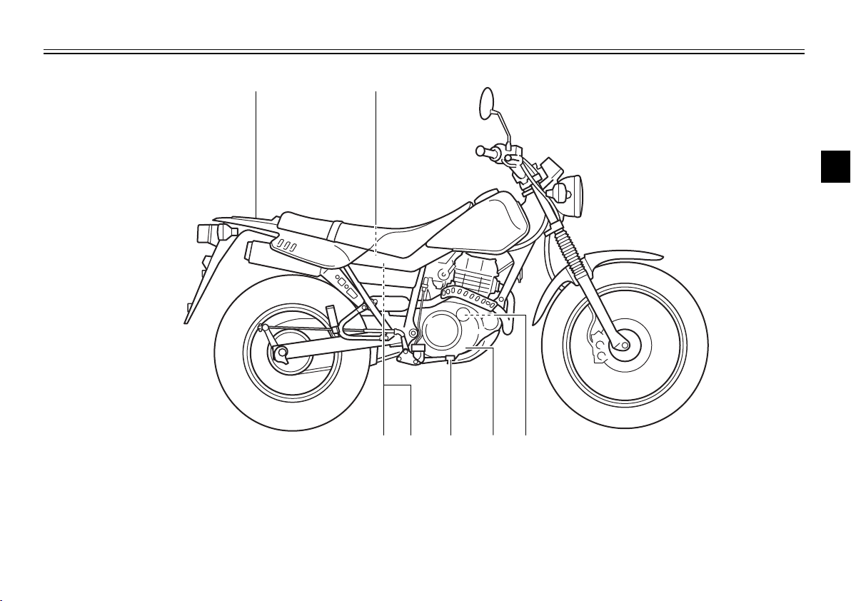
DESCRIPTION ................................................. 2-1
Left view ......................................................... 2-1
Right view ...................................................... 2-2
Controls and instruments ............................... 2-3
INSTRUMENT AND CONTROL FUNCTIONS . 3-1
Main switch .................................................... 3-1
Indicator lights ................................................ 3-1
Speedometer unit .......................................... 3-2
Handlebar switches ........................................ 3-2
Clutch lever .................................................... 3-4
Shift pedal ...................................................... 3-4
Brake lever ..................................................... 3-4
Brake pedal .................................................... 3-5
Fuel tank cap ................................................. 3-5
Fuel ................................................................ 3-6
Fuel cock ........................................................ 3-7
Starter (choke) knob ...................................... 3-8
Steering lock .................................................. 3-8
Seat ................................................................ 3-9
Helmet holder ................................................. 3-9
Shock absorber ............................................ 3-10
Carrier .......................................................... 3-10
Luggage strap holders ................................. 3-10
Sidestand ..................................................... 3-11
Ignition circuit cut-off system ........................ 3-11
PRE-OPERATION CHECKS ............................ 4-1
Pre-operation check list ................................. 4-1
OPERATION AND IMPORTANT RIDING
POINTS ............................................................. 5-1
Starting the engine ......................................... 5-1
Starting a warm engine .................................. 5-2
Shifting ........................................................... 5-3
Recommended shift points
(for Switzerland only) .................................. 5-3
Tips for reducing fuel consumption ................ 5-4
Engine break-in .............................................. 5-4
Parking ........................................................... 5-5
PERIODIC MAINTENANCE AND MINOR
REPAIR ............................................................. 6-1
Owner’s tool kit .............................................. 6-1
Periodic maintenance and lubrication chart ... 6-2
Removing and installing panels ..................... 6-5
Checking the spark plug ................................ 6-7
Engine oil and oil filter element ...................... 6-9
Cleaning the air filter element and check
hose .......................................................... 6-12
Adjusting the carburetor ............................... 6-14
Adjusting the engine idling speed ................ 6-14
1
2
3
4
5
6
5RS-9-E0 (TW125) 7/30/01 6:02 PM Page 5

Adjusting the throttle cable free play ............ 6-15
Adjusting the valve clearance ...................... 6-16
Tires ............................................................. 6-16
Spoke wheels ............................................... 6-18
Adjusting the clutch lever free play .............. 6-19
Adjusting the brake lever free play ............... 6-20
Adjusting the brake pedal position and
free play .................................................... 6-21
Adjusting the rear brake light switch ............ 6-22
Checking the front brake pads and
rear brake shoes ....................................... 6-23
Checking the brake fluid level ...................... 6-24
Changing the brake fluid .............................. 6-25
Drive chain slack .......................................... 6-25
Lubricating the drive chain ........................... 6-27
Checking and lubricating the cables ............ 6-27
Checking and lubricating the throttle grip
and cable .................................................. 6-28
Checking and lubricating the brake and
shift pedals ................................................ 6-28
Checking and lubricating the brake and
clutch levers .............................................. 6-29
Checking and lubricating the sidestand ....... 6-29
Lubricating the rear suspension ................... 6-30
Checking the front fork ................................. 6-30
Checking the steering .................................. 6-31
Checking the wheel bearings ....................... 6-31
Battery .......................................................... 6-32
Replacing the fuse ....................................... 6-33
Replacing the headlight bulb ........................ 6-34
Replacing a turn signal light bulb ................. 6-36
Replacing the tail/brake light bulb ................ 6-36
Supporting the motorcycle ........................... 6-37
Front wheel .................................................. 6-38
Rear wheel ................................................... 6-40
Troubleshooting ........................................... 6-42
Troubleshooting chart .................................. 6-43
MOTORCYCLE CARE AND STORAGE .......... 7-1
Care ............................................................... 7-1
Storage .......................................................... 7-4
SPECIFICATIONS ............................................ 8-1
Conversion table ............................................ 8-5
CONSUMER INFORMATION ........................... 9-1
Identification numbers .................................... 9-1
Key identification number ............................... 9-1
Vehicle identification number ......................... 9-1
Model label ..................................................... 9-2
TABLE OF CONTENTS
7
8
9
5RS-9-E0 (TW125) 7/30/01 6:02 PM Page 6

1-1
EAU00021 QGIVE SAFETY THE RIGHT OF WAY
1
Motorcycles are fascinating vehicles, which can give you an unsurpassed feeling of power and free-
dom. However, they also impose certain limits, which you must accept; even the best motorcycle
does not ignore the laws of physics.
Regular care and maintenance are essential for preserving value and operating condition of your
motorcycle. Moreover, what is true for the motorcycle is also true for the rider: good performance
depends on being in good shape. Riding under the influence of medication, drugs and alcohol is, of
course, out of the question. Motorcycle riders—more than car drivers—must always be at their mental
and physical best. Under the influence of even small amounts of alcohol, there is a tendency to take
dangerous risks.
Protective clothing is as essential for the motorcycle rider as seat belts are for car drivers and passen-
gers. Always wear a complete motorcycle suit (whether made of leather or tear-resistant synthetic
materials with protectors), sturdy boots, motorcycle gloves and a properly fitting helmet. Optimum pro-
tective wear, however, should not encourage carelessness. Although full-coverage helmets and suits,
in particular, create an illusion of total safety and protection, motorcyclists will always be vulnerable.
Riders who lack critical self-control run the risk of going too fast and are apt to take chances. This is
even more dangerous in wet weather. The good motorcyclist rides safely, predictably and defensive-
ly—avoiding all dangers, including those caused by others.
Enjoy your ride!
5RS-9-E0 (TW125) 7/30/01 6:02 PM Page 7

2-1
EAU00026
DESCRIPTION
2
Left view
1. Headlight (page 6-34)
2. Steering lock (page 3-8)
3. Fuel tank (page 3-5)
4. Fuel cock (page 3-7)
5. Helmet holder (page 3-9)
6. Luggage strap holders (page 3-10)
7. Drive chain adjusting plates (page 6-26)
8. Air filter element (page 6-12)
9. Shift pedal (page 3-4)
3456
7
8
9
1 2
5RS-9-E0 (TW125) 7/30/01 6:02 PM Page 8

2-2
DESCRIPTION
2
Right view
10. Carrier (page 3-10)
11. Battery (page 6-32)
12. Engine oil filter element (page 6-9)
13. Engine oil level check window (page 6-9)
14. Brake pedal (page 3-5, 6-21)
15. Owner’s tool kit (page 6-1)
16. Fuse (page 6-33)
10 11
15 14 12
13
16
5RS-9-E0 (TW125) 7/30/01 6:02 PM Page 9

2-3
DESCRIPTION
2
Controls and instruments
1. Clutch lever (page 3-4, 6-19)
2. Left handlebar switches (page 3-2)
3. Speedometer unit (page 3-2)
4. Starter (choke) knob (page 3-8)
5. Main switch (page 3-1)
6. Indicator lights (page 3-1)
7. Right handlebar switches (page 3-3)
8. Brake lever (page 3-4, 6-20)
9. Throttle grip (page 6-15, 6-28)
10. Fuel tank cap (page 3-5)
123
45678
9
10
5RS-9-E0 (TW125) 7/30/01 6:02 PM Page 10

3-1
EAU00027 INSTRUMENT AND CONTROL FUNCTIONS
3
EAU00028
Main switch
Main switch
The main switch controls the ignition
and lighting systems. The various
main switch positions are described
below.
EAU00036
ON
All electrical systems are supplied
with power, and the engine can be
started. The key cannot be removed.
EAU00038
OFF
All electrical systems are off. The key
can be removed.
EAU00061
Neutral indicator light “N”
This indicator light comes on when
the transmission is in the neutral
position.
OFF ON
EAU00056
Indicator lights
EAU00057
Turn signal indicator light “5”
This indicator light flashes when the
turn signal switch is pushed to the left
or right.
EAU00063
High beam indicator light “&”
This indicator light comes on when
the high beam of the headlight is
switched on.
312
1. Turn signal indicator light “5”
2. High beam indicator light “&”
3. Neutral indicator light “N”
5RS-9-E0 (TW125) 7/30/01 6:02 PM Page 11

3-2
EAU01087
Speedometer unit
The speedometer unit is equipped
with a speedometer, an odometer
and a tripmeter. The speedometer
shows riding speed. The odometer
shows the total distance traveled.
The tripmeter shows the distance
traveled since it was last set to zero
with the reset knob. The tripmeter
can be used to estimate the distance
that can be traveled with a full tank of
fuel. This information will enable you
to plan future fuel stops.
NOTE:
Only for the German model equipped
with a speed limiter:
The speed limiter prevents the motor-
cycle from exceeding a riding speed
of 80 km/h.
INSTRUMENT AND CONTROL FUNCTIONS
3
4
12
3
1. Speedometer
2. Odometer
3. Tripmeter
4. Reset knob
EAU00118
Handlebar switches
EAU03898
Light switch “9/'/:”
Set this switch to “'” to turn on
the auxiliary light, meter lighting and
taillight. Set the switch to “:” to turn
on the headlight also. Set the switch
to “9” to turn off all the lights.
4
1
2
3
1. Light switch “9/'/:”
2. Dimmer switch “&/%”
3. Turn signal switch “4/6”
4. Horn switch “*”
5RS-9-E0 (TW125) 7/30/01 6:03 PM Page 12

3-3
INSTRUMENT AND CONTROL FUNCTIONS
3
EAU03888
Dimmer switch “&/%”
Set this switch to “&” for the high
beam and to “%” for the low beam.
EAU03889
Turn signal switch “4/6”
To signal a right-hand turn, push this
switch to “6”. To signal a left-hand
turn, push this switch to “4”. When
released, the switch returns to the
center position. To cancel the turn
signal lights, push the switch in after
it has returned to the center position.
EAU00129
Horn switch “*”
Press this switch to sound the horn.
EAU00143
Start switch “,”
Push this switch to crank the engine
with the starter.
EC000005
cC
See page 5-1 for starting instruc-
tions prior to starting the engine.
EAU03890
Engine stop switch “#/$”
Set this switch to “#” before starting
the engine. Set this switch to “$” to
stop the engine in case of an emer-
gency, such as when the motorcycle
overturns or when the throttle cable is
stuck.
1
2
1. Engine stop switch “#/$”
2. Start switch “,”
5RS-9-E0 (TW125) 7/30/01 6:03 PM Page 13

3-4
EAU00152
Clutch lever
The clutch lever is located at the left
handlebar grip. To disengage the
clutch, pull the lever toward the han-
dlebar grip. To engage the clutch,
release the lever. The lever should
be pulled rapidly and released slowly
for smooth clutch operation.
The clutch lever is equipped with a
clutch switch, which is part of the igni-
tion circuit cut-off system. (See page
3-11 for an explanation of the ignition
circuit cut-off system.)
INSTRUMENT AND CONTROL FUNCTIONS
3
1
1. Clutch lever
EAU00158
Brake lever
The brake lever is located at the right
handlebar grip. To apply the front
brake, pull the lever toward the han-
dlebar grip.
1
1. Brake lever
EAU00157
Shift pedal
The shift pedal is located on the left
side of the engine and is used in
combination with the clutch lever
when shifting the gears of the
5-speed constant-mesh transmission
equipped on this motorcycle.
1
1. Shift pedal
5RS-9-E0 (TW125) 7/30/01 6:03 PM Page 14

3-5
INSTRUMENT AND CONTROL FUNCTIONS
3
EAU00162
Brake pedal
The brake pedal is on the right side
of the motorcycle. To apply the rear
brake, press down on the brake
pedal.
1
1. Brake pedal
To install the fuel tank cap
1. Insert the fuel tank cap into the
tank opening with the key insert-
ed in the lock, and then turn the
cap 1/3 turn clockwise.
2. Turn the key 1/4 turn clockwise,
and then remove it.
NOTE:
The fuel tank cap cannot be installed
unless the key is in the lock. In addi-
tion, the key cannot be removed if the
cap is not properly installed and
locked.
EW000023
w
Make sure that the fuel tank cap is
properly closed and locked before
riding.
EAU00177
Fuel tank cap
To remove the fuel tank cap
1. Insert the key into the lock and
turn it 1/4 turn counterclockwise.
2. Turn the fuel tank cap 1/3 turn
counterclockwise and pull it off.
1
b
a
1. Fuel tank cap
a. Unlock.
b. Open.
5RS-9-E0 (TW125) 7/30/01 6:03 PM Page 15

3-6
INSTRUMENT AND CONTROL FUNCTIONS
3
EAU03753
Fuel
Make sure that there is sufficient fuel
in the tank. Fill the fuel tank to the
bottom of the filler tube as shown.
EW000130
w
8Do not overfill the fuel tank,
otherwise it may overflow
when the fuel warms up and
expands.
8Avoid spilling fuel on the hot
engine.
1
2
1. Filler tube
2. Fuel level
ECA00104
cC
Use only unleaded gasoline. The
use of leaded gasoline will cause
severe damage to internal engine
parts, such as the valves and pis-
ton rings, as well as to the exhaust
system.
Your Yamaha engine has been
designed to use regular unleaded
gasoline with a research octane num-
ber of 91 or higher. If knocking (or
pinging) occurs, use a gasoline of a
different brand or premium unleaded
fuel. Use of unleaded fuel will extend
spark plug life and reduce mainte-
nance costs.
EAU00185
cC
Immediately wipe off spilled fuel
with a clean, dry, soft cloth, since
fuel may deteriorate painted sur-
faces or plastic parts.
EAU04284
Recommended fuel:
REGULAR UNLEADED
GASOLINE ONLY
Fuel tank capacity:
Total amount:
7.0 L
Reserve amount:
1.0 L
5RS-9-E0 (TW125) 7/30/01 6:03 PM Page 16

3-7
INSTRUMENT AND CONTROL FUNCTIONS
3
EAU03050
Fuel cock
The fuel cock supplies fuel from the
tank to the carburetor while filtering it
also.
The fuel cock has three positions:
OFF
With the lever in this position, fuel will
not flow. Always return the lever to
this position when the engine is not
running.
RES
ON
FUEL
OFF
1
1. Arrow mark positioned over “OFF”
RES
This indicates reserve. If you run out
of fuel while riding, move the lever to
this position. Fill the tank at the first
opportunity. Be sure to set the lever
back to “ON”after refueling!
OFF
ON
FUEL
RES
1
RES
1. Arrow mark positioned over “RES”
ON
With the lever in this position, fuel
flows to the carburetor. Normal riding
is done with the lever in this position.
ON FUEL
RES
OFF
1
ON
1. Arrow mark positioned over “ON”
OFF: Closed position ON: Normal position RES: Reserve position
5RS-9-E0 (TW125) 7/30/01 6:03 PM Page 17

3-8
INSTRUMENT AND CONTROL FUNCTIONS
3
EAU04038
Starter (choke) knob “1”
Starting a cold engine requires a rich-
er air-fuel mixture, which is supplied
by the starter (choke).
Move the knob in direction ato turn
on the starter (choke).
Move the knob in direction bto turn
off the starter (choke).
a
b
1
1. Starter (choke) knob “1”
4. Check that the steering is locked,
remove the key, and then close
the lock cover.
To unlock the steering
1. Open the steering lock cover,
and then insert the steering lock
key.
2. Push the key in, turn it 1/8 turn
counterclockwise so that it
moves out, and then release it.
3. Remove the key, and then close
the lock cover.
EAU03342
Steering lock
Steering lock
To lock the steering
1. Turn the handlebar all the way to
right.
2. Open the steering lock cover,
and then insert the steering lock
key.
3. Turn the key 1/8 turn counter-
clockwise, push it in while turning
the handlebar slightly to the left,
and then turn the key 1/8 turn
clockwise.
2
1
1. Steering lock cover
2. Steering lock
5RS-9-E0 (TW125) 7/30/01 6:03 PM Page 18

3-9
INSTRUMENT AND CONTROL FUNCTIONS
3
EAU01092
Seat
To remove the seat
Remove the bolts, and then pull the
seat off.
1
1. Bolt (×2)
EAU00260
Helmet holder
To open the helmet holder, insert the
key into the lock, and then turn the
key as shown.
To lock the helmet holder, place it in
the original position, and then remove
the key.
EW000030
w
Never ride with a helmet attached
to the helmet holder, since the hel-
met may hit objects, causing loss
of control and possibly an acci-
dent.
1
1. Helmet holder
To install the seat
1. Insert the projection on the front
of the seat into the seat holder
as shown.
2. Place the seat in the original
position, and then tighten the
bolts.
NOTE:
Make sure that the seat is properly
secured before riding.
1
2
1. Projection
2. Seat holder
5RS-9-E0 (TW125) 7/30/01 6:03 PM Page 19
Other manuals for TW125
4
Table of contents
Other Yamaha Motorcycle manuals

Yamaha
Yamaha TT-R110EF User manual

Yamaha
Yamaha WR450F 2022 User manual

Yamaha
Yamaha FZ8-NA User manual

Yamaha
Yamaha XZ550 1982 User manual

Yamaha
Yamaha FJ Instruction manual

Yamaha
Yamaha TDM900 User manual

Yamaha
Yamaha YZFR6Y User manual

Yamaha
Yamaha TW200 User manual

Yamaha
Yamaha XS650SE Install guide

Yamaha
Yamaha 2011 XVS1300AA User manual

Yamaha
Yamaha Fazer FZ6-SHG User manual

Yamaha
Yamaha VMX12 93 Manual

Yamaha
Yamaha Venture XVZ13TFX User manual

Yamaha
Yamaha R6 YZF600 User manual

Yamaha
Yamaha TW200E User manual

Yamaha
Yamaha TX650 User manual

Yamaha
Yamaha DT125RE 2005 User manual

Yamaha
Yamaha XV250M1 2020 User manual

Yamaha
Yamaha YZ85(D) User manual

Yamaha
Yamaha YZF User manual