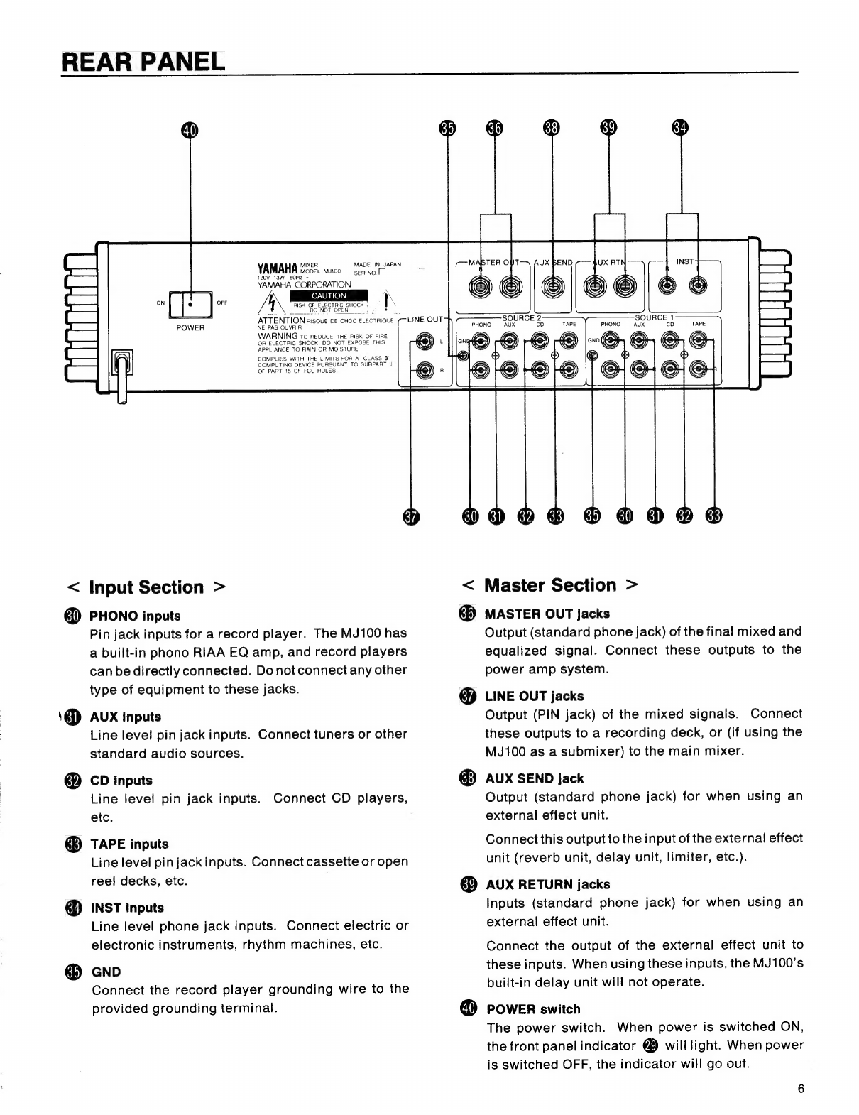
Yamaha MJ100 User manual

YAMAHA
MIXER
NATO
OS
OPERATING
MANUAL
YAMAHA
MIXER
Feck
ICC?
d
1
RETURN
H
o
APT
SID:
LONG,
CH
(O
DELAY
TIME
o
10
o
10
REGENERATION
SOURCE
1
LINE
OUT
MASTER
CROSS
FADER

Thank
you
for
purchasing
the
Yamaha
MJ100
Mixer.
In
order
to
take
full
advantage
of
the
MJ100’s
capabilities
and
to
enjoy
long,
trouble-free
op-
eration,
please
read
this
manual
before
use,
and
keep
it
in
a
safe
place
with
the
warranty
for
later
reference.
CAUTION
RISK
OF
ELECTRIC
SHOCK
DO
NOT
OPEN
CAUTION:
TO
REDUCE
THE
RISK
OF
ELECTRIC
SHOCK,
DO
NOT
REMOVE
COVER
(OR
BACK)
NO
USER-SERVICEABLE
PARTS
INSIDE,
REFER
SERVICING
TO
QUALIFIED
SERVICE
PERSONNEL.
FEATURES
O
Five-band
+/—
12dB
Graphic
Equalizer
allows
you
to
adjust
the
sound
to
suit
any
location
or
speaker
system.
Built-in
RIAA
phono
equalizer
for
directly
con-
necting
record
players.
Phantom
power
for
4P-type
condensor
micro-
phone.
Built-in
three
mode
delay
(short,
mid,
long)
for
creative
sounds.
Monitor
select
switches
allow
you
to
check
input
or
output
through
a
set
of
headphones.
@
Explanation
of
Graphical
Symbols
The
lightning
flash
with
arrowhead
symbol,
within
an
equilateral
triangle,
is
intended
to
alert
you
to
the
presence
of
uninsulated
"dangerous
voltage”
within
the
product's
enclosure
that
may
be
of
sufficient
magnitude
to
constitute
a
risk
of
electric
shock
to
persons.
The
exclamation
point
within
an
equilateral
triangle
is
intended
to
alert
you
to
the
presence
of
important
operating
and
maintenance
(servicing)
instructions
in
the
literature
accompanying
the
appliance.
CONTENTS

PRECAUTIONS
@
Location
Using
the
product
in
the
following
types
of
location
may
cause
malfunction
and
damage
the
product.
e
In
direct
sunlight
or
near
a
heater
@
In
extremely
cold
locations
&
In
excessive
dust
or
humidity
@
Where
the
unit
will
be
subjected
to
excessive
vibration
Handling
Strong
physical
shocks
to
the
unit
can
cause
damage.
Handle
it
with
care.
Do
not
apply
ex-
cessive
force
to
the
switches
or
controls.
Power
Cable
To
prevent
shorting
or
damaging
the
power
cable,
grasp
the
connector—not
the
cable—when
unplug-
ging
it.
When
you
will
not
be
using
the
unit
for
an
extended
period
of
time,
unplug
the
power
cable
from
the
AC
power
source.
Power
Source
Make
sure
that
the
power
source
voltage
specified
on
the
rear
panel
matches
your
local
AC
power
supply.
Moving
the
Unit
To
prevent
short
circuits
or
cable
damage,
unplug
all
cables
before
moving
the
unit.
Connections
Before
connecting
the
MJ100
with
other
units,
turn
the
power
of
all
units
OFF
and
turn
the
MJ100
master
volume
all
the
way
down.
Do
Not
Open
the
Unit
This
product
contains
no
user-servicable
parts.
Refer
all
maintenance
to
qualified
YAMAHA
ser-
vice
personnel.
Opening
the
unit
and/or
tampering
with
the
internal
circuitry
will
void
the
warranty.
Cleaning
Never
use
solvents
such
as
benzine
or
thinner
to
clean
the
unit,
and
do
not
use
aerosol-type
sprays
nearby.
Wipe
the
unit
clean
with
a
soft,
dry
cloth.
Electrical
Storms
In
the
event
of
an
electrical
storm
(lightning)
nearby,
unplug
the
power
cable
from
the
AC
power
source.
Warranty
When
purchasing
the
unit,
be
sure
to
fill
out
the
warranty,
and
have
it
stamped
by
the
dealer.
If
you
fail
to
do
so,
you
may
be
charged
for
repair
service
performed
even
within
the
warranty
period.
SAFETY
INSTRUCTIONS
(PREPARED
IN
ACCORDANCE
WITH
UL
STANDARD
1270)
=
N
>
o
a
N
E
©
Read
Instructions
—
Ali
the
safety
and
operating
instructions
should
be
read
before
the
appliance
is
operated.
Retain
Instructions
—
The
safety
and
operating
instructions
should
be
retained
for
future
reference.
Heed
Warnings
—
All
warnings
on
the
appliance
and
in
the
op-
erating
instructions
should
be
adhered
to.
Follow
Instructions
—
All
operating
and
use
instructions
should
be
followed.
Water
and
Moisture
—
The
appliance
should
not
be
used
near
water
—
for
example,
near
a
bathtub,
washbowl,
kitchen
sink,
laundry
tub,
in
a
wet
basement,
or
near
a
swimming
pool,
and
the
like.
Carts
and
Stands
—
The
appliance
should
be
used
only
with
a
cart
or
stand
that
is
recommended
by
the
manufacturer.
Wall
or
Ceiling
Mounting
—
The
appliance
should
be
mounted
to
a
wail
or
ceiling
only
as
recommended
by
the
manufacturer.
Ventilation
—
The
appliance
should
be
situated
so
that
its
to-
cation
or
position
does
not
interfere
with
its
proper
ventilation.
For
example,
the
appliance
should
not
be
situated
on
a
bed,
sofa,
rug,
or
similar
surface
that
may
block
the
ventilation
openings;
or
placed
in
a
built-in
installation,
such
as
a
bookcase
or
cabinet
that
may
impede
the
flow
of
air
through
the
ventilation
openings.
Heat—
The
appliance
should
be
situated
away
from
heat
sources
such
as
radiators,
heat
registers,
stoves,
or
other
appliances
(including
amplifiers)
that
produce
heat.
Power
Sources
—
The
appliance
should
be
connected
to
a
power
supply
only
of
the
type
described
in
the
operating
instructions
or
as
marked
on
the
appliance.
11.
Power-Cord
Protection
—
Power-supply
cords
should
be
routed
so
that
they
are
not
likely
to
be
walked
on
or
pinched
by
items
placed
upon
or
againstthem,
paying
particular
attention
to
cords
at
plugs,
convenience
receptacles,
and
the
point
where
they
exit
from
the
appliance.
Cleaning
—
The
appliance
should
be
cleaned
only
as
recom-
mended
by
the
manufacturer.
Nonuse
Periods
—
The
power
cord
of
the
appliance
should
be
unplugged
from
the
outlet
when
left
unused
for
a
long
period
of
time.
Object
and
Liquid
Entry
—
Care
should
be
taken
so
that
objecis
do
not
fall
and
liguids
are
not
spilled
into
the
enclosure
through
openings.
Damage
Reguiring
Service
—
The
appliance
should
be
serviced
by
gualified
service
personnel
when:
A.
The
power-supply
cord
or
the
plug
has
been
damaged;
or
B.
Objects
have
fallen,
or
liquid
has
been
spilled
into
the
appliance;
or
C.
The
appliance
has
been
exposed
to
rain;
or
D.
The
appliance
does
not
appear
to
operate
normally
or
exhibits
a
marked
change
in
performance;
or
E.
The
appliance
has
been
dropped,
or
the
enclosure
dam-
aged.
Servicing
—
The
user
should
notattemptto
service
the
appliance
beyond
that
described
in
the
operating
instructions.
All
other
servicing
should
be
referred
to
gualified
service
personnel.

CONTROL
PANEL
|
DOHOD
o
OO
gh ga gi cb
YAMAHA
`
H
5
o
(
O
0
H
10
AUX
°
SEND
|
eum
—
KE
+
Sa
gue
ago
TOLL
|
TO
|
Ka
és
RODO
va
fd
`
o
>
atc,
x
E
d
R
Lem
Z
ma
=
,
E
|
|
|
ze
:
mD
E
N
SHORT
MID
LONG
Le
190
400
de
aK
Ke
L
R
DELAY
TIME
D
10
0
10
GRAPHIC
EQUALIZER
PAN
REGENERATION
PHONES
I
|
ud
vo
ee
A
a
epunce
C
H
°
=
S
Y
IH
K
SOURCE
Cl
6
DT
ve
[ES
=
=
s
s
L
11
7
S|
S
pesch
Es
SO
TE
ES
E
ES
E
ds
12
ee
5s
—
5 5
==
ic
Pe
ES
-
=
|
=
]
e
3—
3
3
En
—
GE
—
}
INST
I)
jo
Ave
CA
7
;
K
(m
1
1
1 1
SOURCE:
==
SOURCE
2
MIC
INST
LINEJOUT
MASTER
MONITOR
a
SELECT
L
Se
—
Ul
|
pe
ra
re:
MIC
PHONES
CROSS|FADER
E
+
Leg
cn
co
>
CO
N
NO
NO
Oo
RO
OO
AS
D
<
Input
Section
>
O
mic
jack
G
PAN
control
(mic
pan)
Special
mic
input
for
use
with
a
goose
neck
con-
The
PAN
control
adjusts
the
mic
signal
in
the
stereo
densor
mic
MJM-10
(option).
field
of
the
LINE
OUT
signal.
Rotate
PAN
to
the
ieft
o
MIC
jack
(or
right)
to
place
the
signal
toward
the
left
(or
right)
ZE
â
of
the
stereo
field.
In
the
center
position,
the
mic
Normal
mic
input
for
use
with
standard
phone
plug
,
,
type
sound
will
be
in
the
center
of
the
stereo
field.
O
AUX
control
(mic
effect)
The
AUX
control
adjusts
the
signal
sent
from
the
mic
to
the
internal
delay
circuit
or
the
rear
panel
AUX
SEND.
When
an
effects
device
is
connected
Note)
When
both
mic
inputs
1
and
2
are
used,
input
2
has
priority.
(The
mic
connected
to
input
1
will
not
be
used.)
O
Mic
fader
between
AUX
SEND
and
AUX
RETURN,
the
front
This
adjusts
the
level
of
the
mic
connected
to
input
panel
AUX
will
regulate
the
depth
of
the
effect.
The
1
or
2.
Use
this
control
to
balance
the
mic
with
the
level
increases
as
you
rotate
AUX
to
the
right.
other
input
channels.
@
ON/OFF
switch
This
switches
the
mic
on/off,
allowing
you
to
turn
the
mic
off
without
changing
the
fader
level.

@
INST
fader
The
INST
fader
adjusts
the
level
of
electronic
or
electric
instruments
connected
to
the
rear
panel
<
Master
Section
>
@
5-BAND
GRAPHIC
EQUALIZER
INST
L,
R
inputs.
Both
L
and
R
inputs
will
be
con-
trolled
together.
Use
this
control
to
balance
the
INST
input
with
the
other
input
channels.
G
ON/OFF
switch
This
switches
the
INST
inputs
on/off,
allowing
you
to
turn
off
the
input
without
changing
the
fader
level.
Both
L
and
R
inputs
will
be
turned
on/off
together.
©
AUX
control
(inst
effect)
The
AUX
control
adjusts
the
signal
sent
from
the
INST
inputs
to
the
internal
delay
circuit
or
the
rear
panel
AUX
SEND.
The
L
and
R
signals
will
be
mixed.
You
cannot
send
only
L
or
only
R.
When
an
effects
device
is
connected
between
AUX
SEND
and
AUX
RETURN,
the
front
panel
AUX
control
will
regulate
the
depth
of
the
effect.
The
level
will
increase
as
you
rotate
AUX
to
the
right.
d
d
dëi
dë
INPUT
SELECT
switches
These
switches
select
the
sources
connected
to
the
rear
panel
SOURCE
1
and
SOURCE
2
inputs.
Press
the
switch
to
select
the
corresponding
source.
D
dë
SOURCE
1,
2
faders
These
adjust
the
level
of
the
input
sources
selected
by
the
Input
Select
switches.
A
single
fader
controls
both
L
and
R.
Use
these
faders
to
balance
the
SOURCE
1
and
2
inputs
with
the
other
input
chan-
nels.
@
CROSS
FADER
This
fader
adjusts
the
balance
between
SOURCE
1
and
SOURCE
2,
as
follows.
e
As
the
CROSS
FADER
is
moved
to
the
left,
SOURCE
1
becomes
louder
and
SOURCE
2
be-
comes
softer.
@
When
the
CROSS
FADER
is
in
the
center
posi-
tion,
SOURCE
1
and
2
are
the
same
level.
e
As
the
CROSS
FADER
is
moved
to
the
right,
SOURCE
1
becomes
softer
and
SOURCE
2
be-
comes
louder.
This
is
a
graphic
equalizer
with
center
frequencies
at
100Hz,
400Hz,
1kHz,
3kHz
and
8kHz,
with
+/—12dB
of
control
over
each
band.
Moving
a
slider
in
the
plus
(+)
direction
will
emphasize
that
frequency
range.
Moving
a
slider
in
the
minus
(—)
direction
will
de-emphasize
that
frequency
range.
When
the
slider
is
at
0,
the
response
is
flat.
Adjust
equalizer
settings
to
suit
the
room
or
speaker
system
you
are
using.
The
equalized
signal
is
sent
only
from
the
MASTER
OUT
L,
R
jacks.
Each
slider
of
the
equalizer
affects
both
channels
L
and
R
in
the
same
way.
@
MASTER
fader
The
MASTER
fader
regulates
the
level
output
from
the
rear
panel
MASTER
OUT
L,
R
jacks.
It
controls
the
final
volume
(channels
L
and
R
together)
of
the
mixed
input
sources.
Adjust
the
MASTER
fader
level
according
to
the
VU
meters
(4D,
D).
®
;
(20)
Output
VU
meters
These
meters
indicate
the
level
of
the
signal
output
from
the
rear
panel
MASTER
OUT
L
and
R
jacks.
The
levels
will
depend
on
the
MASTER
fader
set-
ting.
Adjust
the
MASTER
fader
@
so
that
the
loudest
signal
makes
the
meters
indicate
0dB.
A)
LINE
OUT
fader
The
LINE
OUT
fader
regulates
the
level
output
from
the
rear
panel
LINE
OUT
L,
R
jacks.
It
controls
the
final
volume
(channels
L
and
R
together)
of
the
mixed
input
sources
sent
from
the
LINE
OUT
jacks.
6)
DELAY
TIME
select
switch
The
MJ100
has
a
built-in
delay
unit.
When
the
rear
.
panel
AUX
RETURN
jacks
are
not
being
used,
a
Long,
Mid
or
Short
delay
can
be
selected.
@
REGENERATION
control
When
the
rear
panel
AUX
RETURN
jacks
are
not
being
used,
the
REGENERATION
control
regulates
the
amount
of
signal
sent
to
the
built-in
delay
unit.
Use
REGENERATION
together
with
@
RETURN
to
adjust
the
amount
of
delay
effect.
When
the
RETURN
control
is
at
0,
there
will
beno
delay
effect.
The
built-in
delay
unit
can
be
used
only
by
the
MIC
and
INST
inputs.
Note)
fan
effects
device
is
connected
to
the
rear
panel
AUX
RETURN
inputs,
the
built-in
delay
unit
will
not
operate,
and
@
and
®
will
have
no
effect.

(24)
SEND
control
The
SEND
control
regulates
the
level
of
the
signal
output
from
the
rear
panel
AUX
SEND
jack.
When
using
an
external
effects
unit,
this
control
regulates
the
level
of
the
signal
sent
to
the
external
effects
unit.
Only
the
MIC
and
INST
inputs
can
send
a
signal
through
the
SEND
control
to
the
rear
panel
AUX
SEND
jack.
(2)
RETURN
control
The
RETURN
control
regulates
the
level
of
the
signal
received
from
the
rear
panel
AUX
RETURN
inputs.
When
an
external
effects
device
is
con-
nected,
this
control
regulates
the
level
of
the
signal
received
from
the
external
effects
unit.
If
nothing
is
connected
to
the
AUX
RETURN
jacks,
this
control
regulates
the
level
of
the
signal
from
the
built-in
delay
unit.
@
MONITOR
SELECT
switches
These
switches
select
the
signal
to
be
monitored
in
the
headphones.
The
monitor
signal
is
selected
as
follows.
e
SOURCE
1
&
2...
The
Selected
Source
1
mixed
(L
FR)
signal
input
the
left
channel,
and
Selected
Source
2
mixed
(L+R)
signal
input
to
the
right
channel.
All
signals
are
before
the
source
fader.
e
MIC
...
The
MIC
signal
input
after
the
mic
amp
but
before
the
MIC
fader.
l
O
INST
...
The
INST
signal
input
before
the
INST
fader.
e
MASTER
OUT
...
The
mixed
signal
output
from
the
MASTER
OUT
jacks.
Input
signals
are
mon-
itored
before
the
faders,
and
output
signals
are
monitored
after
the
faders.
@
PHONES
LEVEL
control
The
MONITOR
LEVEL
control
regulates
the
level
of
the
headphone
monitor
signal.
The
headphone
will
monitor
the
signal
selected
by
the
MONITOR
SELECT
switches.
Q)
PHONES
jack
Connect
a
pair
of
stereo
headphones
to
this
jack
to
monitor
the
signal
selected
by
(26)
and
regulated
by
@.
@)
POWER
indicator
When
the
rear
panel
power
switch
is
turned
on,
this
indicator
will
light.

REAR
PANEL
<
40
39
MADE
IN
JAPAN
SER
No
YAMAHA
nose.
muco
120V
13W
60Hz
YAMAHA
CORPORATION
A
|
Kee
RISK
OF
ELECTRIC
SHOCK
:
\
+
[OO
DONOY
OPEN)
8,
ATTENTION
risque
DE
CHOC
ELECTRIQUE
NE
PAS
OUVRIR
WARNING
To
REDUCE
THE
RISK
OF
FIRE
OR
ELECTRIC
SHOCK,
DO
NOT
EXPOSE
THIS
APPLIANCE
TO
RAIN
OR
MOISTURE
COMPLIES
WITH
THE
LIMITS
FOR
A
CLASS
B
COMPUTING
DEVICE
PURSUANT
TO
SUBPART
J
OF
PART
15
OF
FCC
RULES.
37
Input
Section
>
gd
PHONO
inputs
&
o
Pin
jack
inputs
for
a
record
player.
The
MJ100
has
a
built-in
phono
RIAA
EO
amp,
and
record
players
can
be
directly
connected.
Do
not
connect
any
other
type
of
eguipment
to
these
jacks.
AUX
inputs
Line
level
pin
jack
inputs.
Connect
tuners
or
other
standard
audio
sources.
CD
inputs
Line
level
pin
jack
inputs.
etc.
Connect
CD
players,
TAPE
inputs
Line
level
pin
jackinputs.
Connect
cassette
or
open
reel
decks,
etc.
INST
inputs
Line
level
phone
jack
inputs.
Connect
electric
or
electronic
instruments,
rhythm
machines,
etc.
GND
Connect
the
record
player
grounding
wire
to
the
provided
grounding
terminal.
30
38
39
34
r—
MASTER
OUT
[
J
UX
RT
INST
WE
|
CH
ee|e
2
TAPE
PHONO
SOURCE
T
d
E
E
Lë
0,0,0
-00e
—r
a
D
iz
eeleeeieieiel
|=
EI0
6D
6D
6
OD
<
D
@
Master
Section
>
MASTER
OUT
jacks
Output
(standard
phone
jack)
of
the
final
mixed
and
equalized
signal.
Connect
these
outputs
to
the
power
amp
system.
LINE
OUT
jacks
Output
(PIN
jack)
of
the
mixed
signals.
Connect
these
outputs
to
a
recording
deck,
or
(if
using
the
MJ100
as
a
submixer)
to
the
main
mixer.
AUX
SEND
jack
Output
(standard
phone
jack)
for
when
using
an
external
effect
unit.
Connect
this
output
to
the
input
of
the
external
effect
unit
(reverb
unit,
delay
unit,
limiter,
etc.).
AUX
RETURN
jacks
Inputs
(standard
phone
jack)
for
when
using
an
external
effect
unit.
Connect
the
output
of
the
external
effect
unit
to
these
inputs.
When
using
these
inputs,
the
MJ100's
built-in
delay
unit
will
not
operate.
POWER
switch
The
power
switch.
When
power
is
switched
ON,
the
front
panel
indicator
@
will
light.
When
power
is
switched
OFF,
the
indicator
will
go
out.

SETUP
EXAMPLE
@
Basic
setup
L
Main
speakers
>L
LOQ]
O
CENT]
Tape
deck
Keyboard
Sé
o
e
co
&
=
aw
"astros
RPV
Gp cm
CED
ca
YAMAHA
Maer
MADE
Rimm
EEB
DEL
wm
120V
13W
60Hz
>
SRNO
EH
YAMAHA
CORPORATION
L
pe
CAUTIONS
|
4
RISK
OF
ELECTRIC
SHOCK
|
U
wom
DO
NOT
OPEN,
A
DERA
ATTENTION
RISQUE
DE
CHOC
ELECTRIQUE
(Trono
SOURCE
NE
PAS
OUVRIA
PHONO
AUX
=
WARNING
ro
REDUCE
THE
RISK
OF
FIRE
EH
OR
ELECTRIC
SHOCK,
DO
NOT
EXPOSE
THIS
Foz
APPLIANCE
TO
RAIN
OR
MOISTURE
[=]
COMPLIES
WITH
THE
LIMITS
FOR
A
CLASS
B
COMPUTING
DEVICE
PURSUANT
TO
SUBPART
J
LJ
OF
PART
15
OF
FCC
RULES
|
|
CO
z
LY
tie
Tape
deck
U
CD
player

@
Using
the
built-in
delay
unit
Control
panel
YAMAHA
82
PASIOO
POWER
H
Io
i
E
E
4
DD
q
MJM10
(Option)
Dynamic
mic
gt
One
or
the
other
AUX
SEND
AUX
RTN
oe
:2
SOURCE
1
TAPE
PHONO
AUX
CD
TAPE
ì
26-0668
e
eege,
Stereo
headphones

ê
Using
an
external
effect
unit
External
effect
unit
YAMAHA
SE
YAMAHA
SE
moo
MASE
Lp
ANOS
Ka
120V
13W
60Hz
~
E
.
YAMAHA
CORPORATION
,
=
|
ATTENTI
UNE
OUT
SOURCE
2-
ATTE
rios
ec
€
DE
CHOC
ELECTRIQUE
mono
SO
WARNING
ro
REDUCE
THE
RISK
OF
FIRE
OR
ELECTRIC
SHOCK
DO
NOT
EXPOSE
THIS
APPLIANCE
TO
RAIN
OR
MOISTURE
COMPLIES
WITH
THE
LIMITS
FOR
A
CLASS
B
COMPUTING
DEVICE
PURSUANT
TO
SUBPART
J
OF
PART
15
OF
FCC
RULES
Dynamic
mic
@
Using
the
MJ100
as
a
submixer
MIXER
MADE
IN
JAPAN
YAMAHA
CORPORATION
h
|
RISK
OF
ELECTRIC
SHOCK
¿DO
NOT
OPEN
`
AUX
SEND
6
e
ee
R
SOURCE
Ea
SE
1
PHONO
AUX
TAPE
PHONO
AUX
TAPE
s
ër
as
©
dn
pG
8,
E
ATTENTION
RISQUE
DE
CHOC
ELECTRIQUE
NE
PAS
OUVRIR
WARNING
ro
REDUCE
THE
RISK
OF
FIRE
OR
ELECTRIC
SHOCK,
DO
NOT
EXPOSE
THIS
APPLIANCE
TO
RAIN
OR
MOISTURE
COMPLIES
WITH
THE
LIMITS
FOR
A
“CLASS
B
COMPUTING
DEVICE
PURSUANT
TO
SUBPART
J
OF
PART
15
OF
FCC
RULES
oe9900900
9eeeo9ooo
oeeeooooo
9990009990
Se
66
QG
0
GO
9°
0099099
Go
0099299
De
0099099
990099000
9999090090
MAIN
MIXER

BLOCK
DIAGRAM
EAV
ES
o
E
(ON/OFF
i
=D
5
85
©
e
y
PHONO
(G)
D
TAPE
SSC
tU.
CDG
o
Aux
G—.—
?
PHONO
O
pad
SOURCE2
TAPE
(G3————
Q
ID
co@
o
9
O
AUX
B
SOURCE1
FADER
eg
A
N
E
|
EE
PHONO
Q
D
|
|
A
1
A
1
|
|
SOURCE2
|
-*”
FADER
L
MASTER
OUT
FS]
©
MASTER
el
GE
"HM
SHORT
o
MIDO
^O
(3
LONG
O
a
DELAY
TIME
REGENERATION
O
O
of
Es
O
|
KR
o!
`
O
MONITOR
!
|
SELECT
!
O
|
O
i
o
Y
>
O
Ka
O
PHONES
LEVEL
S
|
PHONES
(—
22)
CV]
AUX
SEND
o
|
(10)
10

INPUT/OUTPUT
SPECIFICATIONS
FREQUENCY
RESPONSE
+0,
—3dB
20Hz
~
20kHz
TOTAL
HARMONIC
DISTORTION
(20Hz
~
20kHz)
Less
than
0.1%
HUM
&
NOISE
(20Hz
~
20kHz)
Rs
=
150
ohms
—
122
dB
(EIN)
STEREO
OUT
Master
fader
and
MIC
fader
at
Maximum
level
—
88
dB
CROSSTALK
(1kHz)
Adjacent
Input
Input
to
Output
MAXIMUM
VOLTAGE
GAIN
PHONO
IN
to
MASTER
OUT
PHONO
IN
to
STEREO
OUT
AUX
RETURN
to
STEREO
OUT
PHONO
IN
to
AUX
SEND
INST
IN
to
AUX
SEND
EQUALIZER
(MASTER
GEQ)
100,
400,
1K,
3K,
8K
5
BAND
+12
dB
Maximum
DIGITAL
DELAY
SHORT
MID
LONG
3
Positions
(100ms)
(150ms)
(200ms)
POWER
REQUIREMENTS
(US
&
Canadian
models)
AC120V,
60Hz
(General
model)
AC220,
240V,
50/60Hz
POWER
CONSUMPTION
DIMENSIONS
(W
x
H
x
D)
350
x
77
x
254
mm
(13-3/4”
x
3-1/4”
x
10”)
WEIGHT
2.8
kg
(6.2
Ib)
Hum
&
Noise
are
measured
with
6dB/octave
filter
at
12.7kHz:
equivalent
to
a
20kHz
filter
with
infinite
dB/octave
attenuation.
*
**
_
0dB
is
referenced
to
0.775V
rms.
11

INPUT
CHARACTERISTICS
Input
Level
Actual
Load
Impedance
For
Use
With
Nominal
Connecto;
In
Mixer
Connection
PHONO
47k
ohms
OUTPUT
CHARACTERISTICS
Connection
LINE
OUT
(L,
R)
600
ohms
10k
ohm
Lines
—
10
dB
(245mV)
+
20
dB
(7.75V)
MASTER
OUT
(L,
R)
600
ohms
10k
ohm
Lines
0
dB
(775mV)
+
20
dB
(7.75V)
Phone
Jack
PHONES
OUT
100
ohms
8
ohm
phones
—
22
dB
(0.5mW)
—
6
dB
(19mW)
STEREO
Phone
Jack
AUX
SEND
600
ohms
10k
ohm
Lines
—
10
dB
(245mV)
+
20
dB
(7.75V)
Actuar
das
Impedance
For
Use
With
Nominal
Connector
In
Mixer
Phone
Jack
12

DIMENSIONS
350
(13-7/10")
77
(3º)
YAMAHA
MIXER
bk
ICC
CJ
PHONO
SOURCE
1
SOURCE
2
l
L
WUN
Ze
ONL
OFF
CROSS
FADER
SC
26
(1")
60
(2-2/5”)
Unit
:
mm
(inch)
OPTION
YAMAHA
Goose
neck
condensor
mic
MJM-10
is
avairable
for
the
MJ100.
SERVICE
The
MJ100
is
supported
by
Yamaha's
worldwide
network
of
factory
trained
and
gualified
dealer
service
personnel.
In
the
event
of
a
problem,
contact
your
nearest
Yamaha
dealer.
13

YAMAHA
Hee
CORPORATION
O.Box
1,
Hamamatsu.
Japan
A
06
R1
CR
Printed
in
Japan
Other manuals for MJ100
2
Table of contents
Other Yamaha Music Mixer manuals

Yamaha
Yamaha GF12/12 User manual

Yamaha
Yamaha DS2416 User manual

Yamaha
Yamaha 01x Instructions and recipes

Yamaha
Yamaha MG8/2FX User manual

Yamaha
Yamaha CL5 User manual

Yamaha
Yamaha CL1 User manual

Yamaha
Yamaha PM1D Manager V2 Instructions and recipes

Yamaha
Yamaha M2000 User manual

Yamaha
Yamaha MX12/4 User manual

Yamaha
Yamaha EM-1620 User manual

Yamaha
Yamaha MG16/6FX User manual

Yamaha
Yamaha 01x User manual

Yamaha
Yamaha RIVAGE PM10 User manual

Yamaha
Yamaha mix EMX 2000 User manual

Yamaha
Yamaha MC1203 User manual

Yamaha
Yamaha DMR8 User manual

Yamaha
Yamaha MG166C User manual

Yamaha
Yamaha CS1D User manual

Yamaha
Yamaha MM 1402 User manual

Yamaha
Yamaha DMP7 User manual