Yamaha RACK User manual

EN
DIGITAL MIXING CONSOLE
V3.0 Reference Manual

Table of contents
Reference Manual
TF Series
-
2
-
Table of contents
Table of contents...................................................................... 2
Procedures............................................................................................................... 3
Overview ................................................................................... 4
Using this document................................................................................................ 4
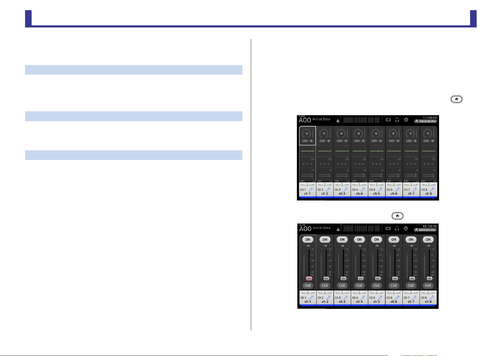
The display .............................................................................................................. 4
Universal operations ................................................................. 8
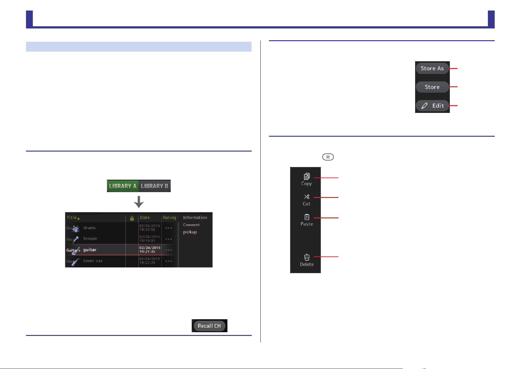
Library screen .......................................................................................................... 8
Keyboard screen .................................................................................................... 10
Menu .................................................................................................................... 10
Button and slider operations .................................................................................. 10
Toolbar.................................................................................... 11
SCENE screen ........................................................................................................ 11
METER screen ........................................................................................................ 13
RECORDER screen (INPUT/OUTPUT/TITLE LIST screen) .......................................... 14
MONITOR screen .................................................................................................. 18
SETUP screen (V3.0 and later)................................................................................ 21
LOGIN screen (V3.0 and later)............................................................................... 38
OVERVIEW screen.................................................................... 41
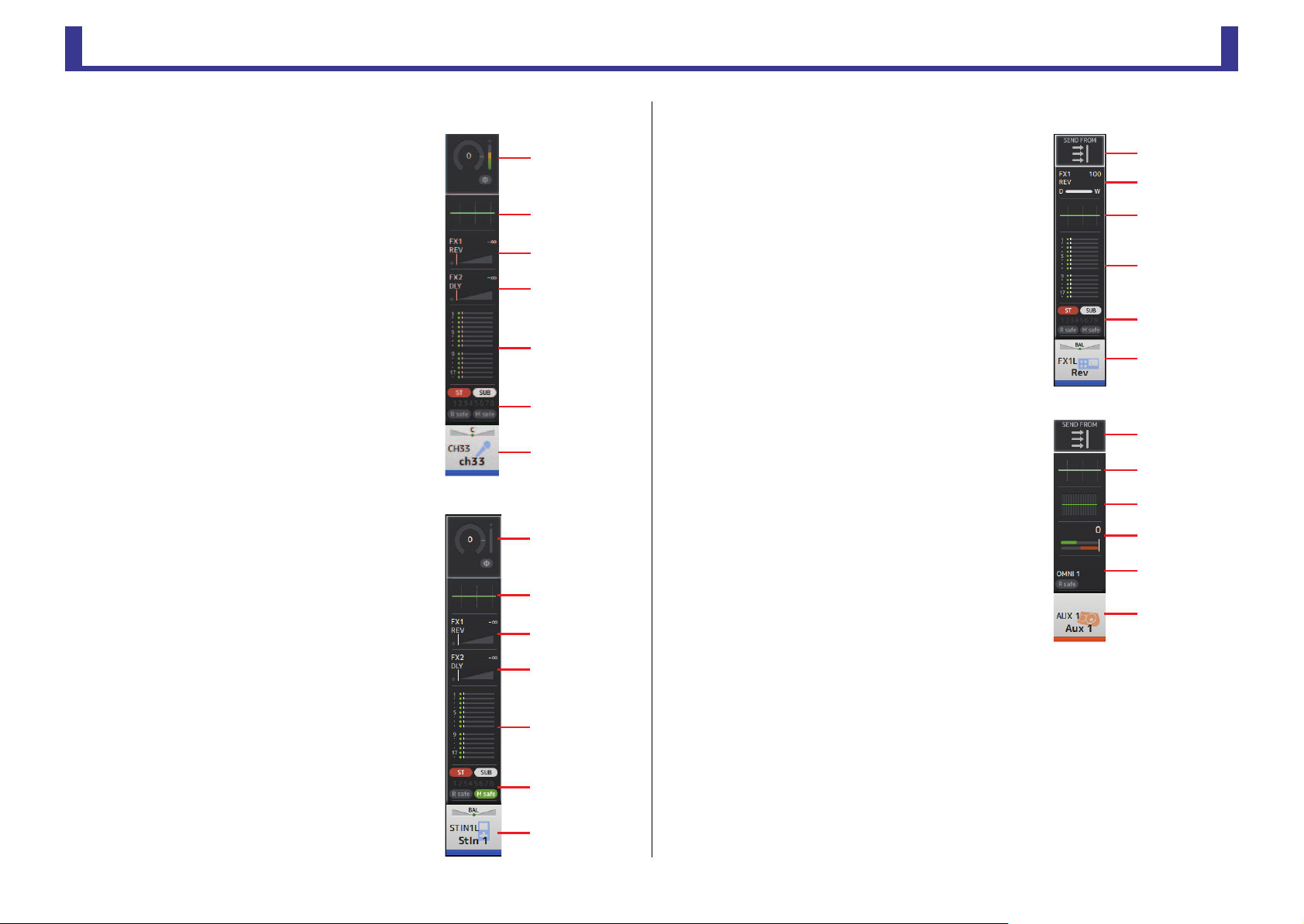
CH STRIP section ................................................................................................... 41
FADER section........................................................................................................ 43
Configuration screens............................................................. 46
INPUT screen......................................................................................................... 46
EQ screen .............................................................................................................. 48
GATE screen .......................................................................................................... 52
COMP screen ........................................................................................................ 54
FX screen (FX1/2, InsFX1–6) .................................................................................. 56
SEND TO AUX screen ............................................................................................ 61
ASSIGN screen....................................................................................................... 62
CH VIEW screen ..................................................................................................... 63
CH NAME screen ................................................................................................... 70
GEQ screen............................................................................................................ 71
OUTPUT screen ..................................................................................................... 73
SEND FROM screen ............................................................................................... 74
DCA ASSIGN screen............................................................................................... 75
DELAY screen (V2.5 and later)................................................................................ 77
Maintenance screen................................................................. 78
Initialize All Memory screen .................................................................................... 78
Initialize Current Memory screen ............................................................................ 79
Initialize NY64-D screen (V3.0 and later) ................................................................ 79
Input Port Trim screen............................................................................................ 80
Output Port Trim screen......................................................................................... 80
Fader Calibration screen (TF5/TF3/TF1) .................................................................. 81
Channel Color Calibration screen (TF5/TF3/TF1) .................................................... 82
Reference................................................................................. 83
List of parameters saved in Scenes and Presets........................................................ 83
Access limitation parameter list............................................................................... 89
Quick Config Input and input channel relationships ............................................... 91
Warnings and error messages ................................................................................. 93
Index........................................................................................ 95
Product dimensions................................................................. 97

Table of contents
Reference Manual
TF Series
-
3
-
Procedures
Recalling a Preset............................................................................................................. 9
Editing a Preset................................................................................................................ 9
Displaying configuration screens ................................................................................... 11
Saving the current settings as a new Scene.................................................................... 12
Recalling a Scene........................................................................................................... 12
Editing a Scene.............................................................................................................. 12
Setting the input ........................................................................................................... 15
Setting the output......................................................................................................... 16
Recording...................................................................................................................... 17
Playing back files stored on a USB storage device .......................................................... 18
Checking the input signals ............................................................................................ 19
Setting the oscillator...................................................................................................... 20
Using Recall safe function .............................................................................................. 25
Configuring settings in the PREFERENCE screen............................................................. 28
Assigning a feature to a [USER DEFINED KEY] ................................................................ 32
Assigning a feature to a [USER DEFINED KNOB] ............................................................ 32
Assigning a feature to the footswitch............................................................................. 33
Configuring the custom fader bank ............................................................................... 34
Recalling the CUSTOM FADER BANK (TF5/TF3/TF1) ...................................................... 34
Applying access permissions.......................................................................................... 40
Resetting user settings................................................................................................... 40
Loading user settings to other TF series consoles ........................................................... 40
OVERVIEW screen operations......................................................................................... 43
Copying settings from one channel and applying them to another channel .................. 44
Setting stereo link and the input source......................................................................... 47
Adjusting EQ in manual mode....................................................................................... 50
Adjusting EQ in 1-knob EQ mode.................................................................................. 50
Setting HPF ................................................................................................................... 51
Setting LPF .................................................................................................................... 51
Setting the gate............................................................................................................. 53
Setting the compressor.................................................................................................. 55
Setting an effect ............................................................................................................ 57
Setting an insert effect................................................................................................... 57
Adjusting the SEND TO AUX level.................................................................................. 62
Using GEQ .................................................................................................................... 72
Using faders to adjust GEQ (TF5/TF3/TF1)..................................................................... 72
Adjusting the SEND FROM level .................................................................................... 74
Adjusting the send level from AUX channels, STEREO channels,
and SUB channel to a MATRIX channel (V2.5 and later)..................................... 74
Assigning channels to a DCA group............................................................................... 76
Using the maintenance screen....................................................................................... 78
Calibrating the faders .................................................................................................... 81
If a fader must be calibrated again................................................................................. 81
Adjusting channel colors................................................................................................ 82

Overview
Reference Manual
TF Series
-
4
-
Overview
Using this document
You can search for keywords and view reference pages while using this document.
Searching for keywords
You can use the search function of your PDF viewing software to search for the desired text
within the document.
When using Adobe Reader, enter the desired text in the search bar and press your computer's
<Enter> key to begin the search.
Moving backward and forward in your viewing history
When viewing this document using Adobe Reader, you can easily move backward and
forward in your viewing history. This is particularly useful when you click a link to jump to
another page, and then want to return to the original page.
Using the index
An index of the keywords and topics in this document can be found on page 95. You can use
the index to easily jump to the desired explanation or topic.
The display
Here we will introduce the different screens displayed on the TF Series console display.
OVERVIEW screen
This screen is displayed when you first turn on the console.
From here you can move to other screens depending on the operations that you want to
perform.
You can return to the OVERVIEW screen at any time by pressing the Home key ( ).
For the TF5/TF3/TF1, the CH STRIP section is displayed.
For the TF-RACK, the FADER section is displayed. You can switch between the CH STRIP
section and FADER section by pressing the Home key ( ).
For more information about the OVERVIEW screen, see page 41.

Overview
Reference Manual
TF Series
-
5
-
Configuration screens
You can touch an area of the OVERVIEW screen to display the configuration screen for the
corresponding area.
1Toolbar (page 11)
Displays buttons for frequently used features. When you touch a button, the
corresponding configuration screen in the main area of the display.
2Navigation area
Allows you to select which screen is displayed in the main area of the display.
3Main area (page 46)
Displays the screen that you select using the toolbar or navigation area.
INavigation area
Displays the features of the currently selected channel.
You can drag the screen up and down to display other features.
CH1–CH32
1Displays the INPUT screen. (page 46)
2Displays the EQ screen. (page 48)
3Displays the GATE screen. (page 52)
4Displays the COMP screen. (page 54)
5Displays the FX1 screen. (page 56)
6Displays the FX2 screen. (page 56)
7Displays the SEND TO AUX screen. (page 61)
8Displays the ASSIGN screen. (page 62)
9Displays the CH VIEW screen. (page 63)
ձ
ճ
ղ
ձ
ղ
ճ
մ
յ
ն
շ
ո
չ

Overview
Reference Manual
TF Series
-
6
-
CH33–CH40
1Displays the INPUT screen. (page 46)
2Displays the EQ screen. (page 48)
3Displays the FX1 screen. (page 56)
4Displays the FX2 screen. (page 56)
5Displays the SEND TO AUX screen. (page 61)
6Displays the ASSIGN screen. (page 62)
7Displays the CH VIEW screen. (page 63)
STIN1/2
1Displays the INPUT screen. (page 46)
2Displays the EQ screen. (page 48)
3Displays the FX1 screen. (page 56)
4Displays the FX2 screen. (page 56)
5Displays the SEND TO AUX screen. (page 61)
6Displays the ASSIGN screen. (page 62)
7Displays the CH VIEW screen. (page 63)
FX RTN 1/2
1Displays the SEND FROM screen. (page 74)
2Displays the FX1 screen. (page 56)
3Displays the EQ screen. (page 48)
4Displays the SEND TO AUX screen. (page 61)
5Displays the ASSIGN screen. (page 62)
6Displays the CH VIEW screen. (page 63)
AUX1–AUX8
1Displays the SEND FROM screen. (page 74)
2Displays the EQ screen. (page 48)
3Displays the GEQ screen. (page 71)
4Displays the COMP screen. (page 54)
5Displays the OUTPUT screen. (page 73)
6Displays the CH VIEW screen. (page 63)
մ
ն
շ
ձ
ղ
ճ
յ
մ
ն
շ
ձ
ղ
ճ
յ
յ
ղ
ձ
ճ
մ
ն
ձ
ղ
ճ
մ
յ
ն

Overview
Reference Manual
TF Series
-
7
-
AUX9/10–AUX19/20
1Displays the SEND FROM screen. (page 74)
2Displays the EQ screen. (page 48)
3Displays the COMP screen. (page 54)
4Displays the INSFX screen. (page 56)
5Displays the OUTPUT screen. (page 73)
6Displays the CH VIEW screen. (page 63)
DCA1–DCA8
1Displays the DCA ASSIGN screen. (page 75)
2Displays the CH VIEW screen. (page 63)
STEREO
1Displays the EQ screen. (page 48)
2Displays the GEQ screen. (page 71)
3Displays the COMP screen. (page 54)
4Displays the OUTPUT screen. (page 73)
5Displays the CH VIEW screen. (page 63)
SUB
1Displays the SEND FROM screen. (page 74)
2Displays the EQ screen. (page 48)
3Displays the COMP screen. (page 54)
4Displays the OUTPUT screen. (page 73)
5Displays the CH VIEW screen. (page 63)
MATRIX1–MATRIX4
1Displays the SEND FROM screen. (page 74)
2Displays the EQ screen. (page 48)
3Displays the DELAY screen. (page 77)
4Displays the OUTPUT screen. (page 73)
5Displays the CH VIEW screen. (page 63)
մ
ն
ձ
ղ
ճ
յ
ձ
ղ
մ
ձ
ղ
ճ
յ
մ
ձ
ղ
ճ
յ
մ
ձ
ղ
ճ
յ

Universal operations
Reference Manual
TF Series
-
8
-
Universal operations
In this section we will introduce the screens that are displayed when you press the Library key
( ) and the Menu key ( ), which are found in the Display section of the console's top
panel.
Library screen
Allows you to recall saved Presets.
A Preset is a collection of settings that are customized for a certain type of input, microphone,
instrument, etc. By recalling a Preset, you can set up a channel quickly and easily according
to the type of input, and then fine-tune the settings to your specific needs. You can even save
your own Presets.
1Channel name
Displays the name of the channel.
2Category selection button
Allows you to select a category.
Presets that match the selected category are displayed in the Library list.
3Library selection button
Allows you to switch between the available Libraries. The Presets that are stored in the
selected Library are displayed in the list.
LIBRARY A: Displays the Presets stored in LIBRARY A.
LIBRARY B: Displays the Presets stored in LIBRARY B.
4List
You can click a header in the list to sort the items by that header. (List items cannot be
sorted by "Information".)
To select a Preset, simply touch it. The selected Preset is highlighted, and can then be
saved, recalled, or edited.
A lock icon is displayed or cleared each time you touch the column. When the icon
is displayed, the Preset is write-protected.
The date on which the Preset was last saved is displayed in the Date column.
5Recall on/off checkboxes
Allow you to determine which parameters will be recalled (checkbox on) and not be
recalled (checkbox off).
Input channels
HA: Analog/digital gain setting, phantom power on/off, phase setting
Input Select: Input source settings
Name: Channel name, icon, and color
AUX 1–8, STEREO channels
GEQ: GEQ settings
Name: Channel name, icon, and color
FX RTN, AUX9/10–AUX19/20 channels
FX: Effect settings
Name: Channel name, icon, and color
SUB, MATRIX1–4 channels
Name: Channel name, icon, and color
6Recall CH button
Recalls a Preset to the selected channel.
7Edit button
Touch this button to display the keyboard so you can edit the title and comment.
(Keyboard screenpage 10)
8Store button
Saves the settings for the current channel as a Preset. The settings will overwrite the
Preset selected in the Library list.
9Store As button
Saves the settings for the current channel as a new Preset.
Touch this button to display the keyboard so you can enter the Preset name. (Keyboard
screenpage 10)
0Preset number (V1.1 and later)
Displays the Preset number. The first number indicates the number of Presets in the
selected category (2), and the second number indicates the total number of Presets.
ձղ ճ պ
մ
յ
ն
շ
ո
չ

Universal operations
Reference Manual
TF Series
-
9
-
Displaying the Library screen from a configuration screen
When you display the Library screen from a configuration screen, one of the following buttons
is added to the Library screen, depending on the configuration screen you were using.
Recall EQ button
Displayed when you enter the Library from the EQ screen, and recalls EQ settings only.
Recall Gate button
Displayed when you enter the Library from the GATE screen, and recalls GATE settings only.
Recall COMP button
Displayed when you enter the Library from the COMP screen, and recalls COMP settings only.
Recall FX button
Displayed when you enter the Library from the FX screen, and recalls FX settings only.
Recall GEQ button
Displayed when you enter the Library from the GEQ screen, and recalls GEQ settings only.
Library screen menu
Press the Menu key ( ) from the Library screen to display the following items.
Recalling a Preset
1.
Touch a Library selection button to select the Library that contains the desired Preset.
A list of Presets is displayed.
You can click a header in the list to sort the items by that header. (List items cannot be sorted by
"Information".)
2. Touch the desired Preset.
The selected Preset is highlighted.
3. Select the items that will be recalled.
Turn the checkboxes on for items that you want to recall.
4. Touch the Recall CH button.
The Preset is recalled to the selected channel.
Preset list
Editing a Preset
1. Recall the desired Preset.
2. Touch the Edit button.
Display the keyboard so you can edit the title and comment.
(Keyboard screenpage 10)
Edit the desired items.
3. touch the Store or Store As button.
Store button: Saves the settings for the current channel as
a Preset. The settings will overwrite the Preset selected in
the Library list.
Store As button: Saves the settings for the current channel
as a new Preset.
1Copy
Copies the selected Preset.
2Cut
Cuts the selected Preset.
3Paste
Pastes the copied or cut Preset to the Library.
4Delete
Deletes the selected Preset.
Store As
button
Store button
Edit button
ձ
ղ
ճ
մ

Universal operations
Reference Manual
TF Series
-
10
-
Keyboard screen
Allows you to edit titles and comments.
1Cancel button
Discards any changes you made and returns to the previous screen.
2OK button
Saves the changes you made.
3Title field
Enter the name of the Scene here.
4Comment field
Enter comments about the Scene here.
5Keyboard
Touch to enter the desired text.
Menu
Displays a menu of options available in the current screen. The content of the menu varies
depending on which screen is being displayed. For information about each menu, refer to the
description for the corresponding page.
Button and slider operations
䐟䐠
䐡
䐢
䐣
Item Term Description
Close button [X] Touch to close the current screen.
OK button Applies the current settings.
Cancel button Cancels the operation and returns to the previous
screen.
Clear button Clears the information you entered.
Jump icon Displays the relevant screen.
Slider
Flashes in pink when you touch it to indicate it can be
operated.
You can then drag the slider on the display or turn the
[TOUCH AND TURN] knob to adjust the setting.
Pan slider Flashes in pink when you touch it to indicate it can be
operated by the [TOUCH AND TURN] knob.
Balance slider
Edit icon Displays the screen where you can edit information,
such as the keyboard screen.
Menu Touch a button with "M" displayed on it to display the
menu.
Text box
When you touch a text box that can accept values, it
flashes in pink to indicate that its content can be
changed.
Touch the box again to display the screen that allows
you to enter values.
You can also change the value by turning the
[TOUCH AND TURN] knob.
When you touch a text box that can accept text, the
keyboard screen is displayed.
When on (example):
When off (example): On and off Switches between on and off when you touch the
item.

Toolbar
Reference Manual
TF Series
-
11
-
Toolbar
Provides access to frequently used features and system settings.
The toolbar is displayed regardless of the screen content.
1Displays the SCENE screen.
2Displays the METER screen. (page 13)
3Displays the RECORDER screen. (page 14)
4Displays the MONITOR screen. (page 18)
5Displays the SETUP screen. (page 21) (V3.0 and later)
6Displays the current time. (page 36)
7Displays the LOGIN screen. (page 38) (V3.0 and later)
The name of the user that is currently logged in is displayed with the icon.
Additionally, the following items may be displayed to indicate the corresponding
status.
ACCESS: The console is accessing the USB storage device that is connected to its
USB connector.
CUE: The cue is turned on.
OSCILLATOR: The oscillator is turned on.
Quick Config: Quick Config is being used. (V2.0 and later)
SCENE screen
Allows you to manage previously saved mixer setups, or "Scenes".
When you recall a Scene, you can exempt certain settings from being replaced by the settings
contained in the Scene; this is called "recall safe".
1Scene list selection button
Allows you to switch between the available Scene lists.
SCENE A: Displays Scene list A.
SCENE B: Displays Scene list B.
2Scene list
Displays the Scenes saved in the selected Scene list.
You can click a header in the list to sort the items by that header. (List items cannot be
sorted by "Information".)
To select a Scene, simply touch it. The selected Scene is highlighted, and can then be
saved, recalled, or edited.
A green triangle is displayed next to the Scene that is currently recalled.
A lock icon is displayed or cleared each time you touch the column. When the icon
is displayed, the Scene is write-protected.
The date on which the Scene was last saved is displayed in the Date column.
Displaying configuration screens
When you touch an icon, the corresponding configuration screen is displayed.
To return to the previous screen, touch the icon again, or touch the close button ([X]) in the
upper right of the screen.
ձղճմյնշ
䐟䐠
䐡䐢 䐣

Toolbar
Reference Manual
TF Series
-
12
-
3Store button
Saves the current mixer setup and assigns it to the Scene number selected in the Scene
list.
Touch this button to display the keyboard so you can edit the title and comment.
(Keyboard screenpage 10)
4Recall button
Recalls the Scene that is selected in the Scene list.
5Edit button
Touch this button to display the keyboard so you can edit the title and comment.
(Keyboard screenpage 10)
Saving the current settings as a new Scene
1. Touch the Scene area of the Toolbar.
2. Touch a Scene list selection button to select the Scene list.
The Scene list is displayed.
3. Touch a blank Scene.
4. Touch the Store button.
Display the keyboard so you can edit the title and comment (Keyboard screenpage 10).
Enter the new Scene name and a comment.
5. Touch the OK button.
The settings will be saved as a new Scene.
Blank Scene
Recalling a Scene
1. Touch a Scene list selection button to select the
Scene list that contains the desired Scene.
The Scene list is displayed.
2. Touch the desired Scene.
The selected Scene is highlighted.
You can click a header in the list to sort the items by that header. (List items cannot be sorted by
"Information".)
3. Touch the Recall button.
The mixer settings saved in the Scene are recalled.
The name of the recalled Scene is displayed in the upper left
of the screen.
Editing a Scene
1. Select the Scene that you want to edit.
2. Touch the Edit button.
Display the keyboard so you can edit the title and comment (Keyboard screenpage 10).
Edit the desired items.
3. Touch the OK button.
The settings will overwrite the Scene selected in the Scene list.
Selected Scene

Toolbar
Reference Manual
TF Series
-
13
-
SCENE screen menu
Press the Menu key ( ) from the Scene screen to display the following items.
METER screen
Displays the input and output level of all the channels, and allows you to select the metering
point (i.e., the point at which the level is detected).
1Input metering point selection menu
Select the input level metering point from the menu.
PRE HPF: After the head amp; before the HPF
PRE FADER: Before the fader
POST ON: After the [ON] key
2Output metering point selection menu
Select the output level metering point from the menu.
PRE EQ: Before the EQ
PRE FADER: Before the fader
POST ON: After the [ON] key
3Peak Hold button
Turn this button on to hold the peak level for each level meter. Turn this button off to
remove the peak level that was being held. The Peak Hold on/off setting affects both
input and output channels.
1Copy
Copies the selected Scene.
2Cut
Cuts the selected Scene.
3Paste
Pastes the copied or cut Scene to the Scene list.
4Delete
Deletes the selected Scene.
ձ
ղ
ճ
մ
NOTE
You can assign the Peak Hold button to a [USER DEFINED KEY]. (page 29)
ձղճ
մ
յ

Toolbar
Reference Manual
TF Series
-
14
-
4Meters
Display the input and output levels of the channels.
5Meter display selection button
Allows you to select how many meters are displayed. Three display modes are available.
RECORDER screen (INPUT/OUTPUT/TITLE LIST
screen)
You can connect a USB storage device to the console's iPad connector and use the console
to record audio to the device, play back audio files stored on the device, and manage audio
files stored on the device.
When a USB storage device is connected to the iPad connector, your TF series console can
record its internal signals to the device as an audio file and play back files that are stored on
the device.
You can also connect an iOS device to the console and use your iPad or iPhone as an audio
input source for the mixer.
Recorded files are formatted as 48 kHz, 24-bit stereo WAV files.
Playback is supported for WAV and MP3 (MPEG-1 Audio Layer-3) files.
These features allow you to record signals from the STEREO and AUX buses to the USB
storage device, and use audio files that are saved on your iPad or USB storage device as the
source for the console's ST IN 1 channel.
մ
յ
մ
յ
մ
յ
NOTE
• Simultaneous recording and playback is not supported.
• While recording, the signal being recorded cannot be used as an INPUT channel.
• Compatible USB storage devices must be formatted in FAT32. If necessary, connect the device to the
USB connector (on the right side of the top panel) and use the contextual menu in the SAVE/LOAD
screen to format the device.
• Use only USB storage devices with a sector size of 512 bytes. (Certain large-capacity hard disk drives
may not be compatible with the console.)
• USB storage devices with an allocation unit size under 4096 bytes are not supported. (This may apply
to small-capacity USB memory devices.)
• For recording, we recommend using a high-speed device, such as a hard disk drive (HDD) or solid-state
drive (SSD). USB memory devices and iOS devices can be used for playback only.
• For playback, MP3 files must be encoded at 44.1 kHz or 48 kHz, with a bit rate of 128 kbps–320 kbps.
Files encoded using variable bit rate (VBR) can be played back, but file length and elapsed playback
time may not be displayed properly.

Toolbar
Reference Manual
TF Series
-
15
-
INPUT/OUTPUT screen
Allows you to configure inputs and outputs for playback and recording.
1RECORD source selection menu
Allows you to select the source that will be recorded.
The source selected here is also output to CH33 and CH34 of the USB TO HOST
connector.
2RECORD level meter
Displays the recording level.
3RECORD level slider
Adjusts the recording level.
4RECORD CUE button
Turns the recording source cue on and off.
5PLAYBACK level meter
Displays the playback level.
6PLAYBACK level slider
Adjusts the playback level.
7PLAYBACK CUE button
Turns the playback source cue on and off.
մշ
ձղճյն
NOTE
When an iPad or other iOS device is connected, "iOS device is connected. Use transport control on the
device." is displayed, and the playback button is not displayed. Use the corresponding app on the iOS
device to control playback.
Setting the input
1. Touch the RECORD source selection menu and select
the source you want to record.
2. Drag the RECORD level slider and adjust the recording
level.
RECORD level slider

Toolbar
Reference Manual
TF Series
-
16
-
TITLE LIST screen
When a USB storage device is connected to the console via the iPad connector, you can use
this screen to play back audio files saved on the device and record the signal from the 2MIX
source to the device.
1Parent directory button
Displays the directory that is one level above the current directory.
2Current directory
Displays the path of the current directory on the USB storage device.
3USB storage device information
Displays the volume name of the USB storage device.
The amount of available space (i.e., available capacity and available percentage of total
capacity) on the USB storage device is also displayed.
4File list
Displays a list of the files in the current directory.
You can click a header in the list to sort the items by that header.
Touch a file name to select the file for playback or editing.
Touch the music note icon to start and pause playback.
Files whose checkboxes are turned on will be played back-to-back during continuous playback.
The name of each file in the directory is displayed in the File Name column.
Artist information is displayed in the Artist column (MP3 files only) and the length of the
file is displayed in the Time column.
3. If you want to monitor the record source, touch the
RECORD CUE button to turn the cue on.
Setting the output
1. Drag the PLAYBACK level slider and adjust the playback
level.
2. Touch the PLAYBACK CUE button to turn the cue on.
PLAYBACK level slider
ձղ ճ
մ
յնշոչպջռս

Toolbar
Reference Manual
TF Series
-
17
-
5Follow playback button
When this button is turned on during continuous playback, the file that is currently
playing is highlighted in the file list.
6File information
When playing back an MP3 file, the file's bit rate and the current playback location are
displayed here.
When playing back a WAV file, the file's sample rate and the current playback location
are displayed here.
When recording, the WAV file's sample rate and the elapsed recording time are
displayed here.
7Playback mode selector button
You can select the desired playback mode.
Touch the button to toggle through the available modes.
: SINGLE playback; the file is played and then playback stops.
: SINGLE REPEAT; the file plays repeatedly until you stop playback.
: ALL; all files with checkboxes turned on in the file list are played back one after
another, and then playback stops.
: ALL REPEAT; all files with checkboxes turned on in the file list are played back one
after another, and then playback repeats until you stop playback.
8Previous button
Moves the playback location to the beginning of the current file or to the beginning of
the previous file.
9Stop button
Stops playback and recording.
0Play/pause button
Starts and pauses playback.
ANext button
Moves the playback location to the beginning of the next file.
BRecord button
Sets the console to record-ready mode.
CFile name edit button
Allows you to edit the file's name.
NOTE
When an iPad or other iOS device is connected, "iOS device is connected. Use transport control on the
device." is displayed, and the playback button is not displayed. Use the corresponding app on the iOS
device to control playback.
Recording
1. Connect a compatible USB storage device to the iPad connector.
2. Touch the record button.
The record button begins flashing to indicate that the console is in record-ready mode.
3. When you're ready to start recording, touch the play/pause button.
The record button remains lit during recording.
You can touch the play/pause button to pause and resume recording.
4. When you're ready to stop recording, touch the stop button.
The recorded file is named automatically based on the console's date and time setting.
5. If necessary, touch the file name edit button and change the file name.

Toolbar
Reference Manual
TF Series
-
18
-
RECORDER screen menu
Press the Menu key ( ) from the RECORDER screen to display the following items.
MONITOR screen
Allows you to manage cue and monitor signals and to control oscillators.
The CUE/MONITOR screen is used to control the signals that are monitored using
headphones and near-field monitors. Here you can select the sources that will be
continuously monitored, and select individual channels for monitoring using the CUE feature.
The OSCILLATOR screen is used to configure the oscillator and turn it on and off. The console
has a built-in oscillator that can output a sine wave or pink noise to the desired bus, allowing
you to check external devices or test the characteristics of a venue.
CUE/MONITOR screen
Allows you to monitor certain inputs using headphones or speakers. You can select which
sources will be monitored, change the monitor signal to mono, or add a delay.
1CUE mode button
Used to select the CUE mode.
Mix CUE: Enables cue for multiple channels.
Last CUE: Enables cue for the last channel selected.
2CUE point selection buttons
Selects the point in the signal path that will be monitored.
PFL: Before the fader
AFL: After the fader (inputs are PFL only)
3Mono button
Allows you to change the monitor signal to mono.
Playing back files stored on a USB storage device
1. Touch the file that you want to play in the file list.
To play a file stored in a different directory, touch the parent directory button and navigate to the
desired directory.
2. Touch the playback mode selector button and
select the desired mode.
3. Touch the play button.
Playback begins.
1Make Dir
Makes a new directory in the current directory.
2Delete
Deletes the selected file.
Selected fileParent directory button
Play button
Playback mode selector button
ձ
ղ
ձղճմյ
ն
շ
ո
չպ

Toolbar
Reference Manual
TF Series
-
19
-
4Delay button
Delays the monitor signal.
5Monitor output button
Turns the monitor output on and off.
The signal is output from the [PHONES] jack regardless of this setting.
6Monitor level meter
Displays the monitor level.
7Monitor level slider
Adjusts the monitor output level.
The signal is output from the [PHONES] jack regardless of this setting.
8Clear CUE button
Cancels all cue selections.
9Delay setting
Determines the delay time by specifying distance (meters or feet) or time (milliseconds).
Touch a text box to display the keyboard and enter a value. (page 10)
0Monitor selection buttons
Allow you to select the sources that will be monitored.
TF5/TF3/TF1
TF-RACK
Checking the input signals
1. Touch a CUE mode button to select
the desired cue mode.
2. Select the desired monitor sources by
touching the corresponding monitor
selection buttons.
3. Select the desired cue point by
touching the corresponding CUE
point selection button.
4. Touch the monitor output button to
turn the monitor output on and off.
5. Drag the monitor level slider to adjust
the monitor level.
6. Select the desired delay time.
Touch one of the delay setting text boxes to
display the keyboard. You can set the delay
time by specifying distance (meters and feet)
or time (milliseconds).
7. Touch the delay button.
The delay is turned on.
Monitor level
slider
Delay button
Delay setting
Tex t bo xe s

Toolbar
Reference Manual
TF Series
-
20
-
OSCILLATOR screen
Allows you to configure the oscillator.
1Oscillator mode button
Allows you to select the oscillator mode.
SINE WAVE: A sine wave will be output continuously.
PINK NOISE: Pink noise will be output continuously.
BURST NOISE: Pink noise will be output intermittently.
2Parameter sliders
Allows you to adjust parameters for the oscillator.
When the oscillator mode is set to SINE WAVE, this setting determines the frequency of
the sine wave.
When the oscillator mode is set to BURST NOISE, this setting determines the Width
(duration of the noise) and Interval (length of silence between noise bursts).
When the oscillator mode is set to PINK NOISE, nothing is displayed here.
3Oscillator output button
Turns the oscillator output on and off. When the oscillator is turned on, the oscillator
signal is sent to the input channels that are selected by the oscillator assignment
buttons.
4Oscillator output level slider
Adjusts the oscillator output level.
5Oscillator output meter
Displays the oscillator output level.
6Oscillator assignment buttons
Determine which channels the oscillator is sent to. You can select multiple channels.
ձղճ
մ
յն
Setting the oscillator
1. Touch the oscillator mode button and select the desired
mode.
2. Use the oscillator assignment buttons to determine
which channels the oscillator signal will be sent to.
3. Touch the oscillator output button to turn on
the oscillator output.
4. While referring to the oscillator output level
meter, drag the oscillator level slider to adjust
the oscillator output level.
When the oscillator mode is set to SINE WAVE, you can
also adjust the frequency of the oscillator.
When the oscillator mode is set to BURST NOISE, you
can also adjust Width (duration of each noise burst) and
the Interval (duration of each silence between noise
bursts).
Channel is selected
Oscillator
output button
Oscillator
level slider
Oscillator
output meter
This manual suits for next models
4
Table of contents
Other Yamaha Music Mixer manuals

Yamaha
Yamaha MC1204II User manual

Yamaha
Yamaha 01V User manual

Yamaha
Yamaha PM3500 User manual

Yamaha
Yamaha KM802 User manual

Yamaha
Yamaha 02R96 VCM User manual

Yamaha
Yamaha EM-1400 User manual

Yamaha
Yamaha GA24/12 User manual

Yamaha
Yamaha AM602 User manual

Yamaha
Yamaha MG16/6FX User manual

Yamaha
Yamaha CL5 Instructions and recipes

Yamaha
Yamaha EMX3500 User manual

Yamaha
Yamaha MR842 User manual

Yamaha
Yamaha DS2416 User manual

Yamaha
Yamaha PM3500 User manual

Yamaha
Yamaha DM 1000 User manual

Yamaha
Yamaha MC802 User manual

Yamaha
Yamaha EMX 5000-12 User manual

Yamaha
Yamaha EMX88S User manual

Yamaha
Yamaha MW12 User manual

Yamaha
Yamaha AG06 User manual