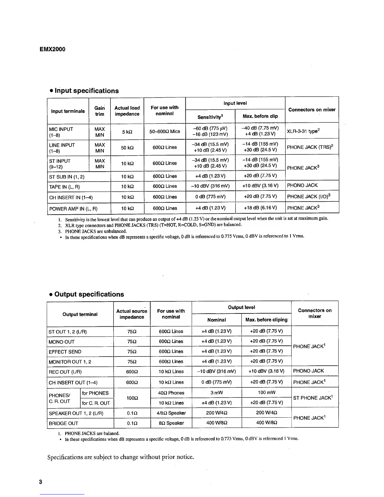
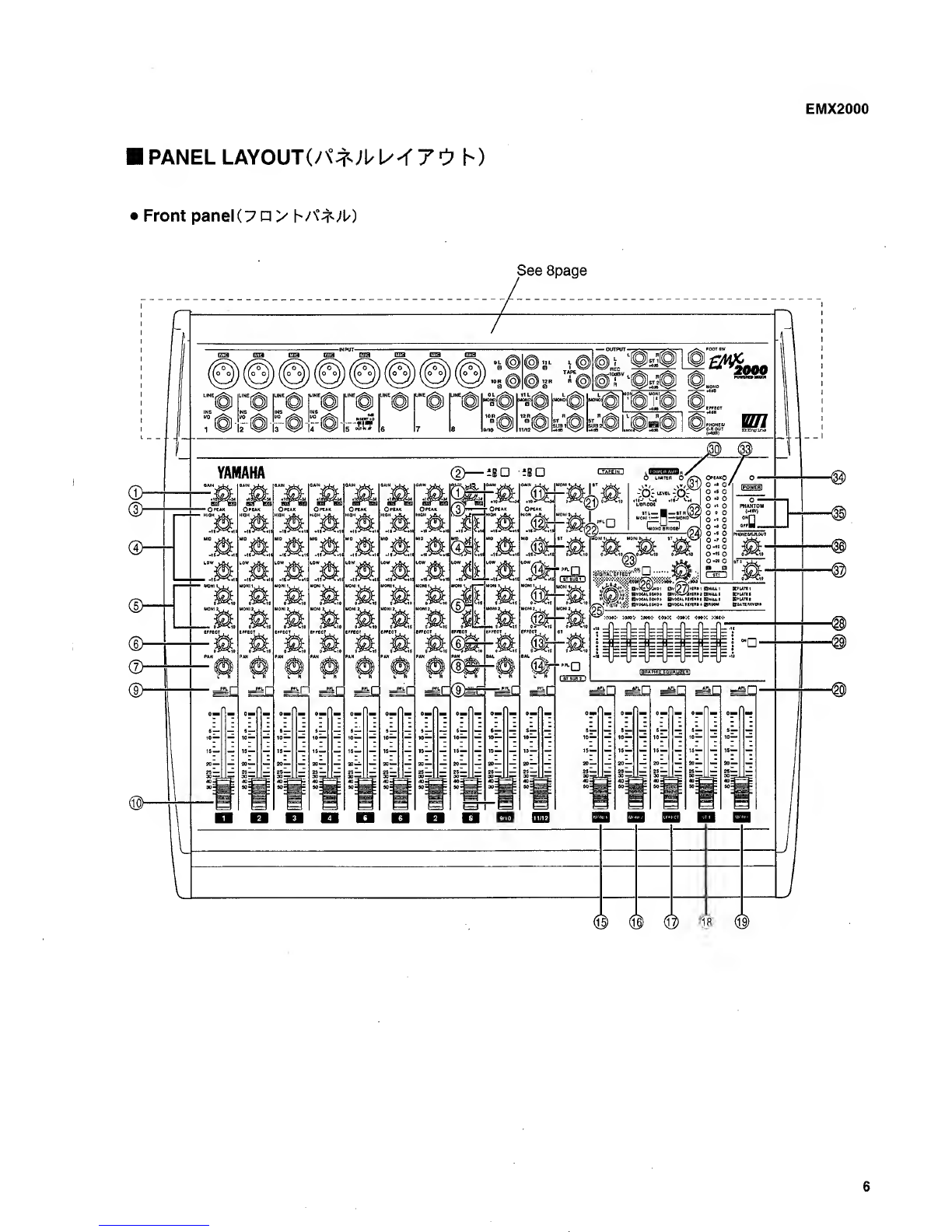
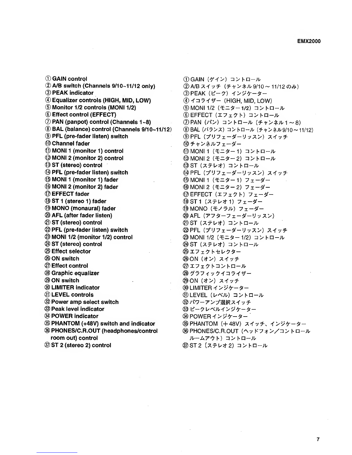
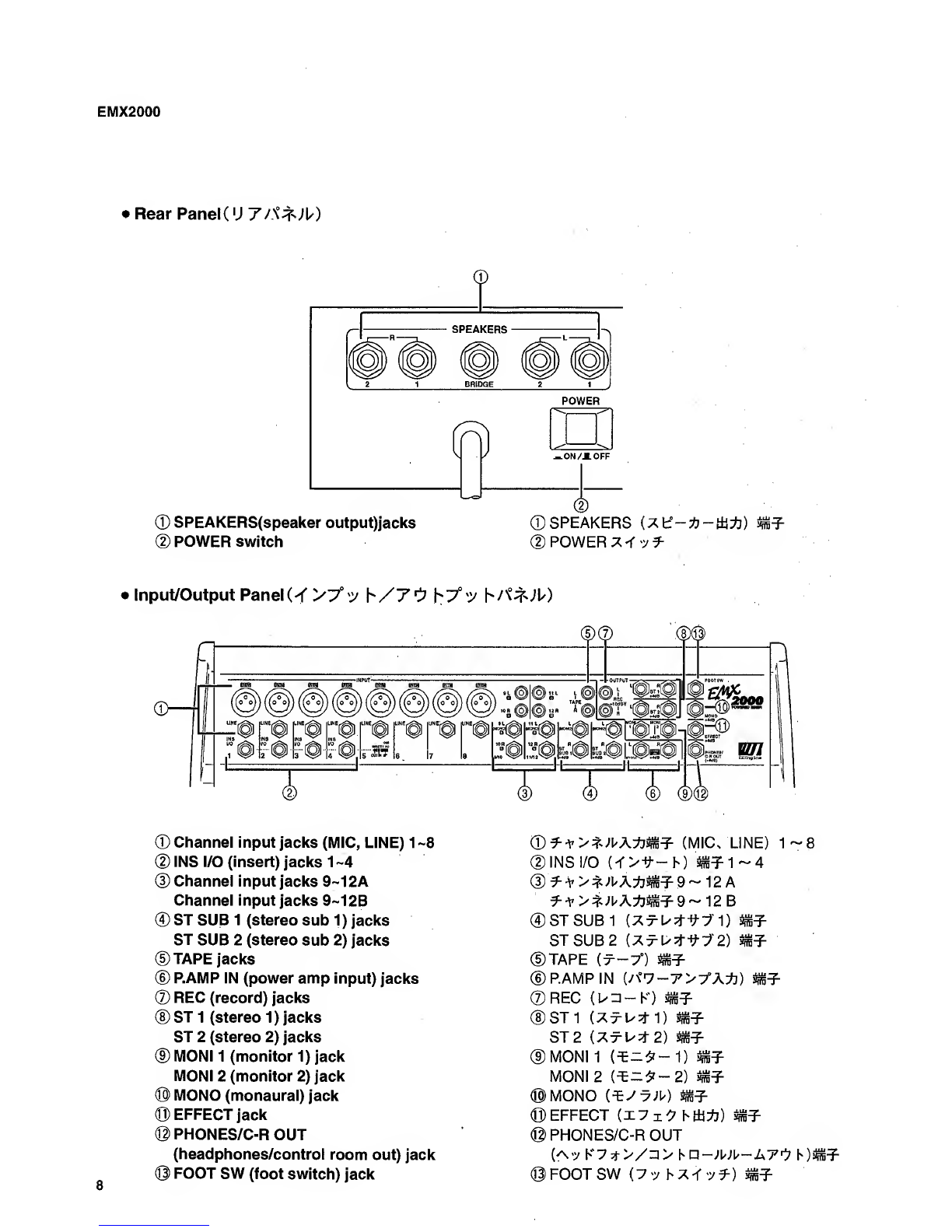
Yamaha EMX 2000 User manual
Other Yamaha Music Mixer manuals

Yamaha
Yamaha QL Series User manual

Yamaha
Yamaha LS9 Editor User manual

Yamaha
Yamaha EMX 600 User manual

Yamaha
Yamaha DMR8 User manual

Yamaha
Yamaha n8 User manual

Yamaha
Yamaha EMX62M User manual

Yamaha
Yamaha O1V96 User manual

Yamaha
Yamaha PM-2000 User manual

Yamaha
Yamaha M2500-24 User manual

Yamaha
Yamaha 01V User manual

Yamaha
Yamaha EMX620 User manual

Yamaha
Yamaha MG10XUF User manual

Yamaha
Yamaha TF5 User manual

Yamaha
Yamaha EM-1400 User manual

Yamaha
Yamaha MC1204 User manual

Yamaha
Yamaha DM 2000 Version 2 User manual

Yamaha
Yamaha SB168-ES User manual

Yamaha
Yamaha MG12XU User manual

Yamaha
Yamaha 007POTO-G0 User manual

Yamaha
Yamaha UW500 Assembly instructions


Popular Music Mixer manuals by other brands


Studiomaster
Studiomaster Air Pro 24 instruction manual

Pioneer
Pioneer SVM 1000 - Audio/Video Mixer Service manual

Roland
Roland M-160 owner's manual

Ecler
Ecler MAC40v user manual

Pioneer
Pioneer DJM 909 - Battle Mixer W/Effects operating instructions

Veeder-Root
Veeder-Root TLS-350 Series System setup manual