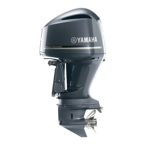
Yamaha 6X9 DIGITAL ELECTRONIC CONTROL User manual

To the owner
Thank you for selecting the 6X9 Digital Electronic Control (DEC) system. This operation manual
contains information needed for proper operation. A thorough understanding of these simple
instructions will help you obtain maximum enjoyment from your new Yamaha.
The maneuvering performance of some boats, when operating in joystick mode, may be adversely
affected by high winds and currents.
This manual also includes Autopilot and Joystick operations when upgrading to the full HELM MAS-
TER EX system. Please refer to the manual of the MFD gauge for detailed operation.
Yamaha continually seeks advancements and makes changes in product design and quality without
notice. Therefore, while this manual contains the most current product information available at the
time of printing, there may be minor discrepancies between the actual system and this manual. If
you have any questions about the operation of your 6X9 Digital Electronic Control system, please
consult a Yamaha dealer.
This operation manual is described only for the quint engine application.
Important information, within this manual, is identified in the following ways:
: This is the safety alert symbol. It is used to alert you to potential personal injury hazards.
Obey all safety messages that follow this symbol to avoid possible injury or death.
A WARNING indicates a hazardous situation which, if not avoided, could result in death or
serious injury.
A NOTICE indicates special precautions that must be taken to avoid damage to the products
or other property.
TIP:
A TIP provides key information to make procedures easier or clearer.
6X9 DIGITAL ELECTRONIC CONTROL (DEC)
(QUINT ENGINE)
OPERATION MANUAL
©2021 by Yamaha Motor Co., Ltd.
1st Edition, July 2021
All rights reserved.
Any reprinting or unauthorized use
without the written permission of
Yamaha Motor Co., Ltd.
is expressly prohibited.
Printed in Japan
LIT-18626-13-55
6X9-28199-90
DEC_OM(QUINT)_EN.book 3 ページ 2021年6月25日 金曜日 午前9時16分
Downloaded from ManualsNet.com search engine

CONTENTS
Alert message information ...................................................1
General information ..............................................................6
List of abbreviations .......................................................................... 6
Read labels and related manuals ..................................................... 6
ELECTRONIC KEY SWITCH (EKS) ......................................7
Basic information ............................................................................... 7
POWER switch ................................................................................. 10
START/STOP switch ........................................................................ 11
All START/STOP switch .................................................................. 11
Engine shut-off switch .................................................................... 12
Smart key settings ........................................................................... 12
Password card ...........................................................................................12
Changing the password .............................................................................13
Special mode .............................................................................................16
Adding a new key fob ................................................................................20
Replacing the battery in the key fob .............................................. 21
Information required by radio laws ................................................ 23
Remote control box ............................................................27
DEC alert indicator ........................................................................... 28
Remote control levers ..................................................................... 28
Adjusting the friction of the levers ................................................. 30
Adjusting the detent of the levers .................................................. 33
Neutral hold switch .......................................................................... 35
Single lever switch ........................................................................... 35
CENTER engine switch ................................................................... 37
Speed control ................................................................................... 40
Station selector switch (for dual station) ...................................... 41
Power trim/tilt (PTT) switch ............................................................. 41
Trim Assist All .................................................................................. 43
Trim Assist Center ........................................................................... 44
Autopilot (Upgradable) .......................................................47
Heading Sensor Operation .............................................................. 48
Heading Sensor Calibration .......................................................................48
DEC_OM(QUINT)_EN.book 1 ページ 2021年6月25日 金曜日 午前9時16分
Downloaded from ManualsNet.com search engine

Joystick (Upgradable) .........................................................49
Basic information ............................................................................. 49
Joystick ............................................................................................. 53
Maneuvering with the joystick ....................................................................54
Joystick switch ................................................................................ 55
Joystick calibration ......................................................................... 55
SetPoint switches (STAYPOINT/DRIFTPOINT/FISHPOINT) ......... 56
Plus (+) button/minus (-) button ..................................................... 59
SetPoint functions ........................................................................... 60
Changing the position of your boat in SetPoint mode ................. 62
Autopilot Operation ............................................................64
Basic information ............................................................................. 64
Adjusting the Autopilot sensitivity ................................................. 68
HEADING HOLD ............................................................................... 69
COURSE HOLD ................................................................................ 71
TRACK POINT .................................................................................. 74
PATTERN STEER ............................................................................. 78
Information required by radio laws .............................................................79
DEC_OM(QUINT)_EN.book 2 ページ 2021年6月25日 金曜日 午前9時16分
Downloaded from ManualsNet.com search engine
1
Alert message information 2
This section contains 6X9 Digital Electronic Control (DEC) system alert information that will be dis-
played on the MFD. Refer to MFD operation manual for additional information.
The MFD will display a window and alert icons to notify the operator when abnormalities in the 6X9
Digital Electronic Control system occur. A window will also be displayed when specific alert condi-
tions occur.
When events requiring multiple windows occur, the window with the highest priority (red alert) is dis-
played first.
There are 2 types of windows, “Alert Notifications,” and “Other Notifications,” each displayed with its
own color.
Alert notifications: Red
Other notifications: Yellow
Alert notifications
Observe the following instructions for responding to each specific alert.
Displayed if the boat cannot maintain its course during SetPoint.
Displayed if the boat cannot maintain its course during COURSE HOLD, DRIFTPOINT TRACK, or
TRACK POINT.
Displayed if the boat cannot maintain its heading during HEADING HOLD, DRIFTPOINT or STAY-
POINT
Displayed if SetPoint cannot be controlled because GPS signal is unstable.
Confirm
Position could not be maintained.
Confirm
Course could not be maintained.
Confirm
Headingcould not be maintained.
Confirm
GPSisunstable. Point Control deactivated.
DEC_OM(QUINT)_EN.book 1 ページ 2021年6月25日 金曜日 午前9時16分
Downloaded from ManualsNet.com search engine
2
Displayed if the boat cannot maintain its position during SetPoint control.
Displayed if battery connection is abnormal.
Displayed if a problem occurred in 6X9 Digital Electronic Control system. Turn off electric power,
wait 20 seconds, and then turn electric power on again.
Displayed if a problem occurred at active station. If you have multiple stations, change the station.
Displayed if the steering system is un-calibrated or failed.
Displayed if the steering sensor is un-calibrated or calibration has failed. Do steering calibration
again. Consult a Yamaha dealer.
Yes
No
Position could not be maintained.
Return to set point?
CHECK SYSTEM
Confirm
- Port Engine -
Check battery and wiring.
CHECK SYSTEM
Confirm
- Port Engine -
System configuration fault.
Reset SteeringSystem
Turn off main power for 20 seconds. Turn back on.
CHECK SYSTEM
Confirm
- Port Engine -
Active helm station fault.
If dual station system isused, change the station.
CHECK SYSTEM
Confirm
- Port Engine -
Steeringcalibration needed.
CHECK SYSTEM
Confirm
- Port Engine -
Calibration failure.
Perform steeringcalibration again.
DEC_OM(QUINT)_EN.book 2 ページ 2021年6月25日 金曜日 午前9時16分
Downloaded from ManualsNet.com search engine
3
Displayed if all engines’ steering systems do not move properly. Consult a Yamaha dealer.
Displayed if a problem occurred in the engine system. Consult a Yamaha dealer.
Confirm
Shift to neutral!
Emergency steer procedure:
Use engine’
Consult Yamaha dealer.
STEERING MALFUNCTION
- Port Engine -
smanual override lever to steer.
Confirm
Shift to neutral!
Emergency steer procedure:
Use Forward and Reverse to steer.
Consult Yamaha dealer.
STEERING MALFUNCTION
- Port Engine -
CHECK SYSTEM
Confirm
- Port Engine -
Consult Yamaha dealer.
DEC_OM(QUINT)_EN.book 3 ページ 2021年6月25日 金曜日 午前9時16分
Downloaded from ManualsNet.com search engine
4
Other notifications
Displayed if running a single engine for more than one hour. Start all engines to recharge the batter-
ies.
Displayed if GPS signal is interrupted and speed control stopped functioning.
Displayed if target position is changed while boat is moving during SetPoint.
Displayed if GPS signal is interrupted and maneuvering control could not be done.
Displayed when boat decelerates after determining final destination of TRACK POINT has been
reached.
Displayed when deceleration during TRACK POINT has finished. (When boat stops at final destina-
tion)
Confirm
Start all enginesto recharge
Battery Charge Low
Confirm
GPSisunstable. Speed control cannot be activated.
Confirm
Boat ismovingtoward new target.
Confirm
Boat control function hasbeen cancelled.
Confirm
Deceleration mode isactive.
Confirm
Deceleration finished.
Shift all leversto neutral.
DEC_OM(QUINT)_EN.book 4 ページ 2021年6月25日 金曜日 午前9時16分
Downloaded from ManualsNet.com search engine
5
Displayed when deceleration during TRACK POINT has finished. (When boat does SetPoint control
at final destination)
Displayed when TRACK POINT was turned on after setting route on MFD with no final destination
information.
Displayed if GPS signal is unstable. If this situation continues, the Autopilot function will be can-
celled and boat speed will be reduced.
Confirm
Deceleration finished.
To activate Set Point, shift all leversto neutral.
Confirm
When Final Track Point isreached, deceleration
mode isengaged. If necessary, operate control
lever before Final Track Point.
Confirm
GPSisunstable.
Boat control may be deactivated soon.
Speed Control: Move remote control lever.
Autopilot: Turn steeringwheel.
DEC_OM(QUINT)_EN.book 5 ページ 2021年6月25日 金曜日 午前9時16分
Downloaded from ManualsNet.com search engine
List of abbreviations
6
General information 3
List of abbreviations
The following list contains abbreviations displayed or used throughout this manual.
Read labels and related manuals
Before operating or working on this system:
• Read all labels carefully on the 6X9 Digital Electronic Control (DEC) system components.
• Read this manual thoroughly and see other related manuals for outboard motors, MFD and boats
for their basic operations.
If you need any additional information, contact your Yamaha dealer.
Abbreviation Description
DN Down side
EKS Electronic Key Switch
FForward
LED Light Emitting Diode
MFD Multi Function Display
NNeutral
NMEA National Marine Electronics Association
PORT Port side
PTT Power Trim and Tilt
RReverse
STBD Starboard side
UP Up side
DEC_OM(QUINT)_EN.book 6 ページ 2021年6月25日 金曜日 午前9時16分
Downloaded from ManualsNet.com search engine
Basic information
7
ELECTRONIC KEY SWITCH (EKS) 4
Basic information
5 m
Near
5 m
Key fob
Unlock Button
Lock Button
Key fob
LED
CR 2025
3V
Pushing the lock button.
HOW TO LOCK
3
Pushing the “POWER” switch.
HOW TO UNLOCK (Pattern 1)
Pushing the unlock button.
HOW TO UNLOCK (Pattern 2)
1
2
4
3
1
2
3
1
2
EKS
Lock No
Yes
Unlock
Number of
beeps
Engine can be
started Lock indicator
TIP:
・The key fob LED turns on when the key fob is used
・Recommended battery: CR2025
N
5 m Near
Key fob within 5 m (16 ft)
Number of beeps
Key fob at the console area
BlinkNeutral
position
Push Turned on Turn off
The EKS consists of the EKS panel and the key fobs. EKS functions: EKS locking/unlocking using key fobs, power
switch ON/OFF and engine starting and stopping.
Pressing the All start/stop switch will start or stop all engines.
DEC_OM(QUINT)_EN.book 7 ページ 2021年6月25日 金曜日 午前9時16分
Downloaded from ManualsNet.com search engine

Basic information
8
P: PORT
CP: CENTER PORT
C: CENTER
CS: CENTER STBD
S: STBD
N
Neutral
position
Push Turn offTurned on
Main / 2nd station
N
1
2
3
HOW TO STOP
START/STOP switch
Pushing the “START/STOP” switch starts
and stops engine.
ALL START/STOP switch
Pushing the ALL “START/STOP” switch
starts and stops all engines.
POWER switch
Pushing the “POWER” switch turns the
power to each engine ON and OFF.
HOW TO START
2
3
4
1
N
START/STOP panel
STBD
CENTER STBD
CENTERPORT
ALL START/STOP panelPOWER panel
START/STOP switch
(ALL)
LED
POWER switch
Lock indicator
CENTER PORT
Main station 2nd station
DEC_OM(QUINT)_EN.book 8 ページ 2021年6月25日 金曜日 午前9時16分
Downloaded from ManualsNet.com search engine
Basic information
9
The key fob system uses weak radio waves. The key fob system may not work in the follow-
ing situations.
For emergencies, EKS key fob floats and is water-resistant. All attempts should be made to
keep the EKS key fob dry and away from water, however. Operators are cautioned to
removed EKS key fob from pockets before entering the water.
• The key fob is placed in a location exposed to strong radio waves or other electromagnetic
noise.
• There are facilities nearby that are emitting strong radio waves (TV or radio towers, power
plants, broadcasting stations, airports, etc.).
• You are carrying or using communication equipment such as radios or mobile phones in
close proximity of the key fob.
• The key fob is in contact with or covered by a metallic object.
• Other boats equipped with a key fob system are nearby.
• The key fob is near the MFD, gauges, or a marine radio.
In such situations, move the key fob to another location and perform the operation again. If it still
does not work, operate the vehicle in emergency mode.
• Do not store the key fob in direct sunlight or in very hot locations.
• Do not drop the key fob or subject it to powerful shocks or place heavy objects on it.
• To clean the key fob, use a clean, soft, dry cloth to wipe it. Do not use cleaners, alcohol, or
other chemicals, to clean the key fob.
TIP:
• The EKS system can only be operated by a key fob that is registered as authorized in the receiver.
This is because the receiver recognizes and accepts only signals from a transmitter that is regis-
tered as authorized. If your key fob does not work, consult a Yamaha dealer.
• Replace the initial key fob battery one year after purchase, and then replace it every two years
from the second and following years.
• Dispose of the used batteries correctly according to the rules in your region.
• You can register up to six key fobs in the EKS system. For details, consult a Yamaha dealer.
• Be sure to lock the EKS when leaving the boat, or when leaving the operator’s seat if children are
nearby. Also, check that the lock indicator is turned ON.
• Repeatedly using a key fob to lock/unlock the system may cause the key fob to malfunction. When
you use a key fob for locking or unlocking the system, after you move the key fob away from the
lock indicator, wait at least one second before doing another lock or unlock operation.
• When locking/unlocking with the key fob, do not place the key close to devices possessing a mag-
netic field (magnets), as this may prevent the lock/unlock operation.
• When operating or stopping the boat, be sure to carry the key fob with you and be careful not to lose it.
• If any key fob is lost, be sure to have a Yamaha dealer delete the registration of the lost key num-
ber for security reasons.
• While operating the POWER switch or START/STOP switch, do not turn the steering wheel or per-
form any system operations at the same time, otherwise unexpected errors may occur.
• Interference from other electronic devices (radios) could affect locking and unlocking of the sys-
tem. Confirm the EKS has locked before leaving the boat. Repeat the locking/unlocking procedure
if necessary.
DEC_OM(QUINT)_EN.book 9 ページ 2021年6月25日 金曜日 午前9時16分
Downloaded from ManualsNet.com search engine

POWER switch
10
POWER switch
Pushing the power switch turns the power to
each engine ON and OFF. When the power is
ON, the LED will be illuminated.
How to lock
1. Hold the key fob within 5 m of the
POWER panel.
2. Press the lock button on the key fob.
3. The lock indicator on the POWER switch
turns on, and the system locks.
TIP:
• Locking cannot be done automatically.
Always use the key fob to lock the system.
• Only operates when the POWER switch is
off.
• The smart key LED turns on when the key
fob is used.
How to unlock (Pattern 1)
1. Place the key fob at the console area.
2. Press the POWER switch.
3. The lock indicator turn off, and the
POWER switch turns on. (LED turns on)
1. Lock indicator
2. LED
How to unlock (Pattern 2)
1. Hold the key fob within 5 m of the
POWER panel.
2. Press the Unlock button on the key fob.
1. Lock indicator
2. LED
3. Key fob
4. Lock button
5. Unlock button
Recognition succeeded
Power panel
12
EKS
Number
of
beeps
Engine
can be
started
Lock
indicator
Lock No Turned on
Unlock Yes Turn off
Lock Unlock
1212
5
4
2
3
DEC_OM(QUINT)_EN.book 10 ページ 2021年6月25日 金曜日 午前9時16分
Downloaded from ManualsNet.com search engine

START/STOP switch
11
START/STOP switch
Pushing the START/STOP switch starts and
stops each engine. The LED will be illumi-
nated when the engine is running.
How to start
1. Place the key fob near the POWER
panel.
2. Press the POWER switch.
TIP:
If you push the POWER switch, and the beep
sounds more than twice, request an inspec-
tion and repairs at a Yamaha dealer.
3. The lock indicator turn off, and the
POWER switch turns on. (LED turns on)
1. Lock indicator
2. LED
4. You can press the “START/STOP” switch
to start the engines.
How to stop
1. You can press the “START/STOP” switch
to stop the engines.
2. Press the “POWER” switch.
1. “START/STOP” switch
2. “POWER” switch
All START/STOP switch
Pushing the All START/STOP switch starts
and stops all engines. The LEDs will be illu-
minated when the engines are running.
Number of beeps
Recognition
succeeded
Recognition failed More than
POWER panel
POWER panel
12
START/STOP panel
POWER panel
1
2
DEC_OM(QUINT)_EN.book 11 ページ 2021年6月25日 金曜日 午前9時16分
Downloaded from ManualsNet.com search engine
Engine shut-off switch
12
Engine shut-off switch
The clip must be attached to the engine shut-
off switch for the engines to run. The cord
should be attached to a secure place on the
operator’s clothing, or arm or leg. Should the
operator fall overboard or leave the helm, the
cord will pull out the clip, turning all engines
OFF. This will prevent the boat from running
away under power.
Attach the engine shut-off cord to a
secure place on your clothing, or your
arm or leg while operating. Do not attach
the cord to clothing that could tear loose.
Do not route the cord where it could
become entangled, preventing it from
functioning. Avoid accidentally pulling the
cord during normal operation. Loss of
engine power means the loss of most
steering control. Also, without engine
power, the boat could slow rapidly. This
could cause people and objects in the
boat to be thrown forward.
1. Engine shut-off switch
2. Clip
3. Engine shut-off cord (lanyard)
Smart key settings
Password card
The key fob is provided with two cards on
which are written its factory default. Keep
these cards in safe places, because you will
need one of them to start the engine if the
key fob is lost or malfunctions, or its battery
fails.
TIP:
If you change the password, the factory
default that is provided is disabled.
1. Factory default
1
2
3
1
DEC_OM(QUINT)_EN.book 12 ページ 2021年6月25日 金曜日 午前9時16分
Downloaded from ManualsNet.com search engine
Smart key settings
13
Changing the password
You can add a new key fob or change the password to unlock the system if the smart key is lost.
TIP:
• The procedure to change the password in “How to set (how to enter setting mode)”, and when the
recognition succeeded beep sounds, move to “How to set (how to set passwords)”.
• If you change the password, the factory default that is provided is disabled.
How to set (how to enter setting mode)
1. Use the key fob to lock the system. (The lock indicator turns on)
2. Press the POWER switch repeatedly on and off three times. After that, a beep sounds two
times.
How to set (how to set passwords)
1. Repeat steps 1 and 2 three times.
2. The password input mode activates and a beep sounds.
3. Press the POWER switch once to start the password beep.
4. Set the first digit “” of the password.
Press the POWER switch, while the beep is beeping, when it reaches the number of beeps that
is equal to the number you want for this digit of your password.
How the beep sounds:
_________
ON OFF
Beep
Long press for more than
3 seconds
Release for more than
3 seconds Recognition succeeded
Number of beeps
When recognition succeeds
DEC_OM(QUINT)_EN.book 13 ページ 2021年6月25日 金曜日 午前9時16分
Downloaded from ManualsNet.com search engine
Smart key settings
14
5. After the first digit is set, press the POWER switch to start setting the second digit of your pass-
word.
6. Set the second digit “” of the password.
Press the POWER switch, while the beep is beeping, when it reaches the number of beeps that
is equal to the number you want for this digit of your password.
How the beep sounds:
_________
7. After the second digit is set, press the POWER switch to start setting the third digit of your pass-
word.
8. Set the third digit “” of the password.
Press the POWER switch, while the beep is beeping, when it reaches the number of beeps that
is equal to the number you want for this digit of your password.
How the beep sounds:
_________
9. After the third digit is set, press the POWER switch to start setting the fourth digit of your pass-
word.
DEC_OM(QUINT)_EN.book 14 ページ 2021年6月25日 金曜日 午前9時16分
Downloaded from ManualsNet.com search engine
Smart key settings
15
10. Set the fourth digit “” of the password.
Press the POWER switch, while the beep is beeping, when it reaches the number of beeps that
is equal to the number you want for this digit of your password.
How the beep sounds:
_________
11. After the fourth digit is set, the POWER switch turns on, and the change is complete.
12. Beeps sound indicating the new password.
TIP:
• A short beep sounds 10 times according to the numbers in the password (password: 1, 2, 3, 4, 5,
6, 7, 8, 9, 0).
• When setting the numbers in the password, the beep sounds differently for the selection of each
digit, first through fourth.
• Even if you forget the password you pressed in the first round, after the password beep sounds 10
times, you can input your password again. However, if there is no input by the third round, the
mode is shutdown.
Number of beeps
Recognition succeeded
Recognition failed
Number of
beeps First Second Third Fourth Fifth Sixth Seventh Eighth Ninth Tenth
Password
number 1234567890
Sound of beep for first digit of password
(short beep 1 time x 10)
_________
Sound of beep for second digit of password
(short beep 2 times x 10)
_________
Sound of beep for third digit of password
(short beep 3 times x 10)
______
___
Sound of beep for fourth digit of password
(short beep 4 times x 10)
_____
____
DEC_OM(QUINT)_EN.book 15 ページ 2021年6月25日 金曜日 午前9時16分
Downloaded from ManualsNet.com search engine
Table of contents
Other Yamaha Outboard Motor manuals
Popular Outboard Motor manuals by other brands

SELVA MARINE
SELVA MARINE Blue Whale 250 EFI Service manual

TOHATSU
TOHATSU M 6B owner's manual

Side-Power
Side-Power SP 300 HYDSH420/386TC Installation and user manual

TOHATSU
TOHATSU M 60C owner's manual

Hidea
Hidea F15 owner's manual

Torqeedo
Torqeedo Cruise 12.0 FP TorqLink Translation of the original operating instructions

MINN KOTA
MINN KOTA Endura C2 50 user manual

Yanmar
Yanmar SD25 Operation manual

Briggs & Stratton
Briggs & Stratton AA0101 Operating & maintenance instructions

Briggs & Stratton
Briggs & Stratton 5 HP Troubleshooting & repair manual

MINN KOTA
MINN KOTA FORTREX user manual

SLEIPNER MOTOR AS
SLEIPNER MOTOR AS SE 40 Installation and user manual