Yamaha YS928J User manual

Read this manual carefully before operating this machine.
7VY-28199-70
YS928J
Snowblower
OWNER’S MANUAL
7VY-9-70_hyo.indd 1 2010/05/07 9:19:39

Congratulations on your purchase of your new Yamaha.
This manual will provide you with a good basic understanding of the operation and mainte-
nance of this machine.
If you have any questions regarding the operation or maintenance of your machine, please
consult a Yamaha dealer.
* Some illustrations and text shown in this manual may differ from the actual model due to
changes in specifications or other reasons.
* Take care of this manual. Please attach this manual to the product when it is lent or trans-
ferred to another person.
* When depositing the product, batteries, oil or other components, consult your Yamaha
dealer for guidelines on protecting the environment.
* All Yamaha products have warranty cards.
Read the warranty card carefully, check to see that the dealer name is sealed on its rear
side, and keep the card in a safe place.
This is the safety alert symbol. It is used to alert you to potential
personal injury hazards. Obey all safety messages that follow
this symbol to avoid possible injury or death.
A WARNING indicates a hazardous situation which, if not
avoided, could result in death or serious injury.
A NOTICE indicates special precautions that must be taken to
avoid damage to the machine or other property.
A TIP provides key information to make procedures easier or clearer.
WARNING
NOTICE
TIP
If you have any questions, please consult your Yamaha dealer immediately.
Your Yamaha dealer is looking forward to serving you as a helpful adviser.
INTRODUCTION
YS928J
OWNER’S MANUAL
©2010 by YAMAHA MOTOR POWERED
PRODUCTS CO.,LTD.
1st Edition, March 2010
All rights reserved. Any reprinting or
unauthorized use without the written
permission of YAMAHA MOTOR
POWERED PRODUCTS CO.,LTD.
is expressly prohibited.
Printed in Canada.
7VY-9-70_E0.fm -2 ページ 2010年4月30日 金曜日 午前9時35分

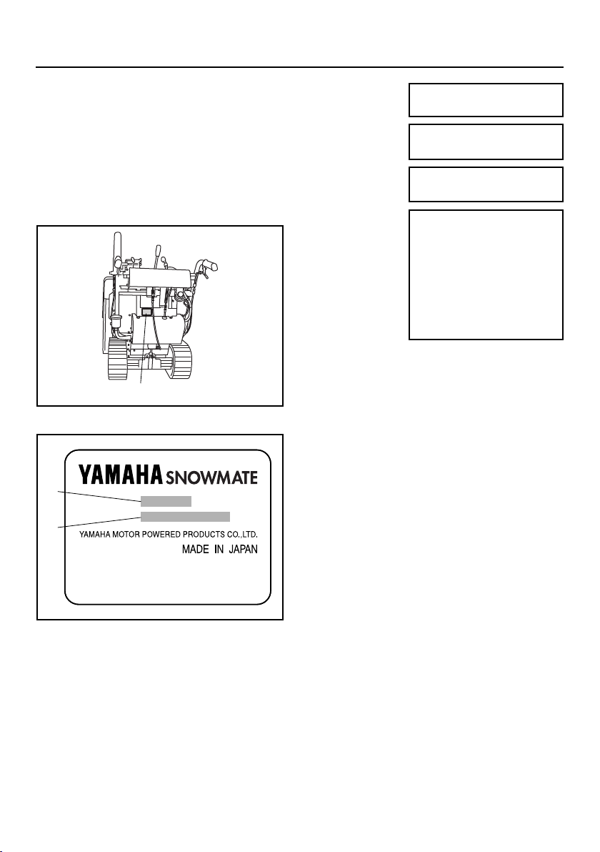
PRODUCT SERIAL NUMBER LABEL..... 1
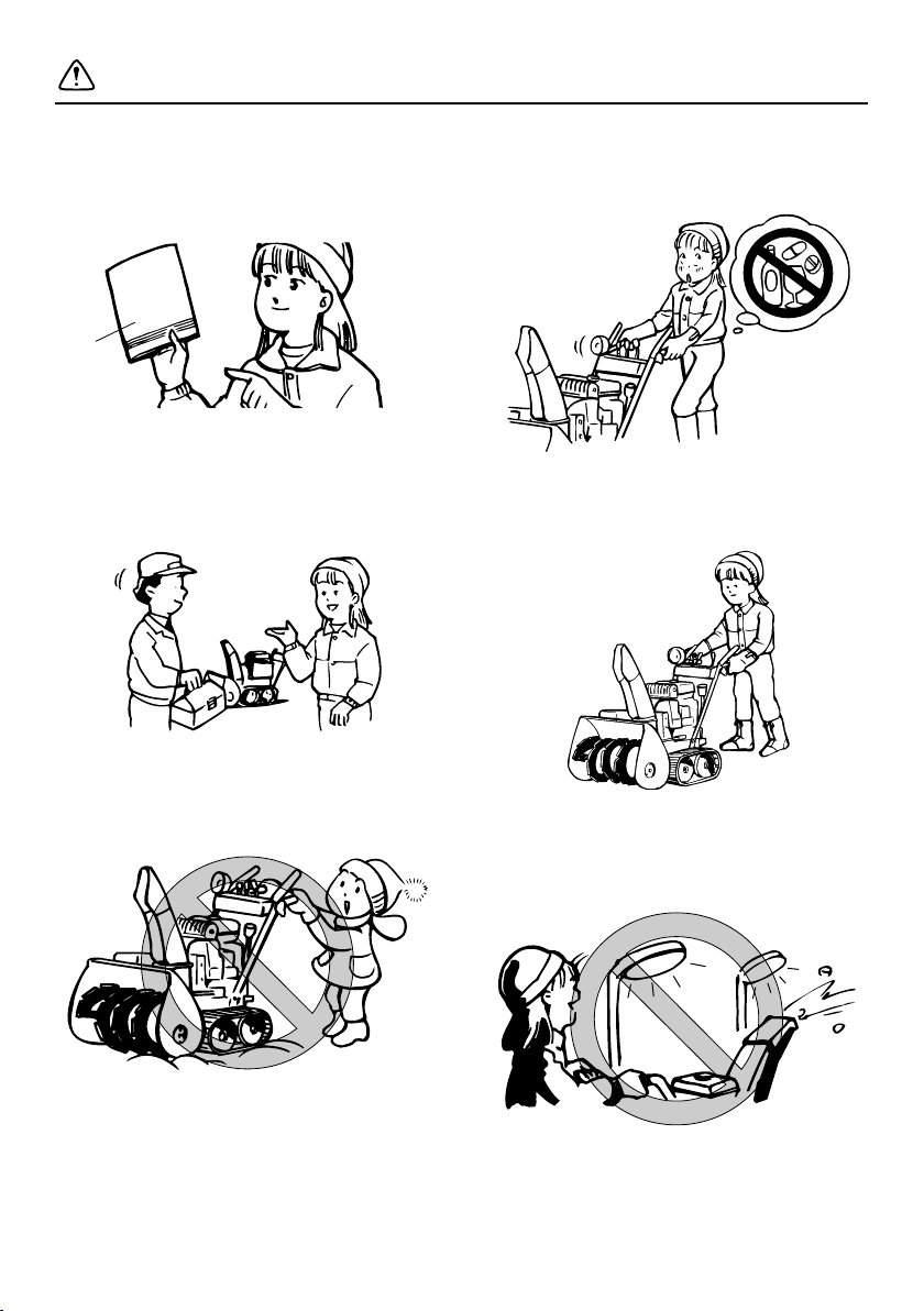
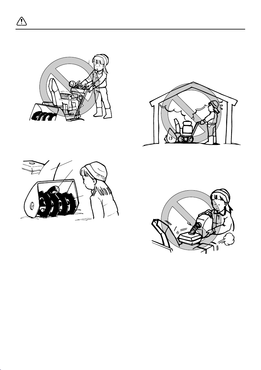
SAFETY INFORMATION .......................... 2
LOCATION OF IMPORTANT LABELS ....7
DESCRIPTION..........................................9
CONTROL FUNCTION ...........................14
ENGINE SWITCH................................14
OIL LEVEL WARNING LIGHT .............15
THROTTLE LEVER ............................. 15
SHIFT LEVER...................................... 16
CHUTE DIRECTION CONTROL
LEVER.............................................. 16
CHUTE DEFLECTOR CONTROL
LEVER.............................................. 17
DRIVE CLUTCH LEVER......................18
AUGER CLUTCH LEVER....................18
AUGER HOUSING HEIGHT
CONTROL LEVER ...........................19
FUEL TANK CAP .................................19
FUEL GAUGE......................................20
FUEL COCK ........................................ 20
FUSES.................................................21
SKID ....................................................21
SCRAPER ...........................................22
SHEAR BOLT GUARD.........................22
CLEAN-OUT TOOL
(LODGED SNOW REMOVER).........23
WORKING LIGHT................................24
PRE-OPERATION CHECK.....................25
CHECK BEFORE USE ........................25
CHECKING THE FUEL LEVEL ...........26
CHECKING THE ENGINE OIL ............27
CHECKING THE TRANSMISSION
(HST) OIL ......................................... 28
CHECKING THE AUGER ....................29
CHECKING THE HANDLEBAR FOR
LOOSENESS OR PLAY ...................29
CHECKING THE STARTER MOTOR
OPERATION..................................... 29
CHECKING THE ENGINE FOR
POOR STARTING OR ABNORMAL
NOISE .............................................. 29
CHECKING THE EXHAUST
SYSTEM .......................................... 29
CHECKING THE AUGER CLUTCH
AND DRIVE CLUTCH FOR
OPERATION MALFUNCTION ......... 29
CHECKING THE CHUTE
OPERATION .................................... 29
CHECKING ANY TROUBLES
NOTICED WHEN PREVIOUSLY
OPERATING THE
SNOWBLOWER............................... 29
OPERATION ........................................... 30
STARTING THE ENGINE .................... 30
STOPPING THE ENGINE ................... 32
MOVING THE SNOWBLOWER .......... 32
CLEARING SNOW .............................. 34
STOPPING CLEARING SNOW........... 37
MOVING THE SNOWBLOWER
WITH THE ENGINE STOPPED ....... 38
PERIODIC MAINTENANCE ................... 40
CHECK BEFORE USE........................ 40
PERIODIC INSPECTION .................... 40
MAINTENANCE CHART ..................... 41
CHANGING THE ENGINE OIL ........... 43
REFILLING THE TRANSMISSION
(HST) OIL......................................... 44
CHANGING THE WORM CASE
OIL ................................................... 46
CHECKING AND CLEANING THE
SPARK PLUG................................... 46
CLEANING THE FUEL STRAINER..... 48
ADJUSTING THE SKIDS .................... 50
REPLACING THE SHEAR BOLTS ...... 51
ADJUSTING THE SCRAPER.............. 52
CHECKING AND ADJUSTING THE
TRACK TENSION ............................ 53
REPLACING THE SPROCKET PIN .... 55
CONTENTS
7VY-9-70_E0.fm -1 ページ 2010年4月30日 金曜日 午前9時35分

CHECKING THE BATTERY FLUID .....56
REPLACING THE FUSE .....................57
LUBRICATING EACH PART ................ 58
STORAGE............................................... 59
SHORT-TERM......................................59
LONG-TERM .......................................63
SPECIFICATIONS ..................................64
INDEX .....................................................65
CONTENTS
7VY-9-70_E0.fm 0 ページ 2010年4月30日 金曜日 午前9時35分

– 1 –
Both the product name and the product
serial number are required when making
inquiries and reordering of parts.
Check the product serial number label, and
fill the product name and the serial number
columns at right.
Also, record the product name and product
serial number separately in case of theft or
emergency.
1. Product serial number label
1. Product name
2. Product serial number
1
1
2
Product name:
Product serial
number:
Date of
purchase:
Purchased
from:
Phone:
PRODUCT SERIAL NUMBER LABEL
7VY-9-70_E0.fm 1 ページ 2010年4月30日 金曜日 午前9時35分

– 2 –
Read and understand this owner’s manual
and labels attached to the Snowblower
completely before operating the Snow-
blower.
1. Owner’s manual
Be sure to perform the pre-operation
checks and periodic maintenance.
Do not allow children or anyone who does
not understand how to operate the Snow-
blower correctly to operate it.
Never operate the Snowblower when you
are tired or under the influence of alcohol or
drugs.
Wear non-slip footwear, warm clothing and
gloves when operating the Snowblower.
Do not operate the Snowblower in low visi-
bility conditions, such as early morning and
night time.
1
SAFETY INFORMATION
7VY-9-70_E0.fm 2 ページ 2010年4月30日 金曜日 午前9時35分

– 3 –
Do not start the engine with the guard or
cover removed.
Check for foreign objects in rotating parts
such as the auger and impeller or in the
chute before operating.
1. Auger
2. Impeller
3. Chute
Never start the engine indoors except when
you are moving the Snowblower.
Exhaust fumes contain harmful chemicals
such as carbon monoxide. Open the door
and adequately ventilate the building even
when you are moving the Snowblower.
Gasoline is a highly flammable and easily
ignitable fuel. Always turn off the engine
and avoid open flame while filling the fuel
tank.
3
2
1
!
S
SAFETY INFORMATION
7VY-9-70_E0.fm 3 ページ 2010年4月30日 金曜日 午前9時35分

– 4 –
Remove wooden blocks, cans, hoses,
wires, ropes and all other foreign objects
from the location you wish to clear snow
from before operating the Snowblower.
To clear snow on gravel, make sure there is
a clearance between the auger housing
and ground to prevent gravel from being
blown together with snow.
1. Auger housing
2. Clearance
Do not allow anyone except the operator of
the Snowblower near the place you wish to
clear snow from.
Do not look in the rotating parts such as the
auger and impeller or in the chute or put
your face, arms or legs near such parts.
1. Auger
2. Impeller
3. Chute
Do not blow snow toward people, buildings,
automobiles, etc.
Do not blow snow across the face of a
slope.
1
2
1
2
3
SAFETY INFORMATION
7VY-9-70_E0.fm 4 ページ 2010年4月30日 金曜日 午前9時35分

– 5 –
Do not use the Snowblower to clear snow
on a roof or steep slope.
If abnormal vibrations, noises or odors are
noticed coming from the Snowblower, stop
the engine and ask your Yamaha dealer to
check and/or perform maintenance.
When you park the Snowblower, stop it on a
flat surface and lower auger onto the
ground. Then, place shift lever in a position
other than “N” (Neutral).
1. Auger
2. Shift lever
The muffler (exhaust pipe) will still be hot
immediately after the engine has stopped.
Place the Snowblower in a place where
pedestrians are not likely to touch the
Snowblower.
1
2
SAFETY INFORMATION
7VY-9-70_E0.fm 5 ページ 2010年4月30日 金曜日 午前9時35分

– 6 –
Do not use the Snowblower for purposes
other than clearing snow.
To dislodge snow from the chute, stop the
engine, and use the clean-out tool.
1. Chute
To attach a cover or similar device to the
Snowblower, wait until the engine and muf-
fler have completely cooled down.
1
SAFETY INFORMATION
7VY-9-70_E0.fm 6 ページ 2010年4月30日 金曜日 午前9時35分

– 7 –
12 345
6 7
To use the product safely, read the labels affixed to the machine, and use according to the
instructions on the labels.
TIP
If these important labels are damaged or missing, contact your Yamaha dealer for replace-
ments.
LOCATION OF IMPORTANT LABELS
21
7VY-9-70_E0.fm 7 ページ 2010年4月30日 金曜日 午前9時35分

– 8 –
LOCATION OF IMPORTANT LABELS
3 4
5
7VY-2179R-00
6 7
7VY-9-70_E0.fm 8 ページ 2010年4月30日 金曜日 午前9時35分

– 9 –
DESCRIPTION
1. Chute
2. Battery cover/Battery
3. Transmission (HST) oil reservoir
4. Muffler
5. Fuel cock
6. Left side cover
7. Track
8. Auger
9. Impeller
10. Auger housing
11. Clean-out tool (lodged snow remover)
12. Side marker (snow slicer)
8
9
10
11
12
1
2
3
4
5
6
7
7VY-9-70_E0.fm 9 ページ 2010年4月30日 金曜日 午前9時35分

– 10 –
1. Working light
2. Right side cover
3. Engine oil inspection cover
4. Scraper
5. Skid
6. Control panel
7. Handlebar
77
6
5
4
3
2
1
DESCRIPTION
7VY-9-70_E0.fm 10 ページ 2010年4月30日 金曜日 午前9時35分

– 11 –
1. Drive clutch lever
2. Auger clutch lever
3. Shift lever
4. Chute direction control lever
5. Chute deflector control lever
6. Throttle lever
7. Oil level warning light
8. Auger housing height control lever
9. Engine switch
1. Fuel cock lever
2. “RUN”
3. “STOP”
4. Fuel cock
5. “CARBURETOR DRAIN”
6. “HOSE DRAIN”
1. Fuel gauge
2. Fuel tank cap
3. Fuel tank
7
5
4
1
2
3
6
98
RUN
S
T
O
P
H
O
S
E
CARBURETOR
D
R
A
I
N
1
4
2
5
63
13
2
DESCRIPTION
7VY-9-70_E0.fm 11 ページ 2010年4月30日 金曜日 午前9時35分

– 12 –
1. Fuse
2. Electric starter
3. Engine oil filler cap
4. Engine oil drain bolt
21
43
DESCRIPTION
7VY-9-70_E0.fm 12 ページ 2010年4月30日 金曜日 午前9時35分

– 13 –
1. Spark plug cap/Spark plug
2. Carburetor
3. Air filter
4. Fuel drain hose
5. Fuel strainer cup
6. Fuel cock lever
123
4
56
DESCRIPTION
7VY-9-70_E0.fm 13 ページ 2010年4月30日 金曜日 午前9時35分

– 14 –
CONTROL FUNCTION
ENGINE SWITCH
1. “STOP ”
2. “ON ”
3. “START ”
4. Grip
The engine switch controls the ignition and
the starter motor system.
STOP :
Position to stop the engine.
The key can be inserted or removed.
ON :
Position when the engine is running.
The key cannot be removed.
START :
Position to start the engine.
The starter motor cranks the engine. When
releasing the grip, the key returns to the
“ON ” position automatically.
The key cannot be removed.
NOTICE
• Do not continue to use the starter
motor for more than 5 seconds.
Doing so will consume a large
amount of power and it may exhaust
the battery.
• Do not leave the key in the “ON ”
position for a long time while the
engine is stopped. It may exhaust
the battery.
TIP
Remove the engine switch key when you
are not using the Snowblower.
1
23
4
7VY-9-70_E0.fm 14 ページ 2010年4月30日 金曜日 午前9時35分

– 15 –
OIL LEVEL WARNING LIGHT
1. Oil level warning light
The oil level warning light comes on when
the engine oil level falls below the specified
limit during operation.
If the oil level warning light comes on, stop
the engine immediately, and add engine oil
up to the specified level.
TIP
The oil level warning light may come on
when the Snowblower is tilted excessively.
If so, park the Snowblower on a level sur-
face and check if the oil level warning light
comes on.
THROTTLE LEVER
1. Throttle lever
2. “FAST (START) ”
3. “SLOW ”
Controls the engine speed.
FAST (START) :
Lever position to start the engine and to
start snow clearing or moving.
SLOW :
Lever position to idle the engine.
1
2
13
CONTROL FUNCTION
7VY-9-70_E0.fm 15 ページ 2010年4月30日 金曜日 午前9時35分

– 16 –
SHIFT LEVER
1. Shift lever
2. “F” (Forward)
3. “N” (Neutral)
4. “R” (Reverse)
Used to switch to forward or reverse move-
ment, and to control traveling speed.
NOTICE
Slowly move the shift lever from the “N”
(Neutral) position to the desired position
appropriate to your operation.
CHUTE DIRECTION
CONTROL LEVER
1. Chute direction control lever
2. Right
3. Left
4. Chute
5. Clockwise
6. Counterclockwise
Used to change the direction that snow is
blown.
Move the chute direction control lever to
the right:
The chute rotates clockwise.
Move the chute direction control lever to
the left:
The chute rotates counterclockwise.
NOTICE
• Do not press the chute direction
control lever forcefully. Doing so
may damage the switch.
• When the chute is locked, do not
continue to press the chute direc-
tion control lever.
If you do so, the motor breaker may
trip or the motor may be damaged.
• Use the chute direction control lever
when the engine is running.
1
2
3
4
2
3
5
4
1
6
CONTROL FUNCTION
7VY-9-70_E0.fm 16 ページ 2010年4月30日 金曜日 午前9時35分
Table of contents
Other Yamaha Snow Blower manuals