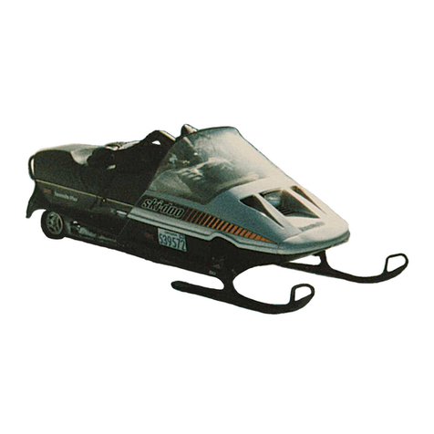
Yamaha Phazer Venture Lite PZ50MTA 2011 Manual


FOREWORD
This Supplementary Service Manual has been prepared to introduce new service and new data for
the PZ50GTA, PZ50RTA, PZ50MTA, PZ50VTA. For complete information, on service procedures, it
is necessary to use this Supplementary Service Manual together with following manual:
PZ50W, PZ50GTW, PZ50FXW, PZ50MW, PZ50VTW, PZ50MPW SERVICE MANUAL:
8GC-28197-10 (LIT-12618-02-58)
PZ50X, PZ50GTX, PZ50RTX, PZ50MTX, PZ50VTX, PZ50MPX
SUPPLEMENTARY SERVICE MANUAL:
8GC-28197-11 (LIT-12618-02-67)
PZ50GTA, PZ50RTA, PZ50MTA, PZ50VTA
SUPPLEMENTARY SERVICE MANUAL
©2010 by Yamaha Motor
Corporation, U.S.A.
1st Edition, April 2010
All rights reserved. Any reprinting or
unauthorized use without the written
permission of Yamaha Motor Corporation,
U.S.A. is expressly prohibited.
Printed in U.S.A.
P/N.LIT-12618-02-93

MAJOR SPECIFICATIONS
Model PZ50GTA PZ50RTA PZ50MTA PZ50VTA
Model code 8GK7 8GN9 8GP9 8GJ9
Catalogue name Phazer GT Phazer RTX Phazer MTX Venture Lite
Class Trail Mountain 2-Up Touring
Utility
Seating capacity One Two
Engine type Liquid cooled 4-stroke, 10valves
Cylinder arrangement/
Displacement Backward-inclined parallel 2-cylinder/499cm3
Fuel system type Electronic fuel injection
Track length 3,072.4 mm (121 in) 3,648.5 mm (144 in)
Front suspension Independent, double wishbone
Front shock
absorber
40 mm GYTR®
dual-clicker HPG
Fox®FLOATTM
(air shock) KYB®gas cell KYB®gas cell
Rear suspension Dual Shock®Dual Shock®CK ProMountain®144 ProComfort®144
Rear shock
absorber
Front C36 KYB®HPG C36 KYB®
aluminum HPG C36 KYB®HPG KYB®gas cell
Rear C36 KYB®HPG C40 aluminum HPG C36 KYB®HPG KYB®gas cell
Ski type Lightweight plastic, saddleless design Wide saddleless
plastic mountain ski
Lightweight
plastic, saddleless
design
Electric start Standard
Reverse Standard

IMPORTANT
This manual was produced by the Yamaha Motor Company, Ltd. primarily for use by Yamaha deal-
ers and their qualified mechanics. It is not possible to include all the knowledge of a mechanic in one
manual. Therefore, anyone who uses this book to perform maintenance and repairs on Yamaha
snowmobiles should have a basic understanding of mechanics and the techniques to repair these
types of snowmobiles. Repair and maintenance work attempted by anyone without this knowledge
is likely to render the snowmobile unsafe and unfit for use.
This model has been designed and manufactured to perform within certain specifications in regard
to performance and emissions. Proper service with the correct tools is necessary to ensure that the
snowmobile will operate as designed. If there is any question about a service procedure, it is imper-
ative that you contact a Yamaha dealer for any service information changes that apply to this model.
This policy is intended to provide the customer with the most satisfaction from his snowmobile and
to conform to federal environmental quality objectives.
Yamaha Motor Company, Ltd. is continually striving to improve all of its models. Modifications and
significant changes in specifications or procedures will be forwarded to all authorized Yamaha deal-
ers and will appear in future editions of this manual where applicable.
TIP
• This Service Manual contains information regarding periodic maintenance to the emission control
system.
Please read this material carefully.
• Designs and specifications are subject to change without notice.
IMPORTANT MANUAL INFORMATION
Particularly important information is distinguished in this manual by the following notations.
This is the safety alert symbol. It is used to alert you to potential per-
sonal injury hazards. Obey all safety messages that follow this symbol
to avoid possible injury or death.
A WARNING indicates a hazardous situation which, if not avoided,
could result in death or serious injury.
WARNING
A NOTICE indicates special precautions that must be taken to avoid
damage to the snowmobile or other property.
NOTICE
A TIP provides key information to make procedures easier or clearer.
TIP

ILLUSTRATED SYMBOLS
(Refer to the illustration)
Illustrated symbols to are designed as
thumb tabs to indicate the chapter’s number
and content.
General information
Periodic inspection and adjustment
Chassis
Power train
Engine
Cooling system
Fuel injection system
Electrical
Specifications
Illustrated symbols to are used to iden-
tify the specifications which appear.
Filling fluid
Lubricant
Tightening torque
Wear limit, clearance
Engine speed
Special tool
Electrical data (Ω, V, A)
Illustrated symbols to in the exploded
diagram indicate grade of lubricant and loca-
tion of lubrication point.
Apply locking agent (LOCTITE®)
Apply Yamabond No. 5®
Apply engine oil
Apply gear oil
Apply molybdenum disulfide oil
Apply brake fluid
Apply wheel bearing grease
Apply low-temperature lithium-soap-based
grease
Apply molybdenum disulfide grease
Apply silicone grease
ESSO beacon 325 grease or Aeroshell
grease #7A
Use new one

CONTENTS
GENERAL INFORMATION GEN
INFO 1
PERIODIC INSPECTION AND
ADJUSTMENT INSP
ADJ 2
CHASSIS CHAS 3
POWER TRAIN POWR
TR 4
ENGINE ENG 5
COOLING SYSTEM COOL 6
FUEL INJECTION SYSTEM FI 7
ELECTRICAL ELEC 8
SPECIFICATIONS SPEC 9


CHAPTER 1.
GENERAL INFORMATION
FEATURES.................................................... 1
OIL PRESSURE SENSING SYSTEM ......1
CHAPTER 2.
PERIODIC INSPECTION AND
ADJUSTMENT
ENGINE .........................................................2
ENGINE OIL REPLACEMENT .................2
CHAPTER 5.
ENGINE
OIL PAN AND OIL PUMP ............................. 6
CHAPTER 7.
FUEL INJECTION SYSTEM
FUEL INJECTION SYSTEM..........................8
WIRING DIAGRAM (PZ50GTA,
PZ50RTA, PZ50MTA)...............................9
WIRING DIAGRAM (PZ50VTA)..............11
ECU SELF-DIAGNOSTIC FUNCTION ...13
SELF-DIAGNOSTIC FUNCTION
TABLE.....................................................13
TROUBLESHOOTING CHART ..............15
DIAGNOSTIC MODE.............................. 16
OIL PRESSURE SENSING SYSTEM
TROUBLESHOOTING ............................ 26
OIL PRESSURE SENSOR .....................27
CHAPTER 8.
ELECTRICAL
SWITCH INSPECTION ............................... 28
SWITCH INSPECTION .......................... 28
INSPECTING A SWITCH SHOWN IN
THE MANUAL ........................................ 29
CHAPTER 9.
SPECIFICATIONS
GENERAL SPECIFICATIONS.................... 30
MAINTENANCE SPECIFICATIONS ........... 30
FRONT SUSPENSION........................... 30
POWER TRAIN ...................................... 30
ELECTRICAL ......................................... 31
TIGHTENING TORQUE .............................. 31
ENGINE.................................................. 31
CABLE ROUTING....................................... 32

GEN
INFO
1
GENERAL INFORMATION
FEATURES
OIL PRESSURE SENSING SYSTEM
This model is equipped with an oil pressure sensing system. When the oil pressure drops, the rpm
limiter is activated, and the engine rpm is reduced, or the engine is shut off, if necessary.
If the oil pressure is incorrect upon starting the engine
1. “OP-LO” appears and the oil level/pressure warning indicator illuminates on the meter dis-
play.
2. When the two items, above, are displayed, they indicate the rpm limiter is in operation; the rpm is
reduced to less than or equal to the clutch engagement rpm, even though the throttle is open. If
the incorrect oil pressure persists, the engine stops automatically after approximately one
minute.
3. When the oil pressure stabilizes to the correct level (“OP-LO” disappears and the oil level/pres-
sure warning indicator goes off), the limiter is automatically canceled as long as the throttle is not
operated.
4. Note that it may take a few seconds for the oil pressure to rise to the optimum level after the
engine is started, even in normal conditions. If the meter display described in (1) is no longer dis-
played after a few seconds, this indicates that everything is normal.
TIP
When disassembling the engine, replacing the engine oil or oil filter, etc., if the oil is drained entirely
from the piping, there may be delay before the oil pressure rises.
If abnormally low oil pressure is detected when the snowmobile is running
1. Fault code No. 30 appears on the meter display.
2. If the snowmobile runs at high speed simultaneously, the engine rpm decreases gradually and
the engine is shut off, after approximately seven seconds. If the snowmobile runs at low speed,
the engine is shut off immediately.
If air has entered the oil pressure line due to excessive snowmobile movement (falling over, exces-
sive tilting, etc.), the oil pressure may drop and the system may be activated.
Refer to “OIL PRESSURE SENSING SYSTEM TROUBLESHOOTING”.
FEATURES

INSP
ADJ
2
PERIODIC INSPECTION AND
ADJUSTMENT
ENGINE
ENGINE OIL REPLACEMENT
This model is equipped with an oil pressure
sensing system. When the oil pressure drops,
the rev limiter is activated, and the engine is
stopped, if necessary. If the oil pressure is
incorrect when the engine is started, “OP-LO”
appears and the oil level/pressure warning
indicator illuminates. Note that it may take a
few seconds for the oil pressure to rise to the
optimum level after the engine is started, even
in normal conditions.
Refer to “OIL PRESSURE SENSING SYS-
TEM”.
TIP
If “OP-LO” remains on and the oil level/pres-
sure warning indicator remains illuminated for
more than a few seconds after starting the
engine, this indicates that oil pressure is incor-
rect. In this case, check the oil pressure sens-
ing system.
1. Place the snowmobile on a level surface
and apply the parking brake.
2. Start the engine, warm up for several min-
utes, and then turn it off.
3. Place a containers under the engine oil
drain bolt and oil tank.
4. Remove:
• Bottom panel
5. Remove:
• Left side panel
• Right side cover
• Right lower cover
Refer to “COWLINGS” in CHAPTER 3.
6. Disconnect:
• Oil level gauge coupler
Refer to “ENGINE OIL LEVEL INSPEC-
TION” in CHAPTER 2.
7. Remove:
• Oil level gauge/dipstick
Refer to “ENGINE OIL LEVEL INSPEC-
TION” in CHAPTER 2.
ENGINE OIL REPLACEMENT

INSP
ADJ
3
8. Remove:
• Cylinder head oil filler cap
9. Remove:
• Oil pan engine oil drain bolt
10.Remove:
• Oil tank engine oil drain bolt
11.Drain:
• Engine oil
(completely from the oil pan and oil tank)
12.If the oil filter cartridge is also to be
replaced, perform the following procedure.
Replacement steps:
• Remove the air filter case.
Refer to “COWLINGS” in CHAPTER 3.
• Remove the oil cooler bolts .
• Remove the oil cooler.
• Remove the oil filter cartridge with an oil
filter wrench .
Oil filter wrench:
90890-01469, YM-01469
ENGINE OIL REPLACEMENT

INSP
ADJ
4
• Apply a thin coat of engine oil onto the O-
ring of the new oil filter cartridge.
NOTICE
Make sure that the O-ring is positioned
correctly in the groove of the oil filter car-
tridge.
• Tighten the new oil filter cartridge to specifi-
cation with an oil filter wrench.
• Tighten the oil cooler bolts to specification.
13.Install:
• Drain bolts
(along with the new gaskets)
14.Fill:
• Engine oil
(with the specified amount of the recom-
mended engine oil)
Add 1.5 L (1.3 Imp.qt, 1.6 US qt) of the rec-
ommended engine oil to the oil tank, and
then install and tighten the oil level gauge/
dipstick and the cylinder head cap.
Oil filter cartridge:
17 Nm (1.7 m•kgf, 12 ft•lbf)
Oil cooler bolt:
10 Nm (1.0 m•kgf, 7.2 ft•lbf)
LOCTITE®
Oil tank engine oil drain bolt:
16 Nm (1.6 m•kgf, 12 ft•lbf)
Oil pan engine oil drain bolt:
30 Nm (3.0 m•kgf, 22 ft•lbf)
Quantity:
Total amount:
3.00 L (2.64 Imp.qt,
3.17 US qt)
Periodic oil change:
2.45 L (2.16 Imp.qt,
2.59 US qt)
With oil filter replacement:
2.63 L (2.31 Imp.qt,
2.78 US qt)
ENGINE OIL REPLACEMENT

INSP
ADJ
5
15.Inspect:
• Engine and oil tank
(for engine oil leaks)
16.Inspect:
• Engine oil level
Refer to “ENGINE OIL LEVEL INSPEC-
TION” in CHAPTER 2.
TIP
If “OP-LO” remains on and the oil level/pres-
sure warning indicator remains illuminated for
more than a few seconds after starting the
engine, this indicates that oil pressure is incor-
rect. In this case, check the oil pressure sens-
ing system.
Refer to “OIL PRESSURE SENSING SYSTEM
TROUBLESHOOTING”.
17.Inspect:
• Engine oil pressure
Inspection steps:
• Remove the exhaust pipe joint upper cover.
Refer to “EXHAUST PIPE AND MUFFLER”
in CHAPTER 5.
• Slightly loosen the oil gallery bolt .
• Install the fuel tank.
Refer to “SEAT AND FUEL TANK” in
CHAPTER 5.
Refer to “RIDER SEAT AND FUEL TANK”
in CHAPTER 5.
• Start the engine and keep it idling until
engine oil starts to seep from the oil check
bolt.
If no engine oil comes out after one minute,
turn the engine off so that it will not seize.
• Check the engine oil passages, the oil filter
and the oil pump for damage or leakage.
• Start the engine after solving the problem(-s)
and check the engine oil pressure again.
• Tighten the oil check bolt to specification.
Oil check bolt:
10 Nm (1.0 m•kgf, 7.2 ft•lbf)
ENGINE OIL REPLACEMENT

ENG
6
ENGINE
OIL PAN AND OIL PUMP
Order Job name/Part name Q’ty Remarks
Oil pan and oil pump removal Remove the parts in the order listed below.
Engine Refer to “ENGINE ASSEMBLY”.
Starter clutch gear Refer to “A.C. MAGNETO ROTOR AND
STARTER CLUTCH”.
1 Oil tank inlet hose 1
2 Oil tank outlet hose 1
3 Oil pressure switch 1
4 Oil pressure sensor 1
5 Oil filter cartridge 1
6 Oil pan 1
7Gasket 1
8 Dowel pin 2
9 Oil pump drive chain guide 1
10 Oil pump driven sprocket shaft 1
11 Oil pump driven sprocket 1
12 Oil pump drive chain 1
13 Oil pump 1
OIL PAN AND OIL PUMP

ENG
7
Order Job name/Part name Q’ty Remarks
14 Dowel pin 2
15 Collar 2
16 O-ring 2
17 Gasket 1
OIL PAN AND OIL PUMP

FI
8
FUEL INJECTION SYSTEM
Battery
ECU (engine control
unit)
Fuel injection system
relay
Cylinder-#2 ignition
coil
Spark plug
Fuel pump
Cylinder identification
sensor
Cylinder-#1 ignition
coil
Cylinder-#1 intake air
pressure sensor
Speed sensor
Throttle position sen-
sor
Injector #1
Oil pressure sensor
Knock sensor
Oil pressure switch
Coolant temperature
sensor
Crankshaft position
sensor
Injector #2
Cylinder-#2 intake air
pressure sensor
Intake air temperature
sensor
Grip/thumb warmer
adjustment switch
Warning light
FUEL INJECTION SYSTEM

FI
9
WIRING DIAGRAM (PZ50GTA, PZ50RTA, PZ50MTA)
FUEL INJECTION SYSTEM

FI
10
Crankshaft position sensor
Main switch
Main fuse
Load control relay
Fuel injection system fuse
Battery
Engine stop switch
Throttle switch
Oil pressure sensor
Grip warmer
Thumb warmer
Oil pressure switch
Drive position switch
Reverse position switch
ECU (engine control unit)
Cylinder-#1 ignition coil
Spark plug
Cylinder-#2 ignition coil
Injector #1
Injector #2
Fuel injection system relay
Fuel pump
Throttle position sensor
Speed sensor
Cylinder identification sensor
Cylinder-#1 intake air pressure sensor
Cylinder-#2 intake air pressure sensor
Knock sensor
Coolant temperature sensor
Intake air temperature sensor
Grip/thumb warmer adjustment switch
Speedometer unit
Multi-function meter
Warning light
Headlight
Headlight relay
Headlight beam switch
Radiator fan motor
Radiator fan motor relay
Ignition fuse
Radiator fan motor fuse
Headlight fuse
FUEL INJECTION SYSTEM

FI
11
WIRING DIAGRAM (PZ50VTA)
FUEL INJECTION SYSTEM
This manual suits for next models
3
Table of contents
Other Yamaha Snowmobile manuals

Yamaha
Yamaha VX500C User manual

Yamaha
Yamaha FX Nytro FX10X User manual

Yamaha
Yamaha PZ50W User manual

Yamaha
Yamaha APEX RX10RY User manual

Yamaha
Yamaha SR1NLK User manual

Yamaha
Yamaha PZ500C User manual

Yamaha
Yamaha FX Nytro FX10A User manual

Yamaha
Yamaha SXV4NP User manual

Yamaha
Yamaha SXV70SJ Manual

Yamaha
Yamaha SnoScoot SXR2NJ User manual
Yamaha
Yamaha RX10K User manual

Yamaha
Yamaha RX10RTL User manual

Yamaha
Yamaha VK540EF User manual

Yamaha
Yamaha VENTURE PZ5NXJ User manual

Yamaha
Yamaha FX Nytro FX10X User manual

Yamaha
Yamaha PZ50FXW User manual

Yamaha
Yamaha EC340E Manual

Yamaha
Yamaha RX10RTW Manual

Yamaha
Yamaha RS Venture RST90Y User manual

Yamaha
Yamaha VT600C User manual