CONTROLS
AND
FUNCTIONS
00000
00000
00000 00000
00000
00000
00000
00000 00000
00000
00000
00000
00000
00000 00000
00000
00000
00000
00000
00000 00000
00000
00000
00000
00000
00000 00000
00000 00000 00000
00000 00000
00000
00000 00000
00000
00000 00000
00000 00000
00000
00000
CD®
@
~
® ®
(])
®
~
It
~
1
!.:
,I:,,'..
~~j
,
z;'''';'
~
0/
~
'I
II
_....:t,..-J~:
------.i/_-----------:~"...:
----......an~-----__;~~
il"",."""iI·"""'''''''''h
~
11""""",,,,,,,,,,,,,,,,,,,,,,,,,,,,,,,,,,,,,,,,,,,,,,,,,,,,,,,,,,,,,,,,,,,,,,,,,,,,,,,,,,,,,,11"''''''''''",,,,,"',,,,,,,,,,,,,,,,"',,,,,,"',,,,,,,,,,,,,,,,,,,,,,,,,,,,,,"',,,,,,,,,,,,,"',,,,,,,,,,,,,,,,,,,
"'"''''''''''''''''''''''''''''''''''''''''''''''''''''''''''''''''''''1.'''''''''''''''''''''''''''''''''"""""""""Ift"",,,,,,,,,,,,,,,,,,,,,",,,,,,,,,,,,,,,",,,,",,,,,,,,,,,,,,,,,,,,,,,,,",,,,,;q,,
,,,,,,,,,,,,,,,,,,,,,,,,,,,,,,,,,,,,,,,,,,,,,,,,,,,,,,,,,,,,",,,,,,,,,,,,,,,,,,,,,,,,,11"""'"'''""""""''''''''''''''''''''''11
1
~!t>DVD
I>DTV/CBL
I>VCR
I>MD/TAPE!
I>CD
~
I>TUNER !I>PHONO
~I>XM
z
t~"",,",~j
h""ZONE2
MEMORY
AUTO TUNED STEREO
SLEEP,,,.7J
DI
\nll-
...
~,"'il
00000
00000 00000 00000
00000
~
00000
00000
00000
j"PTy""'H'6"L'o"i
00000
00000 00000
00000 00000
t
00000
00000
00000
1EON
~
00000
00000 00000 00000
88888
~
88888
00000
88888
~
l
88888
88888 88888
88888
00000
~
00000
88888
00000
z0PS 0PTY z
88888
88888 88888
88888
88888!
88888 88888
88888
~
0RT 0CT
~
II"""",,,,,,,,,,,,,,,,,,,,,,,,,,,,,,,,,,,,,,,,,,,,,,,,,,,,,,,,,,,,,,,,,,,,,,,,,,,,,,,,,,,,,.,,,,,,,,
","''''''''''''''''''','''''''''''''''''''''''''''''''''',''''''''''''''''''",''''''',''''''''',''''''"""'"''''''''~'''''''''''''.''''''''''''''''''''''''''''''''','''''''''''''''''''''''''''''.'''''''''''''
"""""''''''''''''''''''''''''''''''''''''''''''''''''''''''''''''''''''''''''''''''''''''''''''ifi'''''
"""',"'""""""""",.","""""",,,,,"',,,,,"',,,,,,,,,,,,,,,,,,,,,"',,,,,,,",,,,,,,/;'
rl"""""""""""",,,,,,,,m""ff,,,,,,,,,,,,,,,,,,,,,,,,,,,,,,,,,,,,11
y
CD
SP (SPEAKERS) AlB indicators
Light up according to the set
of
speakers selected.
Both indicators light up when both sets
of
speakers are
selected.
®ZONE 2indicator
Lights up when Zone 2is turned on.
@Input source indicators
Light up when this unit is in the
correspondi~g
mode.
The XM indicator
is
only applicable to the U.S.A. model.
@MEMORY indicator
Flashes for approximately 5seconds after MEMORY on
the front panel is pressed. While the MEMORY indicator
is
flashing, store the displayed station in the system
memory by using AIBICIDIE and one
of
the preset station
number buttons on the front panel.
®AUTO indicator
Lights up when this unit
is
in the automatic tuning mode.
®STEREO indicator
Lights up when this unit is receiving astrong signal for an
FM stereo broadcast while the AUTO indicator
is
lit.
(J)
SLEEP indicator
Lights up when the sleep timer is turned on.
®MUTE indicator
Flashes while the MUTE function is turned on.
®Multi-information display
Shows information when adjusting or changing settings.
®TUNED indicator
Lights up when this unit is tuned into astation.
•Europe model 'only
®Radio Data System indicators
The box-shaped indicator beside the name
of
each Radio
Data System mode lights up when the corresponding
Radio Data System mode is selected.
PTY HOLD indicator
Lights up while searching for stations in the PTY
SEEK mode.
EON indicator
Lights up when the Radio Data System station that
offers the EON data service is being received.
5
CONTROLS
AND
FUNCTIONS
00000
00000
00000 00000
00000
00000
00000
00000 00000
00000
00000
00000
00000
00000 00000
00000
00000
00000
00000
00000 00000
00000
00000
00000
00000
00000 00000
00000 00000 00000
00000 00000
00000
00000 00000
00000
00000 00000
00000 00000
00000
00000
CD®
@
~
® ®
(])
®
~
It
~
1
!.:
,I:,,'..
~~j
,
z;'''';'
~
0/
~
'I
II
_....:t,..-J~:
------.i/_-----------:~"...:
----......an~-----__;~~
il"",."""iI·"""'''''''''h
~
11""""",,,,,,,,,,,,,,,,,,,,,,,,,,,,,,,,,,,,,,,,,,,,,,,,,,,,,,,,,,,,,,,,,,,,,,,,,,,,,,,,,,,,,,11"''''''''''",,,,,"',,,,,,,,,,,,,,,,"',,,,,,"',,,,,,,,,,,,,,,,,,,,,,,,,,,,,,"',,,,,,,,,,,,,"',,,,,,,,,,,,,,,,,,,
"'"''''''''''''''''''''''''''''''''''''''''''''''''''''''''''''''''''''1.'''''''''''''''''''''''''''''''''"""""""""Ift"",,,,,,,,,,,,,,,,,,,,,",,,,,,,,,,,,,,,",,,,",,,,,,,,,,,,,,,,,,,,,,,,,",,,,,;q,,
,,,,,,,,,,,,,,,,,,,,,,,,,,,,,,,,,,,,,,,,,,,,,,,,,,,,,,,,,,,,",,,,,,,,,,,,,,,,,,,,,,,,,11"""'"'''""""""''''''''''''''''''''''11
1
~!t>DVD
I>DTV/CBL
I>VCR
I>MD/TAPE!
I>CD
~
I>TUNER !I>PHONO
~I>XM
z
t~"",,",~j
h""ZONE2
MEMORY
AUTO TUNED STEREO
SLEEP,,,.7J
DI
\nll-
...
~,"'il
00000
00000 00000 00000
00000
~
00000
00000
00000
j"PTy""'H'6"L'o"i
00000
00000 00000
00000 00000
t
00000
00000
00000
1EON
~
00000
00000 00000 00000
88888
~
88888
00000
88888
~
l
88888
88888 88888
88888
00000
~
00000
88888
00000
z0PS 0PTY z
88888
88888 88888
88888
88888!
88888 88888
88888
~
0RT 0CT
~
II"""",,,,,,,,,,,,,,,,,,,,,,,,,,,,,,,,,,,,,,,,,,,,,,,,,,,,,,,,,,,,,,,,,,,,,,,,,,,,,,,,,,,,,.,,,,,,,,
","''''''''''''''''''','''''''''''''''''''''''''''''''''',''''''''''''''''''",''''''',''''''''',''''''"""'"''''''''~'''''''''''''.''''''''''''''''''''''''''''''''','''''''''''''''''''''''''''''.'''''''''''''
"""""''''''''''''''''''''''''''''''''''''''''''''''''''''''''''''''''''''''''''''''''''''''''''ifi'''''
"""',"'""""""""",.","""""",,,,,"',,,,,"',,,,,,,,,,,,,,,,,,,,,"',,,,,,,",,,,,,,/;'
rl"""""""""""",,,,,,,,m""ff,,,,,,,,,,,,,,,,,,,,,,,,,,,,,,,,,,,,11
y
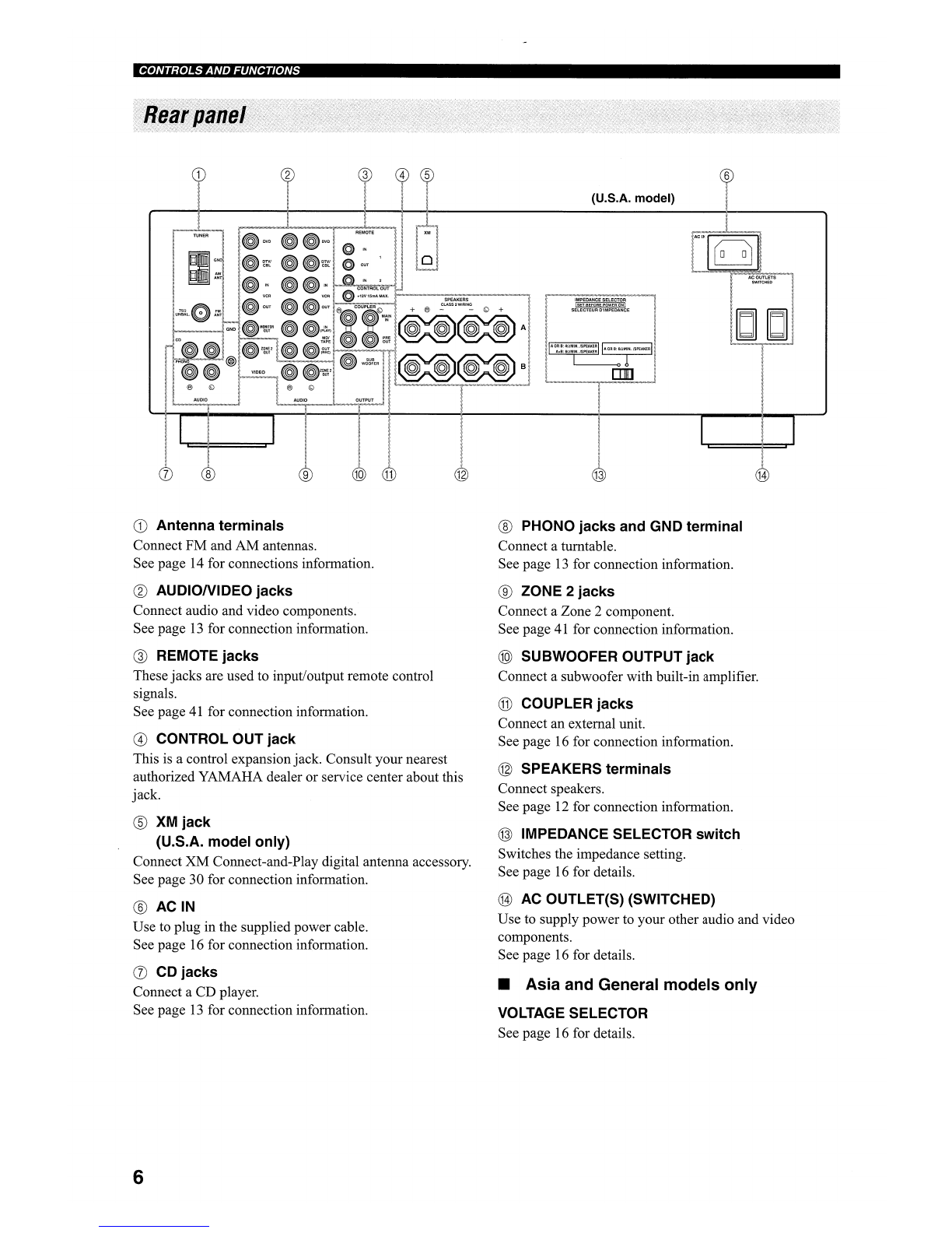
CD
SP (SPEAKERS) AlB indicators
Light up according to the set
of
speakers selected.
Both indicators light up when both sets
of
speakers are
selected.
®ZONE 2indicator
Lights up when Zone 2is turned on.
@Input source indicators
Light up when this unit is in the
correspondi~g
mode.
The XM indicator
is
only applicable to the U.S.A. model.
@MEMORY indicator
Flashes for approximately 5seconds after MEMORY on
the front panel is pressed. While the MEMORY indicator
is
flashing, store the displayed station in the system
memory by using AIBICIDIE and one
of
the preset station
number buttons on the front panel.
®AUTO indicator
Lights up when this unit
is
in the automatic tuning mode.
®STEREO indicator
Lights up when this unit is receiving astrong signal for an
FM stereo broadcast while the AUTO indicator
is
lit.
(J)
SLEEP indicator
Lights up when the sleep timer is turned on.
®MUTE indicator
Flashes while the MUTE function is turned on.
®Multi-information display
Shows information when adjusting or changing settings.
®TUNED indicator
Lights up when this unit is tuned into astation.
•Europe model 'only
®Radio Data System indicators
The box-shaped indicator beside the name
of
each Radio
Data System mode lights up when the corresponding
Radio Data System mode is selected.
PTY HOLD indicator
Lights up while searching for stations in the PTY
SEEK mode.
EON indicator
Lights up when the Radio Data System station that
offers the EON data service is being received.
5