Yamaha GX-500 User manual

GX-500/GX-500VCD
GX-500/VCD
100672
SERVICE MANUAL
GX-500
GX-500VCD
MINI COMPONENT SYSTEM
IMPORTANT NOTICE
This manual has been provided for the use of authorized YAMAHA Retailers and their service personnel.
It has been assumed that basic service procedures inherent to the industry, and more specifically YAMAHA Products, are
already known and understood by the users, and have therefore not been restated.
WARNING: Failure to follow appropriate service and safety procedures when servicing this product may result in
personal injury, destruction of expensive components, and failure of the product to perform as specified.
For these reasons, we advise all YAMAHA product owners that any service required should be performed
by an authorized YAMAHA Retailer or the appointed service representative.
IMPORTANT: The presentation or sale of this manual to any individual or firm does not constitute authorization, certifica-
tion or recognition of any applicable technical capabilities, or establish a principle-agent relationship
of any form.
The data provided is believed to be accurate and applicable to the unit(s) indicated on the cover. The research, engineering, and
service departments of YAMAHA are continually striving to improve YAMAHA products. Modifications are, therefore,
inevitable and specifications are subject to change without notice or obligation to retrofit. Should any discrepancy appear to
exist, please contact the distributor's Service Division.
WARNING: Static discharges can destroy expensive components. Discharge any static electricity your body may have
accumulated by grounding yourself to the ground buss in the unit (heavy gauge black wires connect to this
buss).
IMPORTANT: Turn the unit OFF during disassembly and part replacement. Recheck all work before you apply power to the
unit.
■CONTENTS
TO SERVICE PERSONNEL .....................................1~2
GX-500 PANELS .......................................................3~4
GX-500VCD PANELS ...................................................5
SPECIFICATIONS .........................................................6
INTERNAL VIEW .......................................................... 7
DISASSEMBLY PROCEDURES ............................8~12
VOLUME RANGE .......................................................13
SYSTEM CONTROL CHECK .....................................13
TEST MODE ................................................................14
SYSTEM TEST MODE................................................14
RECEIVER TEST MODE ......................................15~16
TAPE TEST MODE .....................................................16
CD TEST MODE .........................................................17
ALL FUNCTION TEST MODE....................................18
CD ERROR MESSAGES ............................................ 18
CD STANDARD OPERATION CHART ................19~22
ADJUSTMENTS ....................................................23~25
IC DATA ................................................................26~32
DISPLAY DATA ....................................................33~34
BLOCK DIAGRAM ................................................35~39
PRINTED CIRCUIT BOARD .................................40~62
PIN CONNECTION DIAGRAM ...................................63
SCHEMATIC DIAGRAM .......................................64~71
PARTS LIST ........................................................72~103
GREASE APPLICATION DIAGRAM................104~105
GX-500 REMOTE CONTROL TRANSMITTER ........106
GX-500VCD REMOTE CONTROL TRANSMITTER ....
107
NX-GX500..................................................................108
このサービスマニュアルは、エコマーク認定の再生紙を使用しています
。
ThisServiceManualusesrecycledpaper.
GX-500 is composed of GX-500 and NX-GX500.
GX-500VCD is composed of GX-500VCD and NX-GX500.

GX-500/GX-500VCD
GX-500/VCD
■TO SERVICE PERSONNEL
1. Critical Components Information.
Components having special characteristics are marked and
must be replaced with parts having specifications equal to
those originally installed.
2. Leakage Current Measurement (For 120V Models Only).
When service has been completed, it is imperative to verify
that all exposed conductive surfaces are properly insulated
from supply circuits.
●Meter impedance should be equivalent to 1500 ohm shunted
by 0.15µF.
PROTECTION OF EYES FROM LASER BEAM DURING SERVICING
This set employs a laser. Therefore, be sure to carefully follow the instructions below when servicing .
1. Laser Diode Properties
●Material : GaAlAs
●Wavelength : 780 nm
●Emission Duration : Continuous
●Laser Output : max. 44.6 µW*
* This output is the value measured at a distance of about 200 mm from the objective lens surface on the Optical
Pick-up Block.
2. When checking the laser diode emission, keep your eyes more than 30 cm away from the objective lens.
CAUTION : USE OF CONTROLS OR ADJUSTMENTS OR PERFORMANCE OF PROCEDURES OTHER THAN THOSE
SPECIFIED HEREIN MAY RESULT IN HAZARDOUS RADIATION EXPOSURE.
THE COMPACT DISC PLAYER SHOULD NOT BE ADJUSTED OR REPAIRED BY ANYONE EXCEPT PROPERLY
QUALIFIED SERVICE PERSONNEL.
●Leakage current must not exceed 0.5mA.
●Be sure to test for leakage with the AC plug in both
polarities.
WARNING: CHEMICAL CONTENT NOTICE!
The solder used in the production of this product contains LEAD. In addition, other electrical/electronic
and/or plastic (where applicable) components may also contain traces of chemicals found by the
California Health and Welfare Agency (and possibly other entities) to cause cancer and/or birth defects
or other reproductive harm.
DO NOT PLACE SOLDER, ELECTRICAL/ELECTRONIC OR PLASTIC COMPONENTS IN YOUR MOUTH
FOR ANY REASON WHATSOEVER!
Avoid prolonged, unprotected contact between solder and your skin! When soldering, do not inhale
solder fumes or expose eyes to solder/flux vapor!
If you come in contact with solder or components located inside the enclosure of this product, wash
your hands before handling food.
1
AC LEAKAGE
TESTER OR
EQUIVALENT
EQUIPMENT
UNDER TEST
INSULATING
TABLE
WALL
OUTLET
“CAUTION”
“F201 : FOR CONTINUED PROTECTION AGAINST RISK OF FIRE, REPLACE ONLY WITH SAME TYPE 2.0A, 125V FUSE.”
“F202 : FOR CONTINUED PROTECTION AGAINST RISK OF FIRE, REPLACE ONLY WITH SAME TYPE 4.0A, 125V FUSE.”
CAUTION
F201 : REPLACE WITH SAME TYPE 2.0A, 125V FUSE.
F202 : REPLACE WITH SAME TYPE 4.0A, 125V FUSE.
ATTENTION
F201 : UTILISER UN FUSIBLE DE RECHANGE DE MEME TYPE DE 2.0A, 125V.
F202 : UTILISER UN FUSIBLE DE RECHANGE DE MEME TYPE DE 4.0A, 125V.

GX-500/GX-500VCD
GX-500/VCD
English
➀THIS PRINTING (SEE POSITION SHOWN IN THE ILLUSTRATION) INFORMS THE USER THAT THE APPARATUS
CONTAINS A LASER COMPONENT.
➁THIS LABEL (SEE POSITION SHOWN IN THE ILLUSTRATION) WARNS THAT ANY FURTHER PROCEDURE WILL
BRING THE USER INTO EXPOSURE WITH THE LASER BEAM.
CAUTION : USE OF CONTROLS, ADJUSTMENTS OR PERFORMANCE OF PROCEDURES OTHER THAN THOSE
SPECIFIED HEREIN, MAY RESULT IN HAZARDOUS RADIATION EXPOSURE.
Swedish
➀DENNA MÄRKNING (SE FIGUR) UPPLYSER OM ATT DET I APPARATEN INGÅR EN LASERKOMPONENT AV
TYP KLASS 1.
➁VARNINGSMÄRKNING (SE FIGUR) FÖR STRÅLNING. INGREPP I APPARATEN BÖR ENDAST FÖRETAGAS AV
FACKMAN MED KÅNNEDOM OM LASER. APPARATEN INNEHÄLLER EN LASERKOMPONENT SOM AVGER
STRÅLNING ÖVERSTIGANDE GRÄNSEN FÖR LASERKLASS 1.
VARNING : OSYNLIG LASERSTRÅLNING NÄR DENNA DEL ÄR ÖPPNAD: BETRAKTA EJ STRÅLEN.
Danish
➀DETTE MÆRKAT ER ANBRAGT SOM VIST I ILLUSTRATIONEN FOR AT ADVARE BRUGEREN OM AT AP-
PARATET INDEHOLDER EN LASERKOMPONENT.
➁DETTE MÆRKAT OM LASEREN ER ANBRAGT PÅ APPARATET SOM EN OPLYSNING OM AT APPARATET
INDEHOLDER ET LASERKOMPONENT.
ADVARSEL : INDGREB BOR KUN FORETAGES AF EN FAGMAND DA DER ER RISIKO FOR RADIOAKTIV
STRÅLING.
ADVARSEL : USYNLIG LASERSTRÅLING VED ÅBNING.
UNDGÅ UDSAETTELSE FOR STRÅLING.
Finnish
VARO! :
AVATTAESSA OLET ALTTIINA NÄKYMÄTTÖMÄLLE LASERSÄTEILYLLE. ÄLÄ KATSO SÄTEESEEN.
2
qB, G, R, L, T models wB, G, R, L, T models

GX-500/GX-500VCD
GX-500/VCD
■GX-500 PANELS
▼ B, G models
▼ U, C, R, A models
3
200(7-7/8")
320(12-5/8")
●NX-GX500

GX-500/GX-500VCD
GX-500/VCD
▼ A model
▼ U, C models ▼ R model
▼ B, G models
4

GX-500/GX-500VCD
GX-500/VCD
▼ R, T models ▼ L model
■GX-500VCD PANELS
5
200(7-7/8")
320(12-5/8")
●NX-GX500

GX-500/GX-500VCD
GX-500/VCD
■SPECIFICATIONS
■AMPLIFIER SECTION
Minimum RMS Output Power per Channel
1kHz, 0.9% THD, 6Ω......................................80W + 80W
1kHz, 10% THD, 6Ω...................................100W + 100W
Input Sensitivity/Impedance
AUX/MD ........................................................ 200mV/47kΩ
Spectrum Analyzed Band .............................................5 band
(100Hz, 350Hz, 1kHz, 3.5kHz, 10kHz)
■VIDEO SECTION (GX-500VCD only)
Signal Level ..............................................................1Vp-p/75Ω
■TUNER SECTION
FM Tuning Range
U, C models.......................................... 87.5 to 107.9MHz
R, T models ........ 87.5 to 108.0MHz/87.50 to 108.00MHz
A, B, G, L model............................... 87.50 to 108.00MHz
AM Tuning Range
U, C models............................................ 530 to 1,710kHz
R, T models .................530 to 1,710kHz/531 to 1,611kHz
A, B, G, L models ................................... 531 to 1,611kHz
FM Usable Sensitivity (75Ω)
30dB S/N Quieting, Mono, 1kHz,
100% mod. R, U, C, L, T models .........1.5µV (14.8dBf)
DIN Mono, S/N 26dB (A, B, G only) ........................1.8µV
■CD CHANGER SECTION
Type .......................................... 3-Disc Carousel Auto-changer
Signal Readout......................................................Non-contact,
3-beam semi-conductor laser pick-up
D/A Converter............................................................. 1bit DAC
Filter ........................................8-time oversampling digital filter
Wow & Flutter ....................................................Unmeasurable
■TAPE DECK SECTION
Type ..................................................................... Auto Reverse
4-Track 2-Channel playback/recording stereo Cassette Deck
Heads
REC/PB..................................................... Hard permalloy
Erase................................................... Double Gap Ferrite
Motors
Main ......................................................... DC servo motor
Tray Loading ...................................................... DC motor
Wow & Flutter
W.PEAK ................................................................. ±0.19%
W.RMS ..................................................................... 0.09%
Frequency Response (–20dB)
Type I/Normal tape........................ 50 to 15,000Hz ±3dB
Type II/High (CrO2) tape ............... 50 to 16,000Hz ±3dB
S/N Ratio
NR off.........................................................................58dB
Dolby B NR on...........................................................66dB
■SPEAKER SECTION (NX-GX500)
Type ................................................. 3-Way Bass-reflex Design
(Magnetic-Shielding Type)
Speakers .................................................. 13cm (5-1/8”) woofer
5cm (1-15/16”) tweeter
2cm (13/16”) super tweeter
Frequency Range............................................. 60 to 20,000Hz
Maximum Input ................................................................240W
Impedance ............................................................................ 6Ω
Sound Pressure Level....................87dB/1m • 2.45V (1W/6Ω)
■GENERAL
Power Supply
U, C models............................................... AC120V, 60Hz
A model...................................................... AC240V, 50Hz
B, G, L models........................................... AC230V, 50Hz
R, T models ..................... AC110/120/220/240V, 60/50Hz
Power Consumption........................................................140W
(approx. 1W when set to the standby mode)
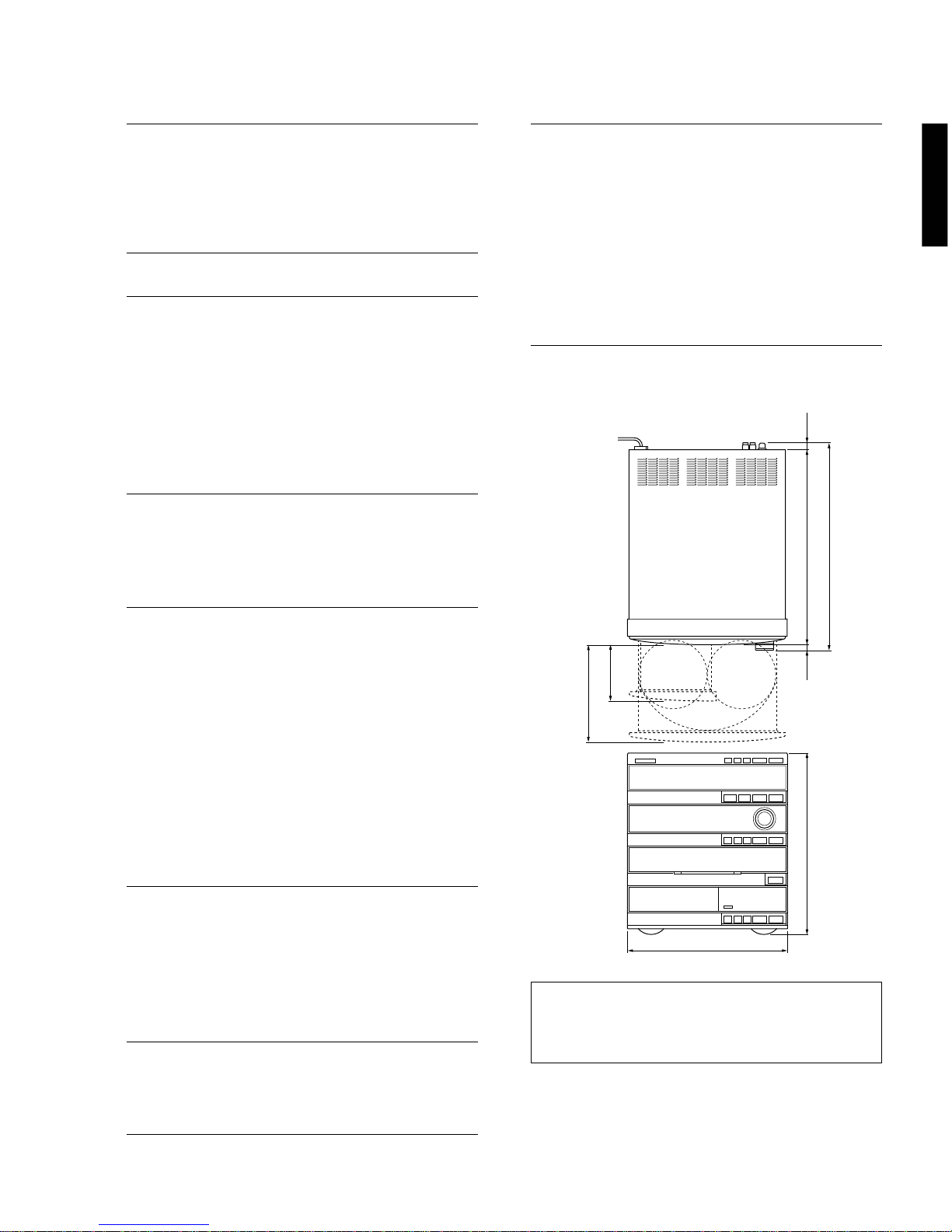
Dimensions (W X H X D)
GX-500............................................. 280 X 320 X 364mm
(11” X 12-5/8” X 14-5/16”)
NX-GX500........................................ 200 X 320 X 218mm
(7-7/8” X 12-5/8” X 8-9/16”)
Weight
GX-500............................................. 10.5kg (23 lbs. 2 oz)
NX-GX500....................................3.8kg (8 lbs. 6 oz)/each
Accessories ............................................ AM loop antenna X 1
Indoor FM antenna X 1
Remote Control Transmitter X 1
Battery (size “AA”, R06) X 2
Speaker Cord X 2
* Specifications subject to change without notice.
* Manufactured under license from Dolby Laboratories Li-
censing Corporation. “DOLBY” and the double-D symbol
Vare trademarks of Dolby Laboratories Licensing Cor-
poration.
U ...................U.S.A. model G ............ European model
C ............. Canadian model R ............... General model
A ............Australian model L ............ Singapore model
B ..................British model T....................China model
6
343(13-1/2") 12
(1/2")
9
(3/8") 364(14-5/16")
100
(3-15/16")
172(6-3/4")
280(11")
320(12-5/8")

GX-500/GX-500VCD
GX-500/VCD
■INTERNAL VIEW
Left side
Top side
qP.C.B. TUNER
wP.C.B. MAIN (5)
eP.C.B. MAIN (1)
rP.C.B. INPUT (1)
tP.C.B. MAIN (2)
yP.C.B. MAIN (3)
uP.C.B. MAIN (6)
iDECK MECHANICAL UNIT
oGX-500 P.C.B. INPUT (3)
GX-500VCD P.C.B. INPUT (2)
!0 GX-500 CD MECHANICAL UNIT
GX-500VCD VCD MECHANICAL UNIT
!1 GX-500 P.C.B. CD
GX-500VCD P.C.B. VCD (1)
!2 VCD MODULE (GX-500VCD only)
!3 P.C.B. MAIN (4) (R, T only)
7
qw
u
e r
it y
y u
!1 !2q
!3 t ri
!0o

GX-500/GX-500VCD
GX-500/VCD
■DISASSEMBLY PROCEDURES (Remove parts in the order as numbered.)
Fig. 3
Fig. 2
Fig. 1
8
1. Removal of Top Cover
Remove 11 screws ( q) in Fig. 1.
2. Removal of CD/VCD Mechanical Unit
a. Disconnect the power cord from the AC outlet.
b. Push the Friction Arm ( the bottom side of the CD/
VCD Mechanical Unit ) with the Ejecting Tool or a tool
like as shown in Fig. 2.
c. Pull the Tray forward approx. 5cm ( 2" ) and remove
the CD Lid in Fig. 2.
d. Push the Tray back to the original, closed position.
e. Disconnect the Flat Connecting Cables ( CB9 ) and
remove 3 connectors ( CB8 , CB7 and CB10 ) in Fig. 2
f. Remove 4 screws ( w) and then remove the CD
Mechanical Unit in Fig. 1.
Ejecting Tool for CD Tray (TX946040)
3. Removal of Panel Unit
a. Rotate the Loading Gear, then open the Tray and
remove the Cassette Lid in Fig. 2.
b. Push the Tray back to the original, closed position.
c. Disconnect the flat connecting cables ( CB10, CB13
and CB11 ) and remove a connector ( CB805 ) in Fig.
2.
d. Remove 6 screws ( eand r) and then remove the
Panel Unit in Fig. 1. 4. Removal of Deck Mechanical Unit
a. Remove 4 screws ( t) and then remove the Deck
Mechanical Unit in Fig. 3.
b. Remove 3 connectors ( W2, W3 and W4 ) in Fig. 3.
FRONT
Friction
Arm
q
q
q
q
Top Cover
Panel Unit
CD/VCD Mechanical Unit
q
w
w
e
e
w
r
e
CB9
CB8 CB7
CD Lid
CB10
(GX-500VCD only)
CB13
CB805
CB11
(GX-500VCD only)
CB10
Cassette Lid
Loading Gear
t
t
t
t
Deck Mechanical Unit
W3
W2
W4

GX-500/GX-500VCD
GX-500/VCD
9
Fig. 4
Fig. 5
5. Operation Check of P.C.B. CD/VCD
a. Remove the CD Mechanical Unit.
b. Remove 4 screws ( y) and then remove the P.C.B. CD/VCD in Fig. 4.
c. Place blocks (at 3 locations) to hold the CD Mechanical Unit horizontally as
shown in the Fig. 5.
d. Connect the Flat Connecting Cable ( CB9 ) and 3 connectors ( CB8, CB7
and CB10 ) in Fig. 4 and Fig. 5.
e. Connect the power plug and turn on the Power Switch.
y
VCD Module
(GX-500VCD only)
CB9
CB8
CB7
CB10
P.C.B. CD/VCD
Block
Block
P.C.B. CD/VCD
Block

GX-500/GX-500VCD
GX-500/VCD
Fig. 7
Fig. 6
Fig. 8
6. Operation Check of P.C.B. Main (1)
a. Remove the CD Mechanical Unit.
b. Remove the Panel Unit.
c. Remove the Deck Mechanical Unit.
d. Remove 5 screws ( u) in Fig. 6.
e. Remove 1 screw ( i) and then remove the P.C.B. Main (2) in Fig. 7.
f. Remove 3 screws ( o) in Fig. 7.
g. Remove 4 screws ( !0 ) and then remove the Power Transformer in Fig. 8.
h. Place the main unit on its left side (viewed from the front) and remove the Bottom Cover in Fig. 9.
i. Install the Panel unit to the main unit in Fig. 9.
j. Connect the flat connecting cables ( CB10, CB13 and CB11 ) and remove a connector ( CB805 ) in Fig. 2.
k. Connect the power plug and turn on the Power Switch.
Fig. 9
10
uu
u
i
o
P.C.B. Main (2)
!0
!0
P.C.B. Input
P.C.B. Main (1)
CAUTION
When the power to this equipment is turned on with the CD/VCD Mechanical Unit disconnected, the capacitor C255(4700/
16) of the Main P.C.B. (CD/VCD power supply section) is charged. Connecting the CD/VCD P.C.B. in this state may cause
damage to its IC. Therefore, when installing the CD/VCD Mechanical Unit, be sure to discharge the capacitor C255(4700/
16) of the Main P.C.B. before making connections. (To discharge it, short the W201 terminal +B and GND with a
resistor(270Ω1W).)

GX-500/GX-500VCD
GX-500/VCD
7. Removal of Tray & Traverse Unit
a. Remove 4 screws ( !1 ) and then remove the Clamp Bracket in Fig. 10.
b. Remove 2 screws ( !2 ) and then remove the Tray Brackets in Fig. 10.
c. Push the Friction Arm ( the bottom side of the CD Mechanical Unit ) with a screwdriver or the like and pull out the Tray
forward as in Fig. 10.
d. Remove 4 screws ( !3 ) and take out the Slider in Fig. 11.
e. Disconnect the Flat Connecting Cable ( 16P ) and connectors ( 6P ).
f. Remove the Traverse Unit in Fig. 11.
!1
!1
CD Mechanical Unit
Friction
Arm
Clamp Bracket
Fig. 11
●Precaution for Installation of Tray
Be sure to fit the shaft of the Friction Gear into
the groove in the Tray.
●Installation of Traverse Unit & Slider
a. Fit the Traverse Unit into the Chassis.
b. Turn the Cam Gear until its Guide Pin comes to the
position as shown in Fig. 11.
c. Fit the Slider into the Traverse Unit. Set the Spring of
the Slider so that it holds down the Guide Pin of the
Cam Gear (as shown in Fig. B).
(Press the Spring of the Slider once and release it,
and it will hold down the Guide Pin of the Cam Gear.)
d. After installation, check that the Clamp moves up and
down by turning the Load Gear.
Fig. B
Tray
Tray Bracket
!2
Spring
Spring
Spring Load Gear
FRONT
Groove
Guide Pin
OK NG
Tray
Bracket
Friction
gear
Shaft
Tray
Slider
Traverse
Unit
Guide
Pin
Cam Gear
Fig. 10
!3
no marking
side
!3
Guide Pin
Cam Gear
Traverse
Unit
Spring
Slider
Fig. A
11

GX-500/GX-500VCD
GX-500/VCD
Fig. 14
Disc Table
19.4mm
Fig. C
Pick-up Head Gear A
Sled Shaft
Sled Shaft
Stopper
Fig. 12
9. Removal of Cassette Mechanism
Remove 4 screws ( !4 ) and then pull out the Cassette
Mechanism in Fig. 13.
10.Removal of Main Motor
Remove 2 screws ( !5 ) in Fig. 13.
11.Removal of Pinch Roller
Detach the hook and then remove the Pinch Roller
in Fig. 14.
12.Removal of Head Ass’y
a. Remove 1 screw ( !6 ) and then remove the Relay
P.C.B. in Fig. 14.
b. Remove 2 screws ( !7 ) and then remove the Head
Ass’y in Fig. 14.
* Perform the adjustment of azimuth after installing
the Head Ass’y.
8. Removal of Pick-up Head
a. Remove the Gear A in Fig. 12.
b. Pull out the Sled Shaft and remove the Pick-up Head
in Fig. 12.
●Check that the disc table height is as specified
below.
Fig. 13
12
!4 !4
!4 !4
!5 !5
!6!7 !7
Pinch Roller (L) Pinch Roller (R)
Hook Hook
Head Ass'y

GX-500/GX-500VCD
GX-500/VCD
DISPLAY
VOL MIN
VOL 01
VOL 02
VOL 03
VOL 04
VOL 05
VOL 06
VOL 07
VOL 08
VOL 09
dB
– ∞
–79
–73
–68
–64
–61
–59
–58
–57
–56
DISPLAY
VOL 10
VOL 11
VOL 54
VOL 55
dB
–55
–54
–11
–10
DISPLAY
VOL 56
VOL 57
VOL 58
VOL 59
VOL 60
VOL 61
VOL 62
VOL 63
VOL 64
VOL MAX
dB
–9
–8
–7
–6
–5
–4
–3
–2
–1
0
■VOLUME RANGE
○○○○○○○○
1dB step
NOTE) When VOLUME is at minimum, MUTE of AMP is on.
■SYSTEM CONTROL CHECK
wFUNCTION →CD ?
DISC No. display on?
↓
no
In case that CD doesn’t play : [RECEIVER →CD]
(SYSCK, CDCE, SYSO) NG
In case that DISPLAY doesn’t change : [CD →RECEIVER]
(SYSI) NG
yes
qFUNCTION AUX/MD is selected
CD PLAY KEY ON (remote control transmitter)
↓
CHECK OK
13
SYSCK: Pin 20 of IC8
CDCE: Pin 25 of IC8
SYSO: Pin 21 of IC8
SYSI: Pin 22 of IC8

GX-500/GX-500VCD
GX-500/VCD
■TEST MODE
To facilitate inspection, measurement and location of any faulty point, 6 types of built-in Test Mode are provided, one
for each section.
• System Test Mode : Test mode for the system section. It is also used when entering the test mode for each section.
• Receiver Test Mode : Test mode for the receiver section
• Tape Test Mode : Test mode for the deck section
• CD Test Mode : Test mode for the CD section
• MD Test Mode : Test mode for the MD section (unused for this unit)
• All Function Test Mode : Test mode for all functions
■SYSTEM TEST MODE
This test mode is used for the system section. Also, this mode must be executed first when entering the test mode
for each section.
Starting Procedure
In the STANDBY mode, press the STANDBY/ON button while pressing the RANDOM button and the PLAY/
PAUSE(CD) button simultaneously. Once the SYSTEM TEST MODE is set, causal factors for the previous power
off appear on the FL display.
Causal factors for power off at starting
Display Description
<Key Operate Power off by button operation
<Off Timer Power off by Off Timer setting
<Sleep Timer Power off by Sleep Timer function
<Auto Off Power off by Auto Power Off function
<I-Protect Power off by detection of an abnormal current value
<V-Protect Power off by detection of an abnormal voltage value
<Temp Over Power off by detection of an abnormal temperature value
<AC Cut Power off by AC power cut
<?? Unknown
Operation Procedure (Selection/finalizing of TEST MODE for each section)
1) Select the TEST MODE by the section name, pressing the wINPUT (up) or qINPUT (down) button.
Display Description Ref. page
<Key Operate Causal factors for power off are displayed. 14
(This state is available immediately after starting.)
Test RECEIVER RECEIVER TEST MODE 15
Test TAPE TAPE TEST MODE 16
Test CD CD TEST MODE 17
Test MD MD TEST MODE (Unused for this unit) —
Test All Func ALL FUNCTION TEST MODE 18
Escape Test The test mode is canceled. —
2) Pressing the MUSIC button will shift the mode to the selected test mode.
For the details of the selected test mode, refer to the Ref. page in the above step 1).
14

GX-500/GX-500VCD
GX-500/VCD
No. & DISPLAY
01 G , E , TEST
02 FL + CLEAR
03 FL FULL
04 APO - ON/OFF
05 RDS - OFF/ON
06 A , PS - ON/OFF
07 A , M , - RDS/ALL
08 CT > C - ON/OFF
09 L > CT - ON/OFF
10 PSR2 - ON/OFF
11 RTBL - ON/OFF
12 SEC - OFF/ON
13 Temp
14 PEAK - ON/OFF
15 AMPC - OFF/ON
16 CDCH - ON/OFF
17 REM CODE
18 L , EN - ON/OFF
19 ALL CH >
20 RDS E / F
21 SUR TEST
22 KEYC - OFF/ON
23 AM - IF
24 CANCEL
25 DEST
FUNCTION
Equalizer check mode
FL display full lighting,
RAM CLEAR
FL display full lighting
PURPOSE & OPERATION
Used to check EQ.
Pressing the STANDBY/ON button will set the Equalizer Test mode.
For the details, refer to page 16.
Used for lighting of all display segments and clearing of RAM. (Note that
the user memory will be cleared.)
At the first pressing of the STANDBY/ON button, all display segments light
up and at the second pressing, MEMORY and M-CLEAR light up for 2
seconds and RAM of CPU is initialized. (The product mode is restored.)
(Presetting of the tuner becomes the manufacturer preset state.)
Used to check lighting of all display segments.
At the first pressing of the STANDBY/ON button, all display segments light up and
at the second pressing, this mode is canceled. (The product mode is restored.)
Do not use No. 04 to 23 functions as they are not for servicing.
Used to cancel the test program.
(The product mode is restored when the STANDBY/ON button is pressed.)
Destination display mode
■RECEIVER TEST MODE
When RECEIVER TEST MODE is set through SYSTEM TEST MODE, “01 G.E.TEST” appears on the FL display. (01
is the test program No.)
Test programs from 01 to 25 are incorporated in RECEIVER TEST MODE.
Operation Procedure (Selection/execution of Test Program)
1) Select the test program by pressing the rTAPE (up) or eTAPE (down) button.
2) Pressing the STANDBY/ON button will execute the selected test program.
3) Repeat selection/execution of the test program as necessary.
15

GX-500/GX-500VCD
GX-500/VCD
Preset group
A
B
C
D
E
P1 P2 P3 P4 P5 P6 P7 P8
CAUTION : When executing Test program No. 2 RAM CLEAR, be sure to write down the preset memory contents of the
tuner, using a table like the one shown below. Execution of RAM CLEAR will set the memory contents of the
tuner back in the factory preset state which means that all the memories preset by the user will be erased.
●MAKER’S PRESET
NOTE 1) PRESET PAGE ............................................ A : FM B : AM C : FM D : AM E : FM
BAND
FM (MHz)
AM (kHz)
MARKETS
U, C, R, T (100k/10k)
A, B, G, L, R, T (50k/9k)
U, C, R, T (100k/10k)
A, B, G, L, R, T (50k/9k)
8
107.9
107.90
1440
1440
7
106.1
106.10
1350
1350
6
88.1
88.10
900
900
5
107.9
108.00
1710
1611
4
101.5
101.50
530
531
3
87.5
87.50
1400
1404
2
95.1
95.10
1080
1080
1
98.1
98.10
630
630
PRESET No.
16
Equalizer test mode (Test program No. 01)
When the equalizer test mode is set, “GEQ - xxx” is displayed. “xxx” represents the 3 band value of GEQ.
It is possible to set the GEQ value directly, using the buttons on the remote control unit.
Example : To obtain flat
GEQ - 6 6 6
Low tone Intermediate tone High tone
Displayed value 0 123456789ABC
Gain (dB) -12 -10 -8 -6 -4 -2 0 +2 +4 +6 +8 +10 +12
Operation Procedure
• To set a value for each band
[ 0 ] to [ 9 ], [ A(TIME) ], [ B(PROG) ], [ C(R.TIME)]
• To set all bands to Min (-12dB)
[ D(EDIT) ]
• To set all bands to Max (+12dB)
[ E(+10) ]
• To cancel this test mode, press the STANDBY/ON button. (The production mode will be restored.)
■TAPE TEST MODE
When TAPE TEST MODE is set through SYSTEM TEST MODE, “Tape Test XXXX” appears on the FL display.
(XXXX is the counter value.)
The operation condition of the deck section will be as follows.
• When the reverse mode is set to “endless”, the number of playback repetition becomes unlimited.
(It is set to “8 “ times in the product mode.)
• When in the REC mode, AUX/MD is used automatically for the input source.

GX-500/GX-500VCD
GX-500/VCD
The CD TEST MODE is enabled. Each button operates as follows for each mode. The MODE No. is increased by
pushing "+10"button.
Button
" 0 "
" 1 "
" 2 "
" 3 "
" 4 "
" 5 "
" 6 "
" 7 "
" 8 "
" 9 "
Button
" 0 "
" 1 "
" 2 "
" 3 "
" 4 "
" 5 "
" 6 "
" 7 "
" 8 "
" 9 "
MODE 4 MODE 5 (GX-500VCD only)
Feed forward (outer direction) CD-ROM module load
Feed backward (inner direction) CD-G module load
Rotate the disc motor Decoder play command
Retard the disc motor Decoder pause command
port TBLL ←Low, Decoder abort command
port TBLR ←High
port TSLW High/Low alternate Decoder soft reset
Tray port control (open/close) Decoder hard reset
Line mute on/off —
——
Jump to Test mode 1 —
MODE 1 MODE 2 MODE 3
Open/close the tray Focus search Cancel adjust pass *2
Clamp up/down Play (PLL) Auto adjustment mode 1 *1
Tracking Offset, Focus Offset,
Focus Gain
DISC change Play (without PLL) Auto adjustment mode 2 *1
Tracking Balance, Tracking Gain
Mechanism home process Focus on, Tracking off, Feed off Auto adjustment mode 3 *1
Focus Gain, Tracking Gain,
Focus Balance
Jump to test mode 4 +10 track kick Read and display the servo
coefficient
Tray close, Clamp down –10 track kick Displayed servo coefficient
address up
— +1 track kick Displayed servo coefficient
address down
Enter normal operation –1 track kick Displayed servo coefficient
(without mecha. INIT.) increment
Enter normal operation +30 track kick Displayed servo coefficient
decrement
Start TEST REPEAT –30 track kick Send the displayed servo
(Do not use this function as coefficient *2
it is not for servicing.)
*1 “Adj-” lights during the
adjustment and disappears at
the end of the adjustment.
*2 When the mode is reset to the
Production Mode after the servo
coefficients are renewed by this
operation, auto adjustment is not
available unless the auto
adjustment pass function is
cancelled.
Open/close the tray
Clamp up/down
Controls for the tray, the disc table and clamping stop. STANDBY command for the servo system.
Play (PLL)
Feed forward (outer direction)
Feed backward (inner direction)
Tray close, clamper down
OPEN/CLOSE
DISC CHANGE
a(STOP)
w/d
(PLAY/PAUSE)
y
t
DISC 1
The following button functions are not changed in the test mode No.
[VCD Module condition check]
If the VCD module is in a good condition, the blue background appears on the monitor screen when in the CD test mode.
If the blue background does not appear, the possibility is that the VCD module has failed.
NOTE: None of the components of the VCD module can be supplied separately. Only a VCD module unit (VZ150200) is available.
When CD TEST MODE is set through SYSTEM TEST MODE, “00STM100: 00” appears on the FL display.
■CD TEST MODE
17

GX-500/GX-500VCD
GX-500/VCD
■ALL FUNCTION TEST MODE
When ALL FUNCTION TEST MODE is set through SYSTEM TEST MODE, “AUX Digital” appears on the FL display.
The operation condition in this mode will be as follows.
• AUX/MD is used as the input source of the receiver section, which is then set to the Dolby Pro Logic mode (GX-
500VCD only).
• When a CD is loaded, Full Repeat Play is executed automatically for it.
• When a cassette tape is loaded, Endless Rec Play is executed by the cassette deck automatically.
■CD ERROR MESSAGES
Error message can be obtained on the display by pushing STOP and TIME buttons simultaneously when CD has
stopped (sometimes with the tray open) by an error.
STATE
PLAY
SCAN
PAUSE
SEARCH
PLAY
SCAN
PAUSE
SEARCH
LOAD, SEARCH
LOAD, SEARCH
SEARCH, PLAY, PAUSE
SEARCH
STOP
LOAD, EJECT, CHANGE
PLAY
SCAN
PAUSE
SEARCH
LOAD, DISC CHANGE
INDICATION
E-10
E-20
E-30
E-70
E-11
E-21
E-31
E-73
E-04
E-14
E-35
E-06
E-47
E-57
E-77
E-18
E-28
E-38
E-48
E-68
E-AA
E-AB
E-AC
E-AD
E-AE
E-AF
MN ERR
CONTENTS OF ERROR
CD fails in the disc data reading after the state shift.
CD fails in the disc data reading.
CD fails in the TOC data reading.
Tracking servo is not effective at the disc motor servo PLL.
Disc motor servo PLL is not effective.
CD fails in focus search.
CD fails in escaping from the lead-in area.
The inner limit switch does not operate at the feed inner control.
CD fails in recovery from the focus out.
Clamp down switch does not operate at the clamp down control.
Clamp up switch does not operate at the clamp up control.
Close switch does not operate at the tray close control.
Open switch does not operate at the tray open control.
CD fails in the table control.
CD fails in the mecha. home process.
MN662741 does not give response of SENSE with resetting by the units
microcomputer.
When "MECHA ER" message appears on the display;
Possible symptoms are, the clamp does not move up or down, the table does not turn, mecha. sensor switch malfunctions, etc.
The normal operation may be restored by tuning off the power once and then on again. If it does not work in this way, disas-
semble the CD mechanical unit and investigate the cause of the failure.
18

GX-500/GX-500VCD
GX-500/VCD
■CD STANDARD OPERATION CHART
Press OPEN/CLOSE key.
Forced feed return operation.
Clamp down operation.
Disc table reset.
Tray open.
Tracking Offset auto ADJ. (only POWER ON)
Focus Offset auto ADJ. (only POWER ON)
Load a disc in “DISC 1”.
Press PLAY key or push the tray.
Tray closed.
Table rotate.
Disc research.
Disc mechanism unit clamped up.
Feed inward switch research.
Laser ON.
Disc scan.
FOCUS Gain roughADJ.
FOCUS Search operation.
FOCUS LOCK servo ON.
Spindle motor accelerated.
TRACKING servo ON.
Disc servo ON
VCO lock.
Tracking Gain rough ADJ.
Tracking Balance ADJ.(only Tray OPEN/CLOSE)
“OPEN” appears in the TIME indicator.
“TRV” signal is output until detection of LIMIT switch.
DISC “1”is turned to DM clamp position.
LDON = “H” (IC5, 40 pin)
FLOCK = “H” →“L” (IC11, 8 pin)
TLOCK = “H” →“L” (IC11, 11 pin)
FOCUS BALANCE ADJ.
FOCUS GAIN ADJ.
TRACKING GAIN ADJ.
19
A
Other manuals for GX-500
1
This manual suits for next models
2
Table of contents
Other Yamaha Stereo System manuals

Yamaha
Yamaha TSX-140 User manual

Yamaha
Yamaha MCR-330 User manual

Yamaha
Yamaha TSX-120 User manual

Yamaha
Yamaha TSX-20 User manual

Yamaha
Yamaha CRX-M5 User manual

Yamaha
Yamaha CDX-E200 User manual

Yamaha
Yamaha TSX-B237D User manual

Yamaha
Yamaha CC-90 User manual

Yamaha
Yamaha GX-700 User manual

Yamaha
Yamaha GX-500 User manual

Yamaha
Yamaha CRX-E500 User manual

Yamaha
Yamaha YST-99CD User manual

Yamaha
Yamaha TSX-10 User manual

Yamaha
Yamaha TSX-W80 User manual

Yamaha
Yamaha CRX-E150 User manual

Yamaha
Yamaha TSX-B15 User manual

Yamaha
Yamaha GX-900 User manual

Yamaha
Yamaha IF2108 User manual

Yamaha
Yamaha CRX-E200 User manual

Yamaha
Yamaha CRX-E300 User manual