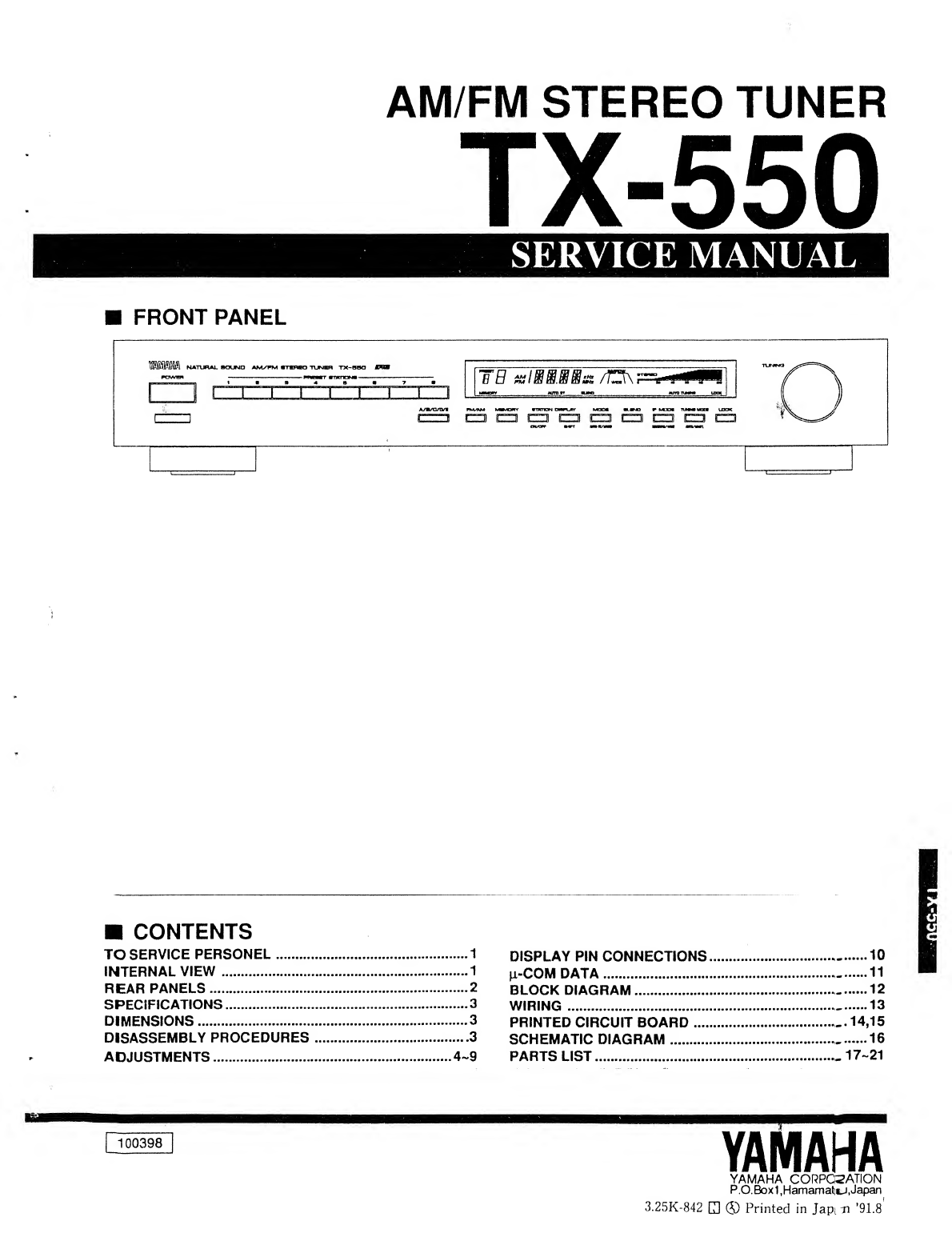
Yamaha TX-550 User manual

AM/FM STEREO TUNER
TX-550
SERVICE MANUAL
FRONT PANEL
CONTENTS
TO SERVICE PERSONEL 1
INTERNAL VIEW 1
REAR PANELS 2
SPECIFICATIONS 3
DIMENSIONS 3
DISASSEMBLY PROCEDURES 3
ADJUSTMENTS 4~9
DISPLAY PIN CONNECTIONS 10
fi-COM DATA -11
BLOCK DIAGRAM 12
WIRING 13
PRINTED CIRCUIT BOARD -.14,15
SCHEMATIC DIAGRAM 16
PARTS LIST 17-21
YAMAHA
YAMAHA CORPORATION
P.O. Box 1.Hamamati^.Japan
3.25K-842 Q®Printed in Japin ’91.8

TX-550
TX-550
EQUIPMENT AC LEAKAGE TESTER
UNDER TEST OR EQUIVALENT
INSULATING TABLE
TO SERVICE PERSONNEL
1.Critical Components Information,
Components having special characteristics are
/L marked and must be replaced with parts
having specifications equal to those originally
installed.
2. Leakage Current Measurement (For 120 VModel
Only). When service has been completed, it is
imperative that you verify that all exposed conduc-
tive surfaces are properly insulated from supply
circuits.
•Meter impedance should be equivalent to 1500
ohm shunted by 0.1 5pF.
•Leakage current must not exceed 0.5 mA.
•Be sure to test for leakage with the AC plug in
both polarities.
•POLARIZATION
This product is equipped with apolarized alternat-
ing current line plug (a plug having one blade
wider than the other ). This plug will fit into the
power outlet only one way. This is asafety
feature. (U,C model only)
WARNING: CHEMICAL CONTENT NOTICE!
Avoid prolonged, unprotected contact between
solder and your skin! When soldering, do not inhale
solder fumes or expose eyes to solder/flux vapor!
If you come in contact with solder or components
located inside the enclosure of this product, wash
your hands before handling food.
DO NOT PLACE SOLDER. ELECTRICAUELEC-
TRONIC OR PLASTIC COMPONENTS IN YOUR
MOUTH FOR ANY REASON WHAT SO EVERI
The solder used in the production of this product
contains LEAD. In addition, other electrical/elec-
tronic and/or plastic (where applicable) components
may also contain traces of chemicals found by the
California Health and Welfare Agency (and possibly
other entities) to cause cancer and/or birth defects or
other reproductive harm.
INTERNAL VIEW
T T T
<© oe®
OTuner circuit board (3)
QTuner circuit board (1)
©FM Front-end pack
OTuner circuit board (6)
0Tuner circuit board (4)
©Tuner circuit board (2)
0LCD circuit board
0Tuner circuit board (5)
1

TX-550
REAR PANELS
•U.S.A and Canadian Models

TX-550
TX-550
SPECIFICATIONS
FM SECTION
Tuning Range
[U.S.A., Canada and General models]
87.5 to 108 MHz
[U.K., Australia, Europe and General models]
87.5 to 108 MHz
50 dB Quieting Sensitivity (IHF) [Except Europe
model]
75 ohms Mono 1.55 (15.1 dBf)
75 ohms Stereo (NARROW) .... 21 jxV (37.7 dBf)
Usable Sensitivity
[Except Europe model]
75 ohms. 1kHz, 100% mod. (30 dB S/N
Quieting) •0.8 ^.V (9.3 dBf)
[Europe model] (DIN)
75 ohms Mono (S/N 26 dB) 0.8 m-V
75 ohms Stereo (S/N 46 dB) 22 i^V
Image Response Ratio
[Except Europe model] 40 dB
[Europe model] 75 dB
IF Response Ratio
[Except Europe model] 90 dB
[Europe model] 75 dB
Spurious Response Ratio 70 dB
fiJSA Suppression Ratio 55 dB
Capture Ratio 1.5 dB
DIMENSIONS
Alternate Channel Selectivity (NARROW)
[Except Europe model] 85 dB
Selectivity (two signals, 40 kHz Dev., ±300 kHz.
NARROvio
[Europe model] 70 dB
Signal-to-Noise Ratio
[Except Europe model] (IHF)
Mono 90 dB
Stereo 85 dB
[Europe model] (DIN-NOISE RMS)
Mono (40 kHz Dev.) 83 dB
Stereo (40 kHz Dev.) 79 dB
Harmonic Distortion (1 kHz, WIDE)
[Except Europe model]
Mono/Stereo 0.02%/0.03%
[Europe model (40 kHz Dev.)]
Mono/Stereo 0.02%/0.03%
Stereo Separation (WIDE)
[Except Europe model] 1kHz 52 dB
[Europe model] 1kHz 45 dB
Frequency Response
[Except Europe model]
30 Hz to 13 kHz 0±0.5 dB
20 Hz to 15 kHz 0±1.5 dB
[Europe model]
20 Hz to 15 kHz 0±0.5 dB
AM SECTION
Tuning Range
[U.S.A., Canada and General models]
530 to 1.710 kH;
[U.K., Australia and Europe models]
531 to 1,611 kH:
Usable Sensitivity 100 ^.V/rr
Selectivity 32 dE
Signal-to-Noise Ratio 50 dE
image Response Ratio 40 dE
Spurious Response Ratio 50 dE
Harmonic Distortion: 400Hz 0.3*?(
AUDIO SECTION
Output Level/Impedance
FM (100 %mod. 1kHz)
[Except Europe model] 700 mV/2 8k-ohm*
[Europe model] 500 mV/2,8 k-ohms
AM (30% mod. 400 Hz) 180 mV/2.8 k-ohms
GENERAL
Power Supply
U.S.A. and Canada models 120V, 60 H2
Europe model 230V, 50 Hi
U.K. and Australia models 240V, 50 Hi
General model 110-120/220-240V, 50/60 Hi
Power Consumption 10W
Dimensions (W xHxD) ... 435 x72.5 x320 mrr
(17-1/8" x2-7/8" X12-5/8"';
Weight 3.1 kg (6 lbs. 13 oz.)
Accessories Audio connection core
AM loop antenna/indcor FM antenns
Specifications subject to change without notice.
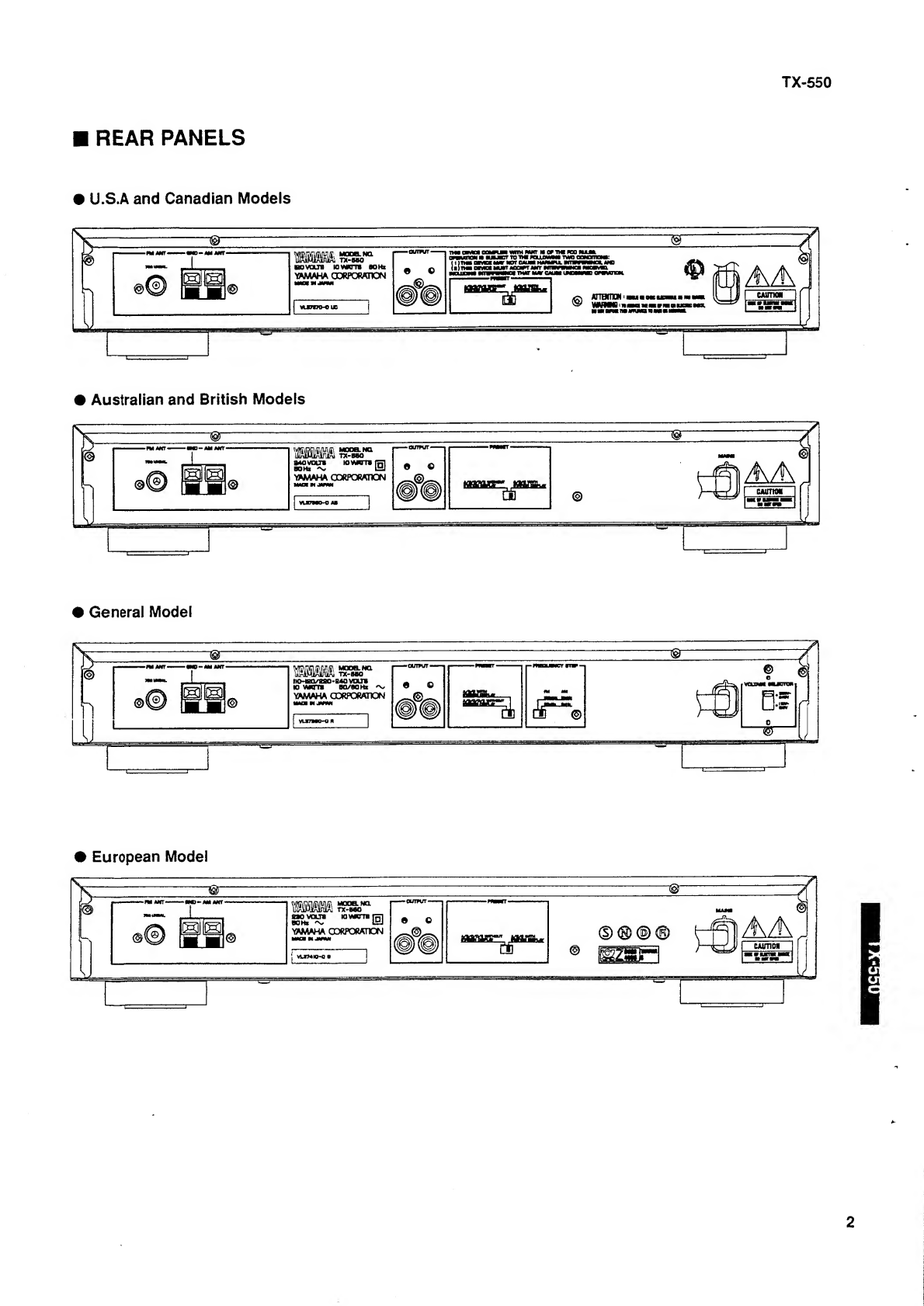
UU.S.A. model
CCanadian model
AAustralian model
GEuropean model
BBritish model
RGeneral model
-435(17-1/8’ 50(1-15/16”)^
O60 (2-3/8")
, I
'i 16(5/8") unit :mm (inch)
DISASSEMBLY PROCEDURES
1.Removal of Top Cover
Remove 4screws ®and 2screws d), and slide
the Top Cover back. ^
2. Removal of Front Panel
a. Remove 3screws d), 2screws @and 6
connectors, and pull the Front Panel forward.
3

TX-550
ADJUSTMENTS
1.Before adjustment
1) After the power switch is pushed on, wait for 5
minutes befor measuring to be sure of the most
stable operation.
2) Adjust the OSC coil and IFT with non-ferrous
screw driver.
3) Set the switches to the following positions.
TUNING MODE AUTO
4) Make the AM section adjustments after having
finished the FM section adjustment.
5) OdBp =1^lV Ex; 60dBp =1mV
XdBp =(X + 11.2)dB/ Ex: 70dBp =81 .2dB/
(POWER SUPPLY CHECK)
Check that the following voltages are obtained respectively across each test point and ground on tuner circuit.
Test Point Rating or standard Remark
+12.0 V(Q29 Emitter) +12.5 V± 0.5 VMake sure that AC line
voltage comes within: Models
u,c
G
AC line voltage
120 V± 10%
230 V± 10%
+6.0 V(Q30 Emitter) +6.0 V+ 0.5 V
+30.0 V(Q35 Emitter) +28.0 V± 1.0 VA, B
R
240 V± 10%
110/120/220/240V±10%
-6.0V(D23 Anode) ~6.5 V±0.5V
2. Measuring instruments abbreviation
FM SG :FM signal generator
SSG :Stereo signal generator
AM SG :AM signal generator
DIST. M:Distortion meter
FC :Frequency counter
ACVM :AC voltage meter
DCVM ;DC voltage meter
•TEST POINTS
iZERO BALANCE I
1STEREO DISTORTION] FRONT-END IFT
1SEPARATION |T1
VR4 VR3
WIDE
VR6 [H
0JA [0]L3 VR2 VR1
m
r^VCI !mono DISTORTION NARROW
DISCRIMINATOR BALANCE |
ISIGNAL METER I
^12 V-6V +30 V
B- 0- ^
Q29 Q30 Q35 23

TX-550
TX-550
(Confirmation of preset)
CAUTION:
Using atable as shown below, write down the contents of the memory
presets in the tuner before setting to the test program mode.
(This is because setting to the test program mode sets the tuner
memory content in the state preset by the manufacturer and erases
all the memory preset by the user,)
Upon completion of the test program, set to the tuner mode again and
enter the preset memory as written In the table.
Preset Group P1 P2 P3 P4 P5 P6 P7 a
A
B
C
D
E
•Turn the POWER switch on while pressing the
preset keys “1", “2" and “3" simultaneously.
Confirm that the frequencies described below are
changed to the preset values. (Press P8 to reset
the test mode. To preset, leave the keys as they
are.)
*Total of 40 stations, P1 to P8 for each Ato Eare
reset to the preset value.
P1 P2 P3 P4 *P5 P6 P7 P8
A/ U. C87.5M 95.1 98.1 101.5 108.0 88.0 106.0 107.9
C/E A, B, G, R87.5M 95.1 98.1 101.5 108.0 88.0 106.0 107.9
B/D u, c630k 1080 1440 530 1680 900 1350 1400
A, B, G, R630k 1080 1440 531 1680 900 1350 1404
Station name
For the Rmodel, AM frequency step 9kHz to
(from) 10 kHz, and FM frequency step 100 kHz to
(from) 50 kHz can be switched.
Setting of the Function
The mode is changed to
MODE AUTO ST, BLEND OFF,
IF MODE WIDE.
(Confirmation of LCD unit)
Confirmation of the display
1The test mode is entered and all the segments of the
LCD light when the POWER switch is turned on while
pressing “PI ", “P2" and “P3" simultaneously.
2After 1,the display mode is changed by pressing the
following keys.
1P2 All turned off mode (All the segments are turned
off)
2P3 “8” is lit at the center position.
3P8 The test mode is switched to normal mode.
(FM TUNER SECTION)
•Use 15 kHz L.P.F. to measure the output.
•100% modulation means that the Frequency
Deviation is 75 kHz. (R, U, C, A, B)
•For the Gmodel. Frequency Deviation is 40 kHz
•For the G, Bmodels, install the Matching Trans-
former and connect FM SG.
•Cnnectiondiagram (Measuring instruments)
1)Zero balance adjustment
3) Monaural distortion adjustment
4) Stereo distortion adjustment/separation
adjustment YLF-1S
5) Full-scale signal quality meter adjustment
5

TX-550
Step Item to be
Adjusted Connection
terminal
Instrument
required
1Zero balance FM ANT FM SG, SSG
98.1MHz 70dBn
MONO 100Hz
100% modulation
TP1 <-^TP2 DCVM
2Discriminator
balance
FM ANT FM SG
88MHz
MONO 100Hz
100% modulation
FMs ^NVcc DCVM
3Monaural distortion FM ANT FM SG
98.1MHz
70dB^i
MONO 100Hz
100% modulation
OUTPUT
L. RDIST. M
4Stereo distortion
WIDE
Stereo distortion
NARROW
FM ANT FM SG. SSG
98.1MHz
70dBp
STEREO Lor R
1kHz, 100%
modulation
OUTPUT
L. RDIST. M
5Verification of
monaural distortion
FM ANT FM SG
98.1MHz
70dBp
MONO
1kHz, 100%
modulation
OUTPUT
L. RDIST. M
6Separation FM ANT FM SG, SSG
98.1MHz
70dBp
STEREO Lor R
1kHz, 100%
modulation
OUTPUT
L, RACVM
7Verification of zero
balance 75Q
FM ANT Same as step 1
Adjustment
locations
Adjustment
method
Adjust T1, so that
voltage between
TP1 and TP2 may
be OV ±50mV
when tuned to
generator.
Adjust T4, so that
voltage between
FMs and NVcc
may be OV ±50mV
when tuned to
generator.
Reduce distortion
to minimum.
(WIDE mode)
Rating or standard
Less than ~54dB
(WIDE mode)
0.16%
Reduce output
level to minimum.
Separation more than
36dB
(WIDE mode)
Same as step 1If not, return to stepi
and readjust

TX-550
TX-550
Step Item to be
Adjusted Connection
terminal
Instrument
required Adjustment
locations Adjustment
method Rating or standard
8Verification of
Discriminator
balance
75n
FM ANT Same as
atep 2Same as
atep 2
If not, retarn to step 2
and readjust.
FMs NVcc DCVM
9Full-scale signal
quality meter 75U
FM ANT FM SG, SSG
98,1 MHz
45dBp
STEREO L, R
1kHz, 100%
modulation
VR5 Adjust VR5 until all
signal quality
indicators light up.
(WIDE mode)
10 Verification of
Blend
75Q
FM ANT FM SG, SSG
98.1MHz
70dB^i
STEREO L, R
1kHz, 100%
modulation
Check that when
blend switch is
turned on,
separation
decreases.
(WIDE mode)
j
11 Verification of auto
tuning
75Q
FM ANT FM SG
98.1MHz
26dBp
MONO 1kHz
30% modulation
TUNING knob ;Automatic
reception should
be available when
the tuning knob is
rotated UP and
DOWN.
Audio muting should
be applied during
tuning.
(AM TUNER SECTION)
•Make the AM section adjustments after having
finished the FM section adjustment.
•Connect the AM loop antenna to the AM ANT terminal.
•Connect the AM dummy antenna for adjustment to AM SG.
•Check that the AM SG precision is within ±0.1 kHz.
AM DUMMY ANTENNA CONNECTION
AM loop ar»t?o
R1.
1
150 >
1J
TEST POINTS
IBIBSHnSial
7

TX-550
Step Item to be
adjusted
Connection
terminal Instrument required Adjustment
locations Adjustment method Rating or standard
1Sensitivity AM ANT AM dummy antenna
AM SG
630kHz
1080kHz
1440kHz
60dB^i
MONO 400Hz
30% MOD.
T2 Adjust T2 at 630kHz,
1080kHz, 1440kHz to make
the output reading maximum
when the preset CH B-1, B-2
and B-3 are received
accordingly.
OUTPUT ACVM
2Verification of
Signal meter
AM ANT AM dummy antenna
AM SG
1080kHz
lOOdB^
400Hz, 30% MOD.
All signal quality indicators
light up.
3Verification of
Signal meter AM ANT AM dummy antenna Check that all the signal
meters are turned off.
4Verification of
auto-search
AM ANT AM dummy antenna
AM SG
1080kHz
60dB^i
400Hz, 30% MOD.
Check that auto search
reception is possible with the
TUNING knob.
Tuning MODE
AUTO
(DIGITAL CONTROL SECTION)
Step Confirmation Item Connection
terminal Instrument required Operation key Confirmation method
1Preset memory 75Q
FM ANT FM SG, SSG
98.1MHz ±1kHz
70dBp STEREO, L,
RIkHz. 100%
MOD.
FM, AM
TUNING MODE
TUNING
{UP or DOWN)
MEMORY
PRESET
STATION
P1-P8
1.Receive FM 98.1MHz by means of auto
search.
2. Press MEMORY key MEMORY indicator
flashes about 5seconds.
3. Select Awith A/B/C/D/E SW. “A” lights.
4. Press PI “1” lights and MEMORY
indicator goes off. MEMORY indicator
goes OFF A1 indicator lights.
AM ANT AMSG
AM dummy antenna
1080kHz ±0.1kHz
80dB^
400Hz, 30% MOD.
A/B/C/D/E
5. Receive AM 1080kHz.
6. Press MEMORY key MEMORY indicator
flashes about 5seconds.
7. Select Bwith A/B/C/D/E SW. "B" lights.
8. Press PI -> “1 ’’ lights and MEMORY indica-
tor goes off. MEMORY indicator goes
OFF B1 indicator lights.
9. Press A1 and B1 and check that Contentis
read out properly.
A1 and B1 light.
2Tuning modes Same as step
1
Same as step 1FM
TUNING MODE
TUNING
{UP or DOWN)
Tune to FM 98.1MHz and check that during
MAN'UMONO reception FM is forced
monaural.
AUTO ST indicator goes off.
STEREO indicator goes off.
8

TX-550
TX-550
(DIGITAL CONTROL SECTION)
1
i
1
step Confirmation
Item Connection
terminal instrument required Operation key Confirmation method
3Lock confirmation Confirm that the frequency does not change
by turning the TUNING knob when the LOCK
SW is pressed during STATION DISPLAY
SW OFF mode.
LOCK indicator lights.
4IF mode
confirmation Confirm that the IF mode switches to MAN'L
automatically when the NARROW/WIDE SW
is pressed after the preset button 1is
selected and AUTO is selected with the
AUTO/MAN’LSW. Confirm that each display
changes according to the changed condition.
Also, confirm that the mode changes to
NARROW when the antenna Input is turned
down slowly from the AUTO WIDE tuning
mode.
5STATION
DISPUVY
confirmation
i
“”is displayed on the display window
when the ON/OFF SW of the STATION
DISPLAY is tuned ON. After '* Is
displayed, first column flashes and “A” is
displayed when the SHIFT SW is pressed
(during AUTO or MAN'L tuning). The display
changes A, B, C, ... by turning the TUNING
knob clockwise, and A, 0, 9, 8, ... by turning
the knob counterclockwise. After desired
number or character Is selected, the second
column flashes and “A” is displayed when the
SHIFT SW is pressed. Select desired
character or number for all four columns and
program into the memory. Confirm that the
programmed characters and/or numbers are
displayed when they are selected.
(When the rear panel SW is A, B, or C)
6Last station
memory PRESET STATION
PI
A/B/C/D/E
1. Press A1 FM 98.1MHz is shown.
2. Turn POWER key OFF.
3. After 5seconds, turn POWER key on.
4. Check that A1 content is read out.
^A1 indicator lights. FM 98.1MHz is
displayed.
7Remote control
function confirma-
tion
Confirm that the A/B/C/D/E can be switched
and 1-8of the preset station keys can be
selected directly with the optional remote
control.
Confirm that the A/B/C/D/E can be switched
and 1-8can be selected (up and down station
selection) with the RS remote control (custom
code 7A and 7E).
Operating distance: more than 7m(without
obstacie).


TX-550
TX-550
i^i-COM DATA (LC66306A-4725:IC2)
(4-bit Microcomputer)
POO [
P01 ^
P02 ^
P03 [
P10 QI|
P11 CL
P12 CE
P13 CL
SIO/P20 nr
$oo/P2i QL
SCK0/P22 rrr
1NTQ/P23 m
INT1/P30 QL
POUTO/P31 CH
POUT1/P32 UL
HOLD/P33 Ql]
P40 QI
P41
TEST d
vss QLl
osci cn
TTl PE1/TRB
Til PEO/TRA
jL vdd
H] PD3/CMP3
"sTI P02/CMP2
~37l PD1/CMP1
in PDO/CMPO
^PC3/VREC#1
mPC2/VRE#0
pn P63/PIN1
!H] P62/SCK1
[m P61/S01
ID P60/SI1
ID P53/INT2
ID P52
^P51
pn P50
pn P43
P42
^RES
ID OSC2
Pin No. Terminal Name I/O Function Pin No. Terminal Name I/O Function
1POO I/O BLEND 22 0SC2 0—
2P01 I/O MUTE 23 RES I—
3P02 I/O STIN 24 P42 I/O FM
4P03 I/O WIDE 25 P43 I/O FM
5P10 I/O INH 26 P50 I/O Key Input (K1)
6P11 I/O AO 27 P51 I/O Key Input (K2)
7P12 I/O A1 28 P52 I/O Key Input (K3)
8P13 I/O STEREO 29 P53 I/O Key Input (K4)
9P20 I/O 30 P60 I/O Key Input {D1
)
10 P21 I/O DATA 31 P61 I/O Key Input (D2)
11 P22 I/O CL 32 P62 I/O 1
Key Input (D3)
12 P23 I/O CE 33 P63 I/O 'Key Input ID4)
13 P30 I/O STRQ 34 PC2 I/O —
14 P31 I/O CE82 35 PC3 I/O Key Input (D5)
15 P32 I/O CE83 36 PDO ITuning DOWN
16 P33 IHOLD 37 PD1 ITuning UP
17 P40 I/O STO 38 PD2 IRemote Control Input
18 P41 I/O MONO 39 PD3 I24 Preset/40 Preset
19 TEST I-40 VDD VDD
20 VSS -41 PEO I—
21 OSCI I-42 PEI I
1
11


Tl
-H
X
m
BLOCK
DIAGRAM

B
TX-550
PRINTED CIRCUIT BOARD
DH
:1
7
J
•Semiconductors
Location
Ref. No Location
D1A4
D2C3
D4B4
D5B4
D6B4
D7B4
08G3
D9G3
D10 F2
D11 E2
D12 E4
D13 E4
D14 E4
D15 E4
D16 G4
D17 G4
018 F4
D19 G4
D20 G4
D21 B4
022 B4
D23 D4
D24 D4
D25 E4
1C 1B3
1C 2B4
1C 3E2
1C 4F3
1C 5G2
1C 501 C5
1C 502 B5
Q2B3
Q3B3
Q4B3
Q5B2
Q6B2
Q7C2
Q9C2
Q10 C2
Q11 C2
Q12 C2
Q13 C2
Q14 A4
Q15 A3
Q16 B3
Q17 C2
Q18 D2
Q19 B2
Q20 D1
Q22 C2
Q23 D2
Q24 D1
Q25 D3
Q26 E3
Q27 E3
Q28 E3
Q29 F4
Q30 E4
Q31 F2
Q32 F1
Q33 G2
Q34 D4
Q35 E4
i
j
j
1
1
14 15


IC501 :LC7582 (LCD DRIVER)

STATION
SHIFT

<2 lb
'sTI
777 7#7t
il ru iln
o\ ^q\ ^ll >“
\-J) q1t
31 ^pi 00 pi *pr to pi *
i^bs
15^133 r
01 D; ®1_2
pr* pi *
i1
i-i
i;3P';;7' ,T*v J:fir.vi:u ©
'A ,A' i" :A
^*-A-j j.A ,\
7"I iA1\
'
'
/:/i/WlAJ.'
1
;
'Z/r. i
'
'1
III
,.
li Is»LsI
*^01983 /h
12V H^llO
SfS >oi2
oinxn>v
lSRt39-100T32
1C70
_lSR139-inC;3c
Aq30
C2061(P-Q- R) aPlifi
(2-2 150
6R113
I..I
a\272K
iSfl l3gj|00T32 '
o100 I^
i' i' lSR139il00T32
-6 5fll41-l6^i
^
'
33K 1SS133
;§j^i sfI
NOTICE
(J)Japanese mode 1
(U )U. S. Amodel I
(C) Canadian model
(A) Australian mode:
(G )••••• European model
(B) British model i
(R) General model
POWER- SLipfepNlY
§|g i3|i» £ip|g|K|
/2 88l£SBefeSlB2e»£ BWJKU isugVsIsesllllssllli^
/2 88£8ee8eSSi38£B^
'pggRs;fiia2««t58«iR?;i sgRgwI
123456710 11 12 15 14 15 le 17 18 19 2D 2) 22 23 24 25 2930 31 3233343536373838 40 41 42 43 44 45 46 47 48 48 50 51 52 53 54 35 56 57 56 58
V501 VL347B0 LaB194BUP
piLiL_-
OPEN
fck SHORT
SHORT OPEN
VF54120 OPEN
feUY
I
FIS
R107
J5.6
JL7
C52
Jl. 10- 11
R108
R113
R114. 115
CB5. 67
R116
C78. 79
R124
T3
L8.9
C96. 99
ClOQ. 101
CIOS. 103
FI7.B
OPEN
;OPEN
[short
OPEN
OPEN
OPEN
470
22K
39K
©1800P
2P39
OPEN
S.SM 1/SP
XJ6SB
W012OOP/1OO .
ISPSS :
«33 R14B 27K -f
<34 R149 "isK III
!
<35 FIl-4 SFE10.7MMH-A Zj
<36 cm OPEN II„I"~i
CAPACITOR
remarks! parts name
NO MARK ELECTROLYTIC CAPACITOR
^TANTALUM CAPACITOR
NO MARK CERAMIC CAPACITOR
®(AXIAL LEAD CERAMIC CAPACITOR
©IPOLYESTEL FILM CAPACITOR
OPOLYSTYRENE FILM CAPACITOR
CD MICA CAPACITOR
©POLYPROPYLENE FILM CAPACITOR
^ISEMICONDUCTIVE CERAMIC CAPACIToT
RESISTOR
remarks! parts name
NO MARK CARBON FILM RESISTOR (1/6W)
IZ) CARBON FILM RESISTOR (l/4W)
AMETAL OXIDE FILM RESISTOR
,AMETAL FILM RESISTOR
iZl METAL PLATE RESISTOR
BFIRE PROOF CARBON FILM RESISTOR
CEMENT MOLDED RESISTOR
©SEMI VARIABLE RESISTOR
SICHIP RESISTOR 1
33K
OPEN
SFE10.7HM9
SBP
ICS :LA3401 (MPX)
I221 fgTi n?! nil. fiTi fici—n?!.
inp
,nriMi l/L
eclOACf <r
Ff Lj -ff
MMi 1:*•«: ^90“ I
[FM am 04W44 IY
AAt"
FM AM
riaoJri
w—m—m—mirrnjj uj
IC501 :LC7582 (LCD DRIVER)
6E20053
»orVL52370
I4.7K
^OPEN
IB.SaH
I82P
^SHORT
JiTiic
ISHORT
Z68K
I075OP/1OO
Z2P33
Z0.01
illisili
SB6<<<5<
s!S!Ii8s2
1LATCH1»0«»VlMn*i*M«
VLCO»-j— -j p,|,yjn II—JLATCM2 »OWIVfM187 -
o
SHtfT RCOim
R
L-l-l-l 1—Fi—i-
III
IC502 :LC7583 (LCD DRIVER)
I§5; -S5
•99 ?
—H-T—
FM; Voltage value at the time of tuning 98.1 MHz (A-P3) without parenthesis.
AM: Voltage value at the time of tuning 1080 kHz (B-P2) in parenthesis.
CAUTtON
*AI1 voltages are measured with a10Mf2/DC electric volt meter.
*Components having special characteristics are marked Aand
must be replaced with parts having specifications equal to those
originally installed.
*Schematic diagram is subject to change without notice.
1

TX-550
PARTS LIST
ELECTRICAL PARTS
WARNING
Components having special characteristics are makedzliand must be replaced
with parts having specifications equal to those originally Installed.
•Carbon resistors (1/6W or 1/4W) are not included in the ELECTRICAL
PARTS list. For the parts No. of the carbon resistor, refer to last page.
Ref.
HO. PART HO. Descriptio nHP m%ReaarksMarkets ryj
VL4075OO
Vi49790b
IiWm
'VU97900
FA153100
lUHER CIRCUIT BOARD .
TUm CIRCUIT BOARD '
TUm ClRCUir BOARD '
TUNER CIRCUIT BOttD /,.
MYLAR FILM CAP
mil
lOOOpF 50V C98.99
iiilll
lllllii
iililll
UCRAB
FA153180 MYLAR FILM CAP ISOOpF 50V ^-r ^—3>CC5.67 UCR
UT453120 POLYPROPYLENE FILM CAP 1200pF lOOV PP3>C65.57 AB
UT452750 POLYPROPYLENE FILM CAP 750pF lOOV PP3VC65.67 G
FAl 53220 MYLAR FILM CAP 2200pF BOV C3
FA153270 MYLAR FILM CAP 2700pF 50V ^“3 >ClOO.lOl UCRAB
FAl 53390 MYLAR FILM CAP 3900pF BOV 7-r ^-3VC102.103 UCRAB
FA154220 MYLAR FILM CAP 0.022uF BOV 7'Y ^—3>C74
FA155100 MYLAR FILM CAP O.luF BOV 7-Y "^ —3>C77
FG211470 CERAMIC CAP 47pF BOV C104
FG2 11820 CERAMIC CAP 82pF BOV C52 C
FG244100 CERAMIC CAP O.OIuF BOV fe 73Cl. 69-72
FG244470 CERAMIC CAP 0.047uF BOV b^3VC28.5I.90
V1020900 CERAMIC CAP 27pF BOV b^3VC94
VA701200 CERAMIC CAP 33pF BOV (CIU b^3VC81.82
VA761600 CERAMIC CAP 68pF BOV (CH) b^3 > cm c
VF450800 CERAMIC CAP lOOpF BOV Rf^b ^3>C8.48.49
VG278500 CERAMIC CAP 270pF BOV RfSjb^ 3ycio9.no
VF466900 CERAMIC CAP 470pF BOV RMfb-^a yC63
VG278900 CERAMIC CAP 080pF BOV C107.108
VF467000 CERAMIC CAP lOOOpF BOV RfSIb^n >C9.10
VF467300 CERAMIC CAP O.OluF 16V Rf^b^3V C5-7, 13-18.21-27,29-34
,37.40.43.46,47,80.
83-86
V1101300 CERAMIC CAP 0.047uF BOV RfS|b^3i/ C106
UJ8 17470 ELECTROLHIC CAP 47uF 6.3V ir5 3>C87
UJ818100 ELECTROLYTIC CAP lOOuF 6.3V C93
UJ8 18470 ELECTROLYTIC CAP 470uF 6,3V -5r 53VC12
UJ837100 ELECTROLYTIC CAP lOuF 16V 1^$3€4.30.39.44.57,64,68
HJ737330 ELECTROLYTIC CAP 33uF 16V C19
UJ837470 ELECTROLYTIC CAP 47uF 16V ^53>C56.58.95
IJJ738100 ELECTROLYTIC CAP ^lOOuF 16V ^53>C55
UJ738220 ELECTROLHIC CAP 220uF 16V -ir 53>C20
UJ847220 aECTRaYTIC CAP 22uF 25V y53VC96
UJ855470 ELECTROLYTIC CAP 0,47uF BOV -!r 53V;C45.60
GJ766100 ELECTROLYTIC CAP luF BOV -ir 53V:C35, 59, 61. 62, 75. 76. 02 i
IU76C220 ELECTROLHIC CAP 2.2uF BOV ^^ny C38 1
UJ866330 ELECTROLYTIC CAP 3.3uF BOV ^t53 VC41
11J866470 ELECTRaYTIC CAP 4.7uF BOV 3VC42
UJ867220 aECTROLHIC CAP 22uF BOV 3VC68.97
UJ867470 ELECTRaniC CAP 47uF BOV ^^ny Cl 1.53. 54
UJ868100 ELECTRaYTIC CAP lOOuF BOV \^^ny C89
UHl 49220 aECTRaVTIC CAP 2200uF 25V 3>C73
UK168100 aECTRaYTIC CAP luF BOV BP53VC2
UK166220 ELECTRaYTIC CAP 2.2uF BOV BP3>C105
VB170100 ELECTRaniC CAP 4.7aF 5.5V C88
M;New Pens (ffiftlHiB.) :Japan enlyr
Other manuals for TX-550
2
Other Yamaha Tuner manuals

Yamaha
Yamaha YT-1000 User manual

Yamaha
Yamaha T-700 User manual

Yamaha
Yamaha TX-470 User manual

Yamaha
Yamaha YT-100 User manual

Yamaha
Yamaha YT-1100 User manual

Yamaha
Yamaha TX-340 User manual

Yamaha
Yamaha YT-120 User manual

Yamaha
Yamaha T-960II User manual

Yamaha
Yamaha T-60 User manual

Yamaha
Yamaha YT-240 User manual

Yamaha
Yamaha YT-1100 User manual

Yamaha
Yamaha TX-10MKII User manual

Yamaha
Yamaha CT-610 User manual

Yamaha
Yamaha T-1000 User manual

Yamaha
Yamaha TX-497 User manual

Yamaha
Yamaha TX-396L User manual

Yamaha
Yamaha TX-2000 User manual

Yamaha
Yamaha TD-38L User manual

Yamaha
Yamaha YT-1000 User manual

Yamaha
Yamaha CT-610 User manual