2
The lightning flash with arrowhead symbol,
within an equilateral triangle, is intended to
alert the user to the presence of uninsulat-
ed "dangerous voltage" within the prod-
uct's enclosure that may be of sufficient
magnitude to constitute a risk of electric
shock to persons.
CAUTION: TO REDUCE THE RISK OF ELECTRIC SHOCK,
DO NOT REMOVE COVER (OR BACK).
NO USER-SERVICEABLE PARTS INSIDE.
REFER SERVICING TO QUALIFIED SERVICE PERSONNEL.
CAUTION
RISK OF ELECTRIC SHOCK
DO NOT OPEN
CAUTION:
Before attempting to connect or operate this product, please
read the label on the bottom.
The exclamation point within an equilateral
triangle is intended to alert the user to the
presence of important operating and
maintenance (servicing) instructions in the
literature accompanying the appliance.
Power disconnection. Unit with or without ON-OFF switches
have power supplied to the unit whenever the power cord is
inserted into the power source; however, the unit is opera-
tional only when the ON-OFF switch is in the ON position.
Unplug the power cord to disconnect the main power for all
units.
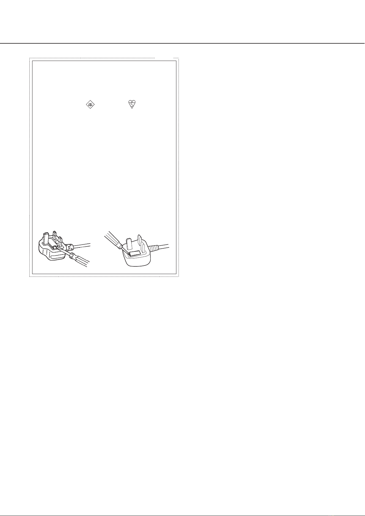
WARNING:
• This apparatus must be earthed.
• Apparatus shall be connected to a main socket outlet with a
protective earthing connection.
• The mains plug or an appliance coupler shall remain readily
operable.
• To prevent fire or electric shock hazard, do not expose this
apparatus to rain or moisture.
• The apparatus should not be exposed to dripping or splash-
ing and that no objects filled with liquids, such as vases,
should be placed on the apparatus.
• All work related to the installation of this product should be
made by qualified service personnel or system installers.
• For PERMANENTLY CONNECTED APPARATUS provided nei-
ther with an all-pole MAINS SWITCH nor an all-all pole circuit
breaker, the installation shall be carried out in accordance
with all applicable installation rules.
• The connections should comply with local electrical code.
CAN ICES-3(A)/NMB-3(A)
For Canada
The model number and serial number of this product may
be found on the surface of the unit.
You should note the model number and serial number of
this unit in the space provided and retain this book as a
permanent record of your purchase to aid identification in
the event of theft.
Model No.
Serial No.
For U.S.A.
NOTE: This equipment has been tested and found to com-
ply with the limits for a Class A digital device, pursuant to
Part 15 of the FCC Rules. These limits are designed to
provide reasonable protection against harmful interference
when the equipment is operated in a commercial environ-
ment. This equipment generates, uses, and can radiate
radio frequency energy and, if not installed and used in
accordance with the instruction manual, may cause harm-
ful interference to radio communications.
Operation of this equipment in a residential area is likely to
cause harmful interference in which case the user will be
required to correct the interference at his own expense.
FCC Caution: To assure continued compliance, (example -
use only shielded interface cables when connecting to
computer or peripheral devices). Any changes or modifi-
cations not expressly approved by the party responsible
for compliance could void the user's authority to operate
this equipment.
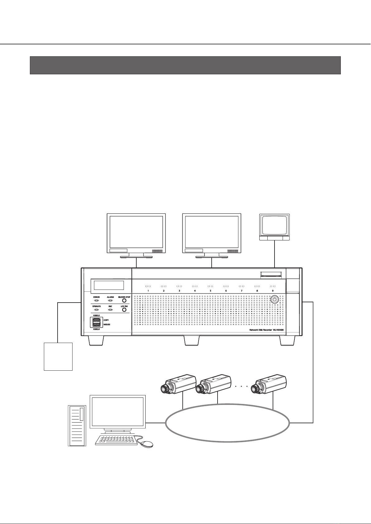
For U.S.A.
UL listed model No.:
WJ-NX400K
For U.S. and Canada:
WJ-NX400K
For Europe and other countries:
WJ-NX400K/G, WJ-NX400K/GJ
Safety Information
In English: “The equipment must be connected to an earthed
mains socket-outlet”.
In Danish: “Apparatets stikprop skal tilsluttes en stikkontakt
med jord, som giver forbindelse til stikproppens jord”.
In Finnish: “Laite on liitettävä suojakoskettimilla varustettuun
pistorasiaan”.
In Norwegian: “Apparatet må tilkoples jordet stikkontakt”.
In Swedish: “Apparaten skall anslutas till jordat uttag”.
For Denmark, Finland, Norway, Sweden
: Alternating current symbol