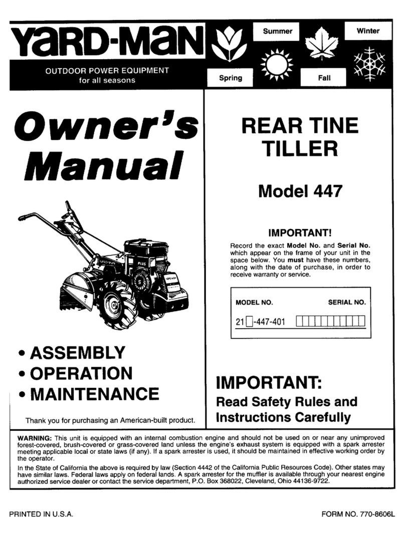
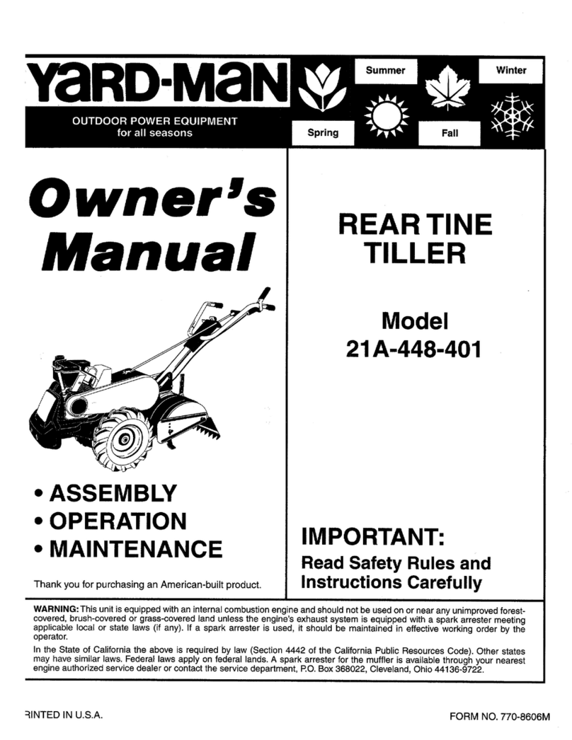
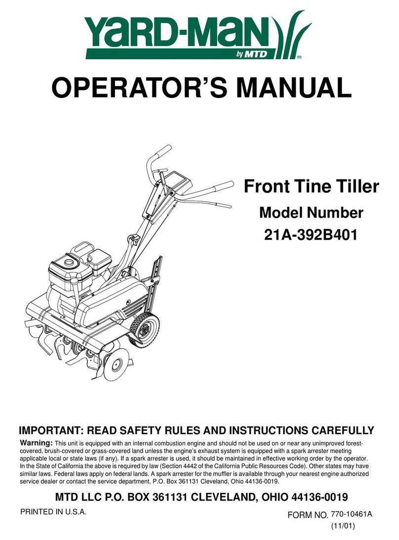
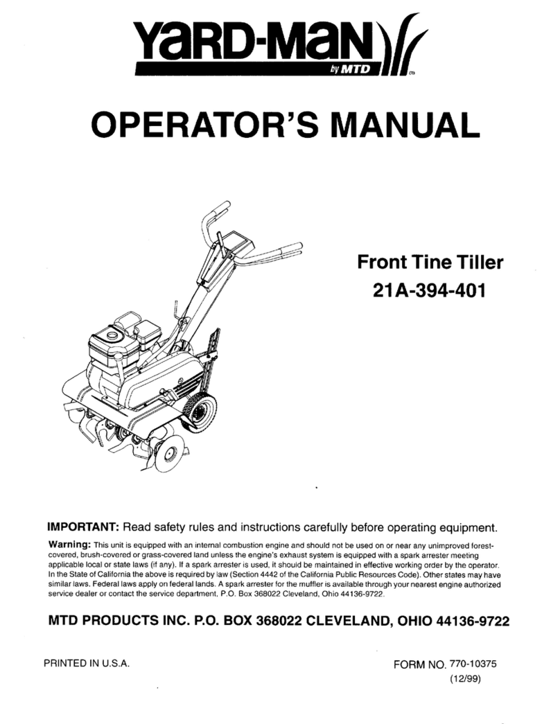
Yard-Man 5010-1 3 H.P. Operation manual

MODEL
5010-1 3 H.P.
5020.1 4 H.P.S030~1
5 H~P~
STOCK NO.
08.28-08':'48~08-28-
EARTH:8.1RDTfLLERS
,
r'.,
-'" ,
;:f,..t.(.)',,~."":"~/U~(.':
'""/C-.~ ~ ~
"iC~:;!;
..,(" -I " /'
I " '
YAR-D ':' MAN CO.
p, O. BOX 36940
,CLEVELAND)OHIO 44136
PRINTEO IN U.S.A.
300,1400-8
50C-4

RUtES---F'OR'S:AF'EO'PERAnO'N
Yo\)r EARTHBI AD Tiller "isa precision piece of tilling equipment, engineering skill andexperiencehavebeencombined tq prpvide
the L/ltima~fJ'in ae~f;!.tyandetficiency. However, aswj~h any type of power equipment. carelessnf!sSor::erroron th~par' of the oper~t.
or can result in injury, 'There.fo~e.exercis~e~treme c~6t.iQnatall times.
1.
2.
3.4.6.6.7.$,
9.
iO.
1'.12.
KNOW YOUR MA~H.lNe'R'&ad, ~he Owner's Manual carefully -learn how
to operate your EAJ:'I;THBIRO pr~perly and haw to stop quickly, ,
MAKE SURE THE AREA tS CLE;AR of bottles. stones. wire and:ptl1er
, ' " ,
haz~rdous items before t~'j\ng. Such items ,~redangerous to both t~e oper~tqr
a/ld machine, :'
ADD FUEL before $(arting ~ri9ine ". never ~h8n ei'lgine is hut or (\,Inning.
Replace fuel tank cap:securely. " ' '
ALWAYS STOP ENGINE ~f1d discorynect sparki:l"u9 wire be'r~re atte~Ptil:l9
any repairs or adjustMents. ',' "
DIS~NGAGE ALL CLvtCHES:an~ shift ;n~o neutral bef91'6' ~tarting'.m'otQr.
Keep hands, feet and cjt)tl'\iri9aw~y from power cjrlVt:nparts,
';,' ", , '
START THE ENGINE tAREF~t:LV A!W8Y:Ss~and at side of maCl:1lne: Do
not operate engine indoor$witlio~~pioper ve~.t:ila~i~n:,-, ,: " :,
DISENGAGE POWER AND SrOPMOTO(:t'before re:m~v,inQ'Qbstatles.-Qr when
leaving oPfJrQting Position. ' ,',-'
" .' :,
DO NOT ALLOW MINO~S toopera:t~ ,m:achirie urile:5$~tiorou9hJV iostructed
and properly supeNised, ": c,
, " ," " , " , '
KEEP CHILDREN AND PETS ~W~Y,f~m~Qtati~i3 f,ft'tes. Keep ~safedi~:t~hC~
away from fences with totatingtiryes; ,
..
NEveA WeAR SANDALS or open tO$d shoes when operat;n9'm~chin~. ':: '
;" '
ADJUST DEP1'H BAR for de$irad tilling depth before startinQ:engrne.
EXERCISE CAUTION 10 avoid slrpping or falling when op~r~ting machine.
t

SUG'GESTI,p'NS FOR MORE 'EFF1CIENT, AN:O MAINTENANCE-
, ::, FREE OPERAr.JON'
GrNERAl TILLING:
2.
3.4,5.
Keep area to be tilled cl.t!ared of vines. glass, wire, and stones. ' ..': ':' ';
'" .-, ,
Always start engine with machine on level surface with master' clutch disengaged, Aftecr: starting, let engine warm up several
mInutes at slow speed before:starting ,to;till. : " '-: ,,::',
,
AlwaY5 preset d~pth bar i(1to ti)e grqund befot~en9~g1ti~"m~st~r:~IL!tch~9ntrOI.: :,' c'..' ' ,
When tilling, run machine at throttl~ ~~ti(l)g'~esi 'su~i~d ~,o~ro,\Jnd:.corldjtion~.::Alwavs lower t.he tines "slowly" in to the soil,
hold\I'I:9 ba~1<on '\he hand\&s until th~ d~r~d:'ill\~9',d~~ ,i~ ieath~: the~ alJ~w the:til{~~" tti:'move forward slowly using the
depth 'bar drag setting, ' :", '
,
In hard sod or on rough ground it is u5ualJy ~asier to ma-inUiri.' a $tr,ight forward motion with a slight movement of the
handlt:!1!from side to side, When making the first 1;ut1hi9ugh ~I'I;a,.~a the tiller will track ..Sctraight line. but wh.erl cuttif\9
the second path the~ witl be a tendency to mol/e' 1owardsthe iQ6se: soil. Moving the handle from side to side Will aid in
followrng the edge of the first cut in making a wide str:aigh.t tilled area. After's )ittl~practjceprQfjcjency in the op~ration of
, .' .-'. '.. " " ,
the tlll~r u'n-deraH'~Qnd.itjoj'\sw-llibe Qai~ed: ", '.
MAINTEHAHC£:
You, EA~TH8\,RD '\jkeiJ1.1"math\\1e~w~I'h!:I'ovingparts, f'!)U$treceivec~re and mamt,ef)Qnce,The following tip$. it u~~d,.."iillcon.
itibute manytrouble,1ree:~ou(sto yOur macryine,
1, CneCl<ojl ;t~,vel~eqiJe'~tIY. 61'slIerv: 5;hours ot use,Wher'lchanging oil, ma~e sure dirt and debris is cleaned from oil drain
,araabttore:temavihQO!' P\u.9:/ ':
2, Keep tines ~nd 1:lhespoois/~1~ar: '
" " ,
:i: Chec~:all nuts, bolts ~n9sc~e~so!:c~sjori!l.liyfor tightnessto be suremachineisin QoOddperatingcondition.
.' , " ,
4, Tt,e mat-hineis pta.llibr,iccitedat ~r~ f~c~bfy:Howev~;! lubrication With'eachusage~i11prolong 11f6of wor~ing pa.rts.
5. If you are.9oin~to store your EARTHBIRD1or atl¥ length of time (30 days or longer) it is important that the follOw.
Ing stepsbe takel1. a, Drain the gas tank and carburetor, Allow t,heengjne to fUrl out of gas.g,!~oline
left'in the engine will leave 9ul!1/deposit~ in.th'ei:srburetor ~nd gas tank.
b. Cle:a~en~i(\e o~ all f?~ej~f1 ~~tttr,
c. LUbi'ic8te,cYl(n~er by removing the sparkpJlJg a:nd pol,Jring one oun~e ofctean
lubricating o-il through t:h~ s~arl:Cplugho,le into the cylinder. Cr~nk engine sioWly
to spreadoil a~Qtepl:acesparkp1ug,
6.
7.
The tf.an:smissiqn;is p~~.lubricated, Every 10;15 hours of bperation chec!<the oil .Ievel.by remQvingthe oil levelplug. UseSAE
~Ciextta duty tral'l~missionoil to fill if level ISbelow plug openitlY. Changeoifevery 25 hours.
Thebeit t~nslbri'js -q!:ljustable,The tensioning of belt should be cht?ckedevery 5-10 hours of operation. Refer to adjustmentss~ion;for
resettiilg,
8; J~st.asvour ~utQmQbi\~n'e'eq~protessiOn6\mechanica~ma;ntenal'lcefrom time totime, ~odoesyour aircooled engine. A yearly
t~f.e:'l.Ip'andGt}ec.1<~1aqM~I;~:iedservicece;nterisrecommended to avoid breakd<;Jwns-and u~n!1cess~rYdejays dt,iTingthe tilling
seasol'l, .' ..
3

UN,'';(111 6 AND SiT.UP
1, Be sure carton is right side up. cut end panels out and
fold flat on flo~r '.Re~Ql/e i(!ner pack and roll unit out 9f
carton,: '
2. Assemblethe right and left handle tubes to the unit with
the rigl1t and left hatJdJesocket caps and bO;Jts.00 not
tigh'en.'
3. AsSemblethe handle panel as$emblyover the right and
lefthilr'ldle tubes :andsecure with four slotted round head
bolts ~~d lock nUts. Tighten 8111;hebolt$ on th~ handle
assembly. Placeth.~h~dl~ grips ov~r:th~ end~o(the hand)e
tubes.
4, Place;one,end af ~e IT)ast~rclutch .rodtt)roughtt:ie,hol~
at the bo~tomof the masterclutch con1:roland the otherend
thr9ugb the hole in '!he tlipper heat the end of the left
handlE!tube and $ecur¥.with the two cotter pins.
5, The tilling width is,ass~mbl~dfot 22" as,shippeq. For
11" tilling width r&move hair-pin and clevis pin arid piJll
Qutsrd~:SpoolAS$smt;Jliesfr:6m stiaft;Replace clevispina!'ld
hair-pin thru in5id~Spool Assembliesand Shaft,
6. Attath the depth bat releas~handle to tbehandJei near
the right handle grip with 8'slC)tte~headscr~w ~rid nut.
Attach the upper dep'thbeT' relebse rod to the handle by
hooking the loop~ end th~Qughthe ~aton the handle from
the outside, Attach the opposite end down through the
round h?le In t~e depth bar pivot plate, SecL)rewitt1 i
cotter pJn. Atta<J!:1the double bend enQ of ".thelower trip
rod down through the slotted hole in the p.ivot plate:
S~cure ~)th ~ wa~her andc9tter pin.. Thread~~f! Adjust;
ment Link on t:he opposite end and ad;ustto align With
hole in .Oepth Bar La~ch.Secure w.ith a cotter pm. Che9K
operat\on of Oep'th Bi)t ReleaseHandl& aft~r:attaching rods,
With Depth ~at Release Hanc!le@!ithe wuy uP. Depth B~r
latch should release. for faiture to relea~. re-adjust the
Adju$1ment ~jnk,
7. Attach the depth ~r Into the bracket at the rear of the
tiller frame using the short clevis p\n through one of the
holes m the 'bar, s~cur'ingloViththe hair pin cotter. Use the
pointed end of the d~Pth bar in the ground except when
~h~IoIseof 1hefurrow plowIS~esired,

BlfGR:£stARTlHG£"61"1.
1. Fill the fuel tank With ~ good ,grade of regular 9a.sollne.
Do not mix oil with gasoline.
2. Plac~ m~chine on 9 level surface, Remove oil filler cap
and fill cr~n~~s!'J'..""ith909(;j quality geterger'lt..oit. Above
32~F use :SAE .~O~;,~el~w 32°;:yse SAE l()W. Fill t6 over:
f.ll::i~i!iga:~d r~p.lace~ap; : "
3. b~rir:,g Irijti~(:iBr:eak.in.',': p~riO'q, ;W,e off lel/el should
be ch~ck~9 oftery. ~ ; -': "~4.
Che£1<.Oil 'I$y:&1evef:Y five {5Y,op~rat!n~ 'hours 9r eachtime,I'rI&(i"'jn~
i$ usl:id. ,
ST,AtT:I:NG
"NtINE
Shift the master, clut~h, C4h:t;rolto ,th'e neutral position.
Move the speed c::ontrQI-l~ve1'to 'fUI'1chok~ posi'tiQr1\Start
the engine by -pJllih9 tapidly 91'1~h~,r~cpil;starter rciee- A$
the engine ~t~rt~ ~1id'begins towariri up gradually teturn
the c:ontroi lev,rt<i1hede;sir~~ tp~~~;po~ition,
If the engin~ shouJd-fa:il ~o ~t_~;:rff:er to your :engine
Instruct{()" Manual; ..
5TOP";'-6E"GJN'f
To
S~()P:the'~~Sin:e m~\ie the:spee~ cpntrC1tJevert(>thestOI?
po~i~ion:.'YhQsparkplugwir~ mii~alsobererno,vE!dto
preventaccid~ntal s:rartingwhile llnattended.
O'£I'"10N
OF CONTROLS
MASTIICLUT(M(0"TI01
The
maSter clutch control is'\oc~red '-on the handle panel
assembly a~d is used to engage,th~:f~rward and reverse
belt idlers. Move ,t~e clutch :con~r9Ifu~ward tP engagetheforward
,belt Idle/'"Pul1the"clutch~cir'ltr~1'h:ick to thecel:'ter
position: for neutral. Pull the c(uttthcontroj back and:hold
,
for reverse. Operat~ t!ie 'ciutcti ,~ol1trQIseveraltimes'until
the neutral poslt!on' cal'jbe:~asjlydetermined for the cOf)~rol
'- "
should always be in this ;Pos1tion befo~estartil:'lg ~,rygine.
DEPTH 8AR
Before tilling lock depth bar in vertical position, al,ds~$ke
imosoil.
Adjust bar depth'to suit soil col:lditions, and depth of
tilling.
When reversin9 for tr~nching, back filling or tine clea-n(ng,t.he
depth bar sho~ld be in the vertical !ock~d ppsj~jon,
The release liiifldl~u:nfQCkS the depth :D13rfor transporting
or reversingwhen required.
5

'~lUS
fliNTS:' ' '. ..
NOTE: Make all adju$tment~ with engine turned off and
wire removed ~rom the sparkplug, (Fastenwire to ~Ylinder
head ~t t$Q$'t1" Qwayfrom spirkpl\J9.1
tEll aIPlA«MINT .NO .":I;:~":
IDlIR WHEE.lADJUS1MINT'
CAUTION: For belt adjustment the engine :;hQuld be
stoppedand tile sPIlrl<p!ugwire 'removed.
Aftl'lf themac~Jne has beenQperated a short til'l1elt may
be riece~ry to re~djust.the idlers for proper bett ,~~n$i()n,
The fOlI6wif19;'st~J>sshould also be carefully f~Jlowed
when installii1Y the replacerT)en~b~lts OJ adju$ting belt
ten$ion.
FORWARD OR1VE 8ELT':- :.-
1, Move the master clutch' ~o.nt'rolfQtpeneutra! p,6sition.
2. Rerno~e the b~It:~~ard t;irac1<~tfor' ~&It repla,cement
~nlYAdiust the jdlet~n~)i(T~tep~ Qf 8pproxima'f0!V 1/4
inch and mamtilin $Oi1'l:e,~18Ckif) the belt \(\' the :rieutral
position. If the b~lt f~jl$ to rele~sePf9perly in ne~tr81
adjust the idler wh~el away fr<lmthe beft: After positi9ning
the i~ler piJlley relocate the forward belt restrictor lo~at\ng
tab In the idler str~p:slot..AI$o, check theclearancl;' be1ween
the belt and thq belt restrictor p!il$ (in the forwardr\.Jnning
position), pins should clear belt approximately ;/1&~hen
b~'Itguard bracket ISre.iJ1stalledor in piace,
REVERSE:DRIVE BELT
Adjust this belt in a similar manner asthe forward drive
belt, bv loQser\rrygthe bolt t'!olding the revers!;!idler pulley
in pos:ition and movtng it up toward the belt to tj~hten.
! Q c~i?k the ~ttiNgfot' ~he'proper a:mQuntof slack:l'n the
belt move the master cll.!tch control to t/:1efQTwardrunning
p~~itiQn (with the engine stpppedl and position the belt an.
to the rim of the idler pulley. Move the 'idler up with the
belt In thiS:po$i~iorr, unti'f the belt istight and tlght~h the
idler bolt, Then recpO~ttiont~e belt i()the ~enterof the idler
pu~ley,
NOTE: The fiat side of the reverse belt shoultj always be
01\ the inside. RetlJl'I"I'the clutch cor\~rol to the !)~utral
positron ar\~ c:heckthe position of the reverse idj~r b~lt
restrlctor. Th;~ :!:f!strictorshould be again~tt~e rever~~belt
I:t> allow the:bel~, to only sl.i9b~ly tQuct:t the :e~gine:
drive pulley; bt:it, sj'lciUld clear th~ belt w!th th~ riJutch
control pulled b~k in rev~rsepositib'n. ,:c ,
fJNE WJDfN ADJUSTMitff:":,:', -.
The tine spool a:ssemblie$c:canbJadjusted t9,,11:"of'22"
tiliing wjdth~, Refer to Unpacking ari~ $e~ Up ~ecti()n for
de.t'ails. Tilling width up to ~2~';jsitv~llable.' With'~ptional
fine extension spoofaS$~mblies.
DEPTH8AI ADJUSTMENT
To ra\~ pr \'ower'the dsp'th bar remove the hair pin cotter
and clevis pin and move up or down. The depth bar setting
helps control the depth of till ~nd amount of drag re$i$1ing
th~pu"i-n9 ~~tior:,~f the t:Qta~ingtines..
6

.lV..JCATION
CH'AMGINGtN&IN} 0:1('
Drain oil when engineis warm. ~emove oil drain plug and
allow oi! to drain completely. Replat;e drQin plug and
tighten securely.
s~ engine ~anual fpt. cQmplete englr'!e l.ubric8tion and
~rVjce instructions" ;.
(U'RJCAT:~N'POINtS
,l,.UBRICATE THE PARTS,PERIODICALLY
AS,:llL~STRATED
The following points are to be lubricated every five hour~
of operation with SAE 20 weight light duty oil, uniess
otherwise noted,
1, Clutch flipper,
2, Reverse arm.
3. Depth bar linkage.
4. Wheel$
5. Masterclutch control.
*6. Ge;arhousit19.
.Before operating the tiller. check the oil level in the gear
case by removing the ojl levelplug. With the tiller on a level
surface or sTightly til~fJ.dback, the oil level should be (it
least to this o.penit;gor above. Every 10.15 hours checkand
maintain this oil level using. a heavyduty gear oil, such as
GX-90 dr Type 47 04tboard Motor Oil (90 weight~. Drain
the gearcaseand refill every 25 hours,To drain the oi1from
th~ gear case, first dr~in the oil and gas from the engine.
Then removethe drait1Plugand tilt the unit forward.
NOTE: The gear case$hould not i:!efilled completely full.
AFTER BREAK,;IN PERIOD. {FIRST 3 TO 4 HOURS OF
OPERATION} CHECK ALL BOLTS AND NUTS FDA
TIGHTNESS.
'7


PARTS I.IST
Your Tiller isRight Hand IA.H.t or Left Hand(L,H.I as You Operate Machine.
NOTE: Unlessothe,wis~ specified parts listed are usedon all Models.
REF
NO.
I
,
:2
2
PART No.
40~:!.3
42050
403~5
4;20..49
61832
61836
61818
61834
61838
61829
6183::1
61837
618~1
6'835
1$41-5
1546.29
15Q9-91
1542-8
41:;}'42
1632.142
40299
t652-90
~O1.135
0115.33-
42340
40060
42122
40048
40164
40163
40023
20644
20612
40099
1547.42-
20301
40250
1663.23
40305
4Q~96
40149
, 42:3$0
401$~
501;139
4~1'pO
41133
403'18
61814
1534.20
40303
4Qo25
40317
42;3;51
4Q893
42331
16'01).439
1601).440
'606-441
22:517
4~2!49
42250
42251
6t839
61841
161t3.317
164~.42
42334
QTY
B
8
8
8
T
,
2
,
1
2
,
,
1
1
3
2
T6
16
16
T
2
2
1
1
1
1
2
1
1
2
2
1
1
5
5
6
7
8
A
10
11
12
13
1&
16
17
18
19
20
21
22
23
24
25
26
27
28
29.
30
313.2
33
34
~5
36.
3'1
38
39
40
41
42
43
44
45
46
47
48
49
50
50
50
51
62
52
S2
53
53
54
55
56
1
1
2
1
2
1
8
2
12
5
1
OE~CRIP-rtON
Tine, 6010 (L,H,) 5/,6x 1~1/4 It 14" dia. (5020.1.5030-1 only)
Tine, Bol6 \L.H.j'13/6.4 x 1:1/4 x 14" dia (5010.1 only)
Til~e, BOlo (R.H.I 5/'G'~'1,'f4'11 14" die, 15020-1,5030-1 only)
Tine, BOlO !A,ti:f '.13164X 1.1(4 x 14" dia. (5010-1 only)
Assy, SpoOl, Outside~/Tln_s'iL,H,1 (5010-1 o'nlvt
Assv., Spool. OutsidewfTir)es:ll.H.) (5020.1.5030-1 onlv)
Assy..SpObl, O'J!side: :'
Assy.,SpOOI,ln$idew/TinesiL,H'.) (50'0.1 only>
A,SSy', Spool, Insidew/Tinos !L,H.) (6020-1.5030.' only)
AUy.. Spool. Inside
AMY.. S"OOI,I"$;<11o wjTines l~H.J (5010.1 only)
A$SY.,SpoQJ, Insi~ w/Tinec' (A.H.) (6Q20.1, 50.30-1 only)
A$Sy,'SpOOI;O\.ltside w/Tines (A,H,) 15010-' ()nly)
A$$V.,SJ)oOI, Outside w/Tines (R.til (5020-1,5030-' ontv~
HaIrpIn totter, 3/;12 die,
P\N;Clevis, 3/8 dia )(2"
Bolt; Hex Head; ~/a-16 It,., /4
Lockw.~er, 3/8 ISptlng Type)
Ntj!, ttex {ES\..OK)3/~:;6
Shaft, Tine, 1" dia
Oil SRel, Do\.lble Lip
Se~ring, Nefl9le. "'" 1-1/4 x 1" L.'
G~ar H!>usi~g
AS$Y., Transmission, Cumplete
Plu9, Pipe. 1/8 NPT.F' (Spetiel Vent,d}
PII!~, Pipe, 1/4 NPrf'
Nut,tie" Flexlock, ThIn, 5/16-18
P,in,Spring, 1/4 die. x 1"
Bearing, Thrust
Washer, Thrust
Bearing, Ball
Worm, 3T. (RH:I
WormGear,~8T. (R.H,)
Spacer, Worm
Pin, Grooved. 5/16 die. ~ 2"
Shaft, Pullev
Pin, Spring, 1/8dta. 1\3/8
Gasket, Geer Housing
Bolt, Hex H$ad; 5116-18 x 1.1/2 (NY LOCK)
Lid, Gear HousIng (includes Bushing Aef, No. 4p')
LOCkw~er" 5/16
Bo"t, Hex Head ((1rade 5) 5/16-18 x 4"
Nut, Hax lack (2.w~y) 5{16-18
Bolt, Hex He.d, 5/16-18 !t2"
Bolt. Carriage. 5/1&18 x 3/4
8~lt,"Cartiag., 5i1~.i8)( 1"
Spring, Exten,ioh
Assy., enQin~ 8,se
Nut, Hex, 5/1£':18 ",:'
!:"xtension $iock
Seal,OII
6ushiflQ, Qilltt, .191 ".817 x ;.1/8'"
Bolt, Hex Head-{Gr8d~ ~t 5/1ti~18 x 1~112
Bolt; Hex Head,5/16.18 ~ 1.5/8
Decal, Tine Shield C
Det;81, Mod~1 No. (5Q10-1 only)
Decal, Mod~.tNo~ (5020.10;11fyl :' ,
D~I.. Model 'No. (503~.1 onlyl :
Cover, Tine Shield
Er'lginl:;3 H:P.(6010.1 anivl
/ET)gine, 4 H.P,(50~9-1 q"WI
Engil'le. 5 HP.i$O3Q.1 only!
A.ssy., Pulley Colier Support ~racket(502o.1. 5030-' only)
A5$V, Pulley COll~!' Bracket ('5010-1 only)
Decal, Belt Adjustment Warning
Knob, Throttle Cohtrtll (5020-1.5030-' onlyl
Decal, Engine {5010., only)
10

PAl'S LIST
YourTilleri$RightHand(A.H.)or left Handtl.H.) asYouOperauMachint.
NOTE: Unlessot!1erwi,e specified P8Y:tslisted ate usedon all Models.
R~F,
NO.
56
56
57
58
59
6t)
6'
62
63
64
65
66
67
68
69
70
11
72
73
14
75
16-
71
76
79
80
81
82
83
84
86
86
87
68
~9
90
91
92
93
94
95
96
97
98
99
100
101
102
103
104
105
1Q6
107
108
109
110
111
112
113
114
"5
116
117
118
119
120
PART NO.
4233,5
42336
401,$2
1616,280
264341
2610-14
1552.12
2706.25
162S:25
1650'36
40035
6167j
40324
21410
40302
4029~
11&8..45
1513-91
60312
4005'2
6030$
151
42373
20500
40319
1626-69
20142
2'2446
1161
1626-72
20265
40041
4OU3~
2153:'
40201
40032
'509,31
22568
60319
S'84tJ
1529':39
60199
15Q9~112
20100
42238
42239
22520
16$3~15
1625-27
1539.24
4()148
603:02
2251'8
40225
60n,
40211
400e;5
42210
422Q1
422)1
6115~
40286
4Q.120
42332-
42330
61822
QTV.
1
,
4
1
1
,
1
1
1
10
1
1
4
4
2
,
~
1
3
1
2
6
f
1
,
2
1
2
1
1
1
1
1
1
1
,
,
1
,
1
1
Z
2
1
1
1
1
,
,2
1
1
5
f
2
5
1
1
2
1
2
2
1
1
,
DEscRIPTION
Decal, El1gine15020-1 OI1IV)
Decal, C ngine 1$030.1 Ol1lyl
atilt, Hex Head, 5/16.18)( 1-1/2
Decal, Air ClfJaner label (5010.1 onlVI
Knob, Throttle Control (5010-1 only)
Bu$hing, Adapter (FiltarJ (S01Q-1 only)
Wasner, Wave, 1.46~ x 1-82)( .015 (6010-1 onlyl
Lel/er, TtJrottle ConrrQI (5010.1 onl'",)
Link, Throttle ConlrQI (5010-1 onlyl
Ring, Ret.ining,1~3/B (6010-1 Orlly)
Pih, Cotter, 1/8)( 1"
AsSY., Reverse Arm Retainer Washer
Spring, Torsion
Washer, Cup
Washer, Felt, 5/8 )C1-1/4 x 1/4
Wheel, 101\ 1.75 x 5/8
Au",., Frame
601t. Shoulder (Special)
Assv.. Depttl ear Lock Torlgue
Piry, Spring, 5/16 dIll. ~ 1.t/2
A5SV, Depth e.r Gllide
Wilsher. Flal SI"J, .320 x 3/4)( 16 Ga.
NU1. H~x lock (ESNA} 6/16-18
Depth Bar
Pin, Clevis, 3/~ dla. >I1-1/8
Pulley, Idler w/H...b
Washer, Idler Pullev
Bracket, 6elt Restrictor
$crQw, Set. 5/16..18)( 3/8
Pu1ley: engin. (po\Jblel
Key, Pulley, 3(16 sq. 1\ 1.1/2 L-
8elt,4t.-4001Spec;ial)
"V" Pulley
Bracket, Belt Restrictor (Reyerse)
Belt, 4L.450 (SPecial~
Pullev, Flat
6olt, ~e~ He~. 5/16-18 x 5/8
~racket, Belt Guide
Auy., Clutch lOCk,Out
AS$y" Reyef5e Arm
Bolt, Carri~ (Sh. Sq, Nacl<l 5/16 x 2"
AsSV.,ldlerPutley (Flatl
BOlt, Hel< H~eQ(Grade 5) 5/16.18 )( 2"
Cap, Handle Socket
H'Indie (RH.I
Handle (L..H.I
ROd, Clutch
ROd, Lower TriP
Link, Rod AdJu$tment, 6/16.18 T
Pu~hNut. 5/16
Washer, Wrought, 5/16
Auv., Trip Pla1e
Rod, Upper Trip
S~"ew, Rou"d Head Stove, 1/4.20 x 1-3/4
Auy., Trip Handle
Grip, Handle. 1.1/4
NlAt, Hex NylOck, 1/4.20
SQlt, Hex Head ($petial) 5/16.18)( 1-3:/4
Tube, Spirt, 1~/32 O.D. x 16 Ga. x 118
Washer, SpecIal Spring
Assy., Clutcl\ Harldle
Handle Pin
Cap, Ptettic 1White)
~cal. Shift (Handle PanelJ
Decal, Handle Panel
A$SV.. Handle Panei
This manual suits for next models
5
Table of contents
Other Yard-Man Tiller manuals

Yard-Man
Yard-Man 21A-448-401 User manual

Yard-Man
Yard-Man RT65 User manual

Yard-Man
Yard-Man 21A-394-401 User manual

Yard-Man
Yard-Man 21756-9 User manual

Yard-Man
Yard-Man 21A-144R401 User manual

Yard-Man
Yard-Man 770-8606A User manual

Yard-Man
Yard-Man 769-01534 User manual

Yard-Man
Yard-Man 447 User manual

Yard-Man
Yard-Man 454 User manual

Yard-Man
Yard-Man YM141 User manual