YARMEE Digital IR User manual

Installation and Operating Manual
R
Digital IR Language Distribution System
V1-201410

1
[Table of Contents]
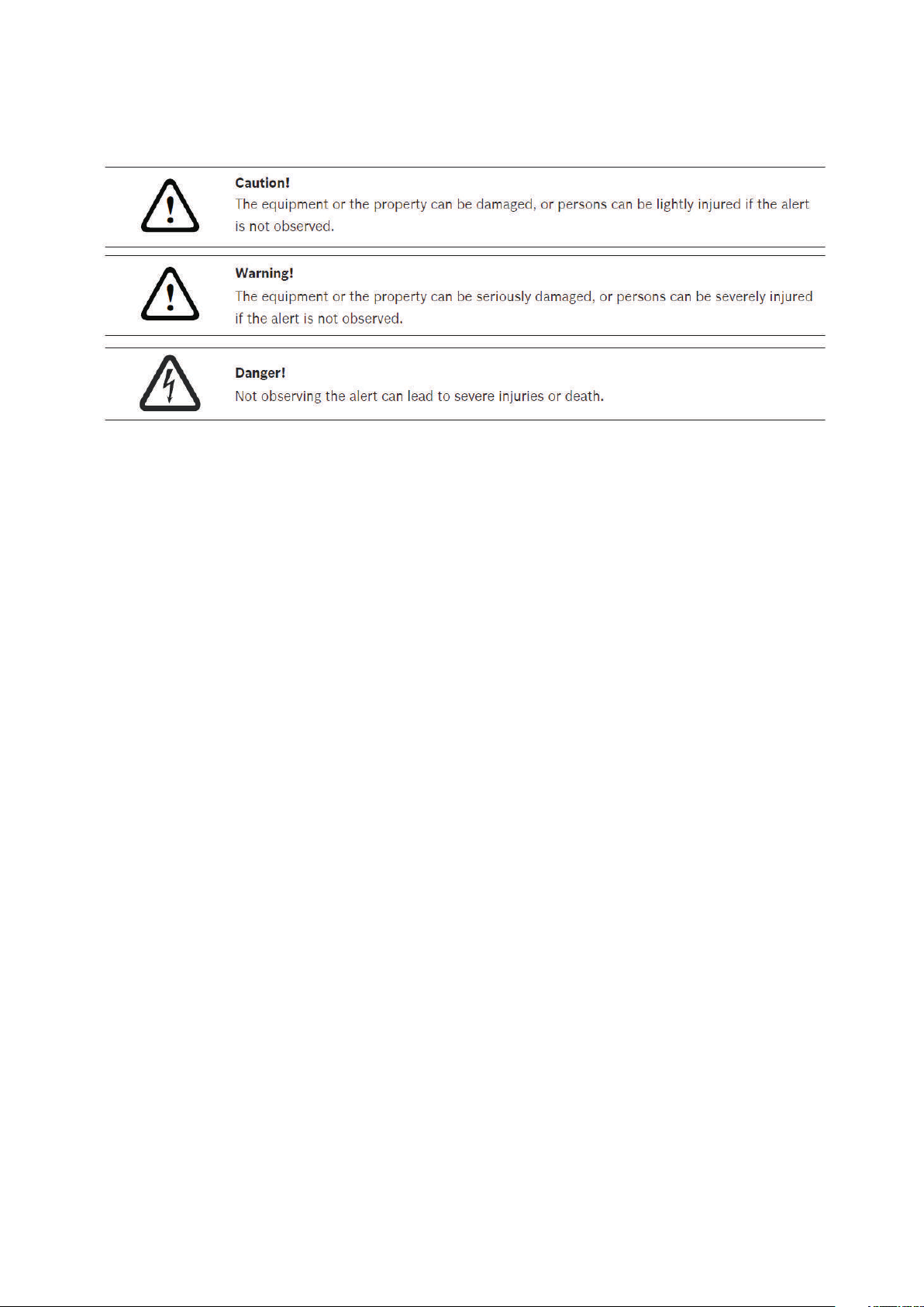
Important Safety Instructions---------------------------------------------------------------------------------------------------3
1. Overview-----------------------------------------------------------------------------------------------------------------------5
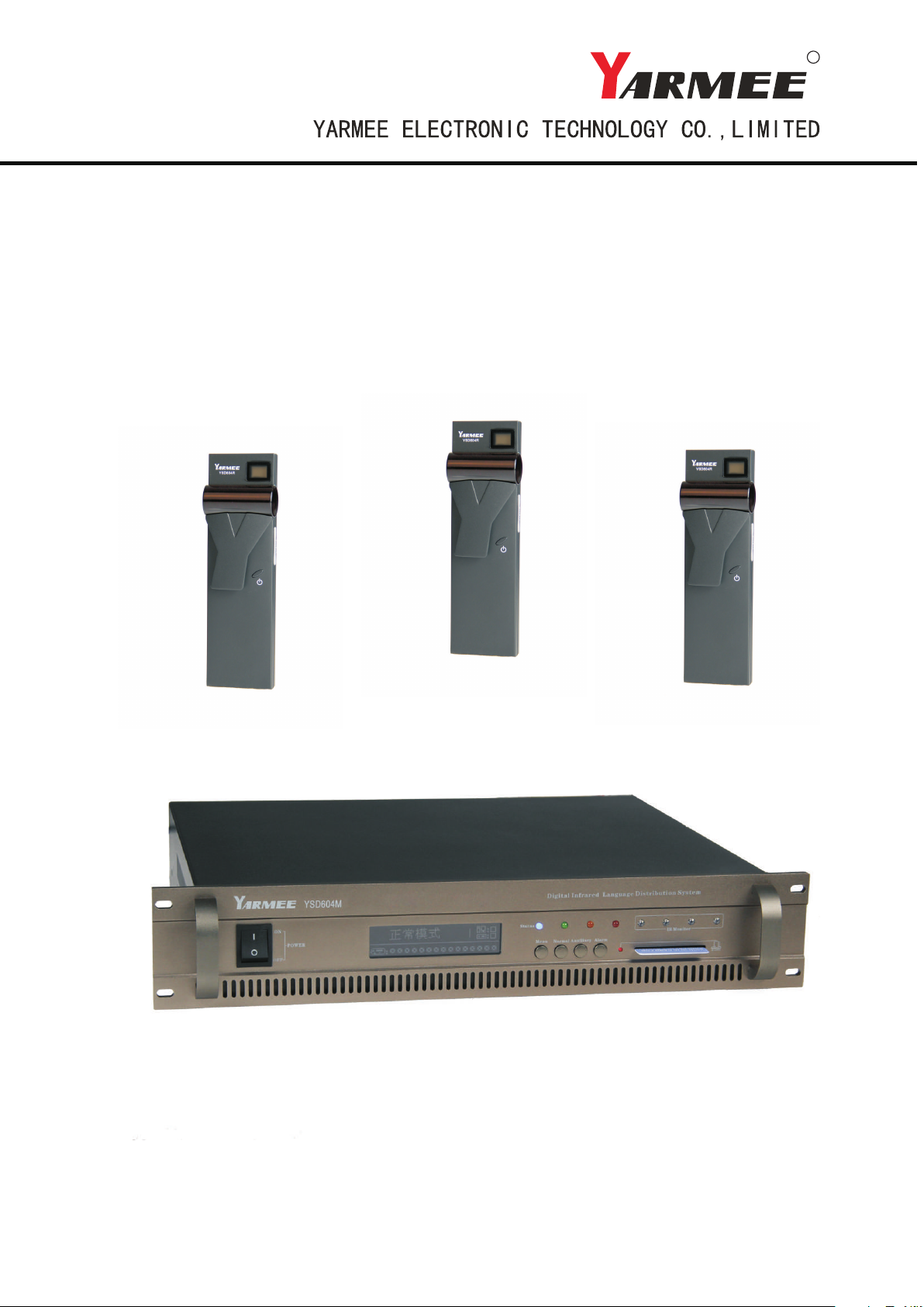
1.1 Digital Infrared transmitter --------------------------------------------------------------------------------------------6
1.1.1 Picture of the actual object ------------------------------------------------------------------------------------------- -6
1.1.2 Features of digital infrared transmitter------------------------------------------------------------------------------6
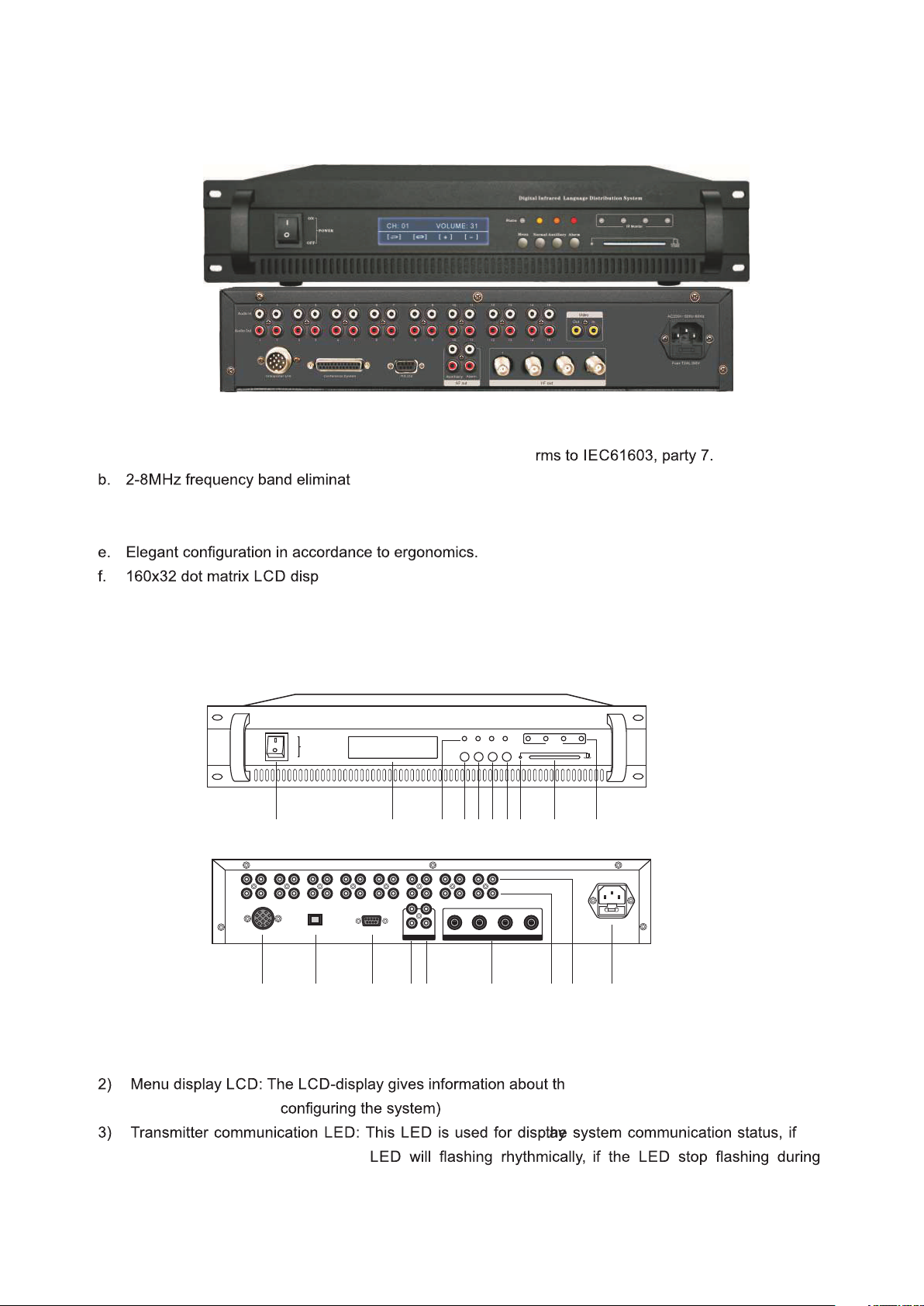
1.1.3 Schematic diagram of digital infrared transmitter----------------------------------------------------------------6
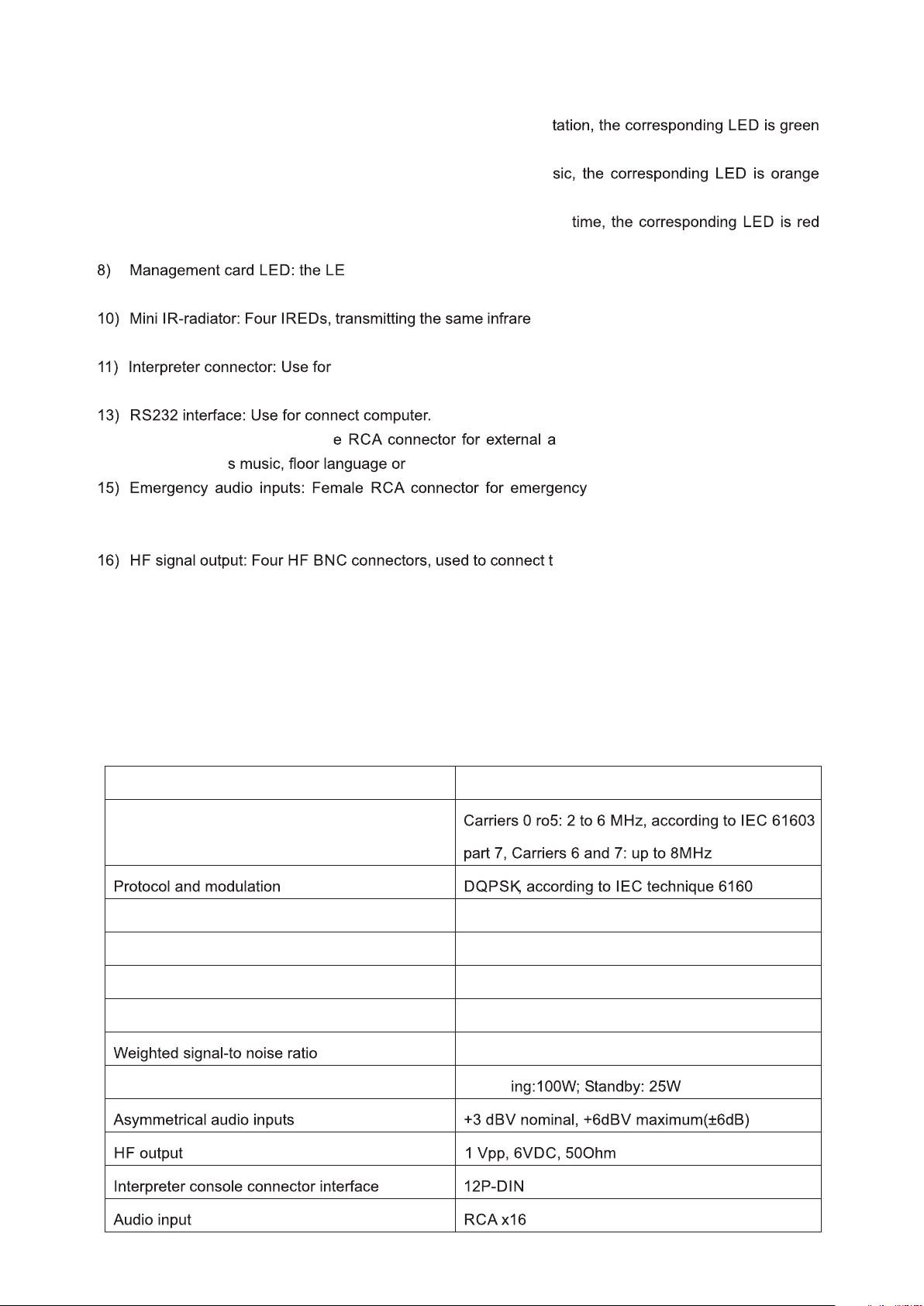
1.1.4 Parameter of infrared transmitter------------------------------------------------------------------------------------7
1.2 Digital infrared radiator-------------------------------------------------------------------------------------------------8
1.2.1 Picture of the actual object ------------------------------------------------------------------------------------------- -8
1.2.2 Features of infrared radiator ------------------------------------------------------------------------------------------8
1.2.3 Schematic diagram of infrared radiator ----------------------------------------------------------------------------8
1.2.4 Parameter of infrared radiator ----------------------------------------------------------------------------------------9
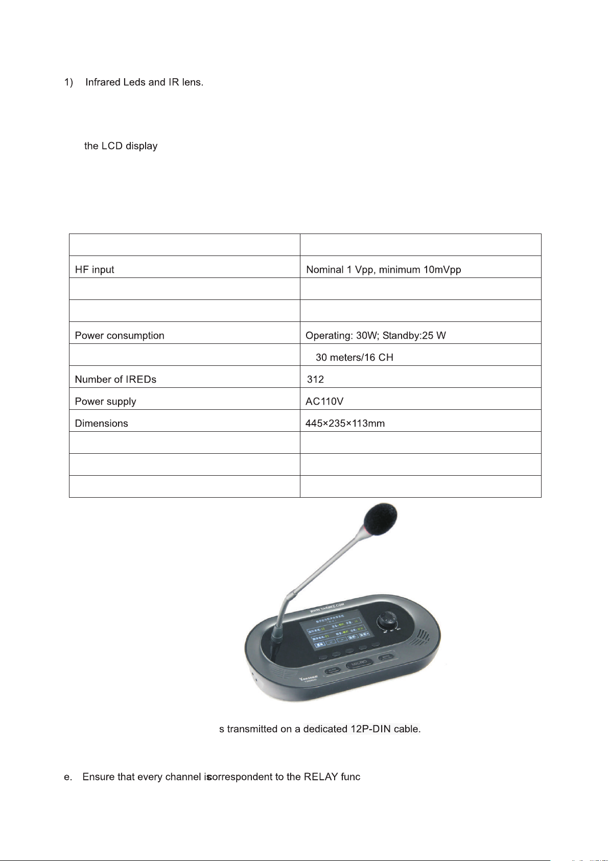
1.3 Digital interpreter console --------------------------------------------------------------------------------------------9
1.3.1 Picture of the actual object ------------------------------------------------------------------------------------------- -9
1.3.2 Features of interpreter console --------------------------------------------------------------------------------------9
1.3.3 Schematic diagram of interpreter console -----------------------------------------------------------------------10
1.3.4 Parameter of interpreter console ----------------------------------------------------------------------------------10
1.4 Digital Infrared receiver ----------------------------------------------------------------------------------------------11
1.4.1 Picture of the actual object ------------------------------------------------------------------------------------------11
1.4.2 Features of digital Infrared receiver -------------------------------------------------------------------------------11
1.4.3 Schematic diagram of digital Infrared receiver -----------------------------------------------------------------11
1.4.4 Parameter of digital Infrared receiver -----------------------------------------------------------------------------12
1.5 Charging unit------------------------------------------------------------------------------------------------------------12
1.5.1 Picture of the actual object ------------------------------------------------------------------------------------------12
1.5.2 Features of charging unit- -------------------------------------------------------------------------------------------12
1.5.3 Schematic diagram of charging unit ------------------------------------------------------------------------------12
1.5.4 Parameter of charging unit ------------------------------------------------------------------------------------------13
1.6 Repeater unit-----------------------------------------------------------------------------------------------------------13
1.6.1 Picture of the actual object ------------------------------------------------------------------------------------------13
1.6.2 Features of repeater unit---------------------------------------------------------------------------------------------13
1.6.3 Parameter of infrared microphone unit ---------------------------------------------------------------------------13
2. System installation---------------------------------------------------------------------------------------------------------- 14
2.1 System connection diagram-----------------------------------------------------------------------------------------14
2.2 Warning---------------------------------------------------- --------------------------------------------------------------15
the receiver unit---------------------------------------------------------------------15
ator----------------------------------------------------------------------------------15
-----------------------------------------------------15
2.3 Planning------------------------------------------------------------------------------------------------------------------16
2.3.1 Aspects of infrared distribution systems--------------------------------------------------------------------------16
2.3.2 Directional sensitivity of the receiver------------------------------------------------------------------------------16
2.3.3 The footprint of the radiator------------------------------------------------------------------------------------------17
2.3.4 Position the radiator---------------------------------------------------------------------------------------------------18
2.3.5 Cabling--------------------------------------------------------------------------------------------------------------------20
2.3.6 Set the delay switches------------------------------------------------------------------------------------------------21
2.3.7 Determine the radiator delay switch positions-----------------------------------------------------------------21

2
----------------------------------------------------------22
2.5 Transmitter installation and connection--------------------------------------------------------------------------22
2.5.1 Transmitter installation------------------------------------------------------------------------------------------------22
method--------------------------------------------------------------------------------22
2.5.3 Connect radiators------------------------------------------------------------------------------------------------------23
2.5.4 Connect interpreter console-----------------------------------------------------------------------------------------23
2.5.5 Connect other external audio sources----------------------------------------------------------------------------24
-------------------------------------------------------------------------------------------24
2.6.1 Installation of radiator with bracket---------------------------------------------------------------------------------24
2.6.2 Caution item-------------------------------------------------------------------------------------------------------------25
2.7 Installation of interpreter console----------------------------------------------------------------------------------25
2.7.1 Mounting and dismounting the microphone---------------------------------------------------------------------25
2.7.2 Connection headset to interpreter console----------------------------------------------------------------------25
2.8 Installation of infrared receiver-------------------------------------------------------------------------------------26
2.8.1 Battery install------------------------------------------------------------------------------------------------------------26
2.8.2 Connect earphone to receiver---------------------------------------------------------------------------------------26
2.9 System setting----------------------------------------------------------------------------------------------------------26
2.9.1 System mode------------------------------------------------------------------------------------------------------------26
2.9.2 Interpreter setting------------------------------------------------------------------------------------------------------28
3. System operation and function-------------------------------------------------------------------------------------30
3.1 Digital infrared transmitter-------------------------------------------------------------------------------------------30
3.3.1 On/Off the transmitter---- --------------------------------------------------------------------------------------------30
--------------------------------------------------------------30
--------------------------------------------------------------30
----------------------------------------------------------------30
3.2 Interpreter Console----------------------------------------------------------------------------------------------------30
3.3.1 On/Off the interpreter---- ---------------------------------------------------------------------------------------------30
3.3.2 Monitor (Input channel) --- -------------------------------------------------------------------------------------------31
3.3.3 Interpreter microphone on/off---------------------------------------------------------------------------------------31
3.3.4 Mute function------------------------------------------------------------------------------------------------------------31
3.3.5 Slow function------------------------------------------------------------------------------------------------------------31
3.3 Digital infrared receiver-----------------------------------------------------------------------------------------------32
3.3.1 On/Off the receiver---- ------------------------------------------------------------------------------------------------32
3.3.2 Channel/volumdee bug--------------------- --------------------------------------------------------------------------32
3.3.3 Battery capacity warning---------------------------------------------------------------------------------------------32
3.3.4 Automatically off--------------------------------------------------------------------------------------------------------32
3.4 Charging unit------------------------------------------------------------------------------------------------------------33
4. Tr oubleshooting-------------------------------------------------------------------------------------------------------34

3
Important Safety Instructions
1. Please read this safety instruction carefully before installing and using the apparatus.
2. Please keep these safety instructions for future reference.
3. Please strictly heed all warnings in the user’s guide.
4. Please follow all the operation instructions in the user’s guide.
5. To prevent from any hazardd, o not use this apparatus near water.
6. Equipment cleaning: Make sure to turn off the power supply and disconnect the units before cleaning.
Clean only with a dry soft cloth.
7. Do not block any ventilation openings. Install in accordance with the manufacture’s instructions.
8. Do not install near any heat sources such as radiators. Heat registers, stoves or other apparatus
9. Grounding: 3-wire grounding plug, and do not defeat the safety purpose of this plug. A grounding type
plug has two blades and a third grounding prong, the third prong are provided for your safety. If the
your outlet, consult an electrician for replacement of the obsolete outlet.
10. Protect the power cord from being walked on or pinched particularly at plugs, convenience
receptacles, and the point where they exit from the apparatus.
only use attachments/accessorie
12. Use only with the cart, stand, tripod, bracket, or table sp
apparatus. When a cart is used, use caution when moving the cart/apparatus combination to avoid
injury from tip-over.
13. Unplug this apparatus during lighting storms or when unused fro long periods of time.
14. Refer all servicing to neares rvicing is required when the apparatus has
been damaged in any way, such as power-supply cord or plug is damaged, liquid has been spilled or
objects have fallen into the apparatus, the apparatus has been exposed to rain or moisture, does not
operate normally, or has been dropped.
15. Do not place the equipment on any uneven or unstable stand; original product package or appropriate
package should be used to avoid damage caused by strong impacts during transportation.
adiators in one system should not exceed prescribed quantity. For
service, please contact the nearest service center.
17. All products are guaranteed for 1 year excluding the following cases:
a. all damage or malfunction caused by human negligence;
b. Damage or malfunction caused by improper operating by operator;
c. Parts damage or loss caused by disassembling the product by non-authorized personnel.
on cable to connect the system equipment.

4
This label appears on the rear of the unit duce to space limitations

5
1. Overview
eless distribution of audio signals via
infrared radiation. It can be used in a simultaneous interpretation system for international conferences
where multiple languages are used. To enable all participants ot understand the discussion, interpreters
simultaneously translate the speaker’s language as required. These interpretations are distributed
throughout the conference venue, and delegates select the langu
through headphones. The system can also be used for music distribution.
This digital language distribution system comprises one or more of the following:
Infrared transmitter
The transmitter is the core of the system. Four types are available:
- Inputs for 4 audio channels
- Inputs for 8 audio channels
- Inputs for 12 audio channels
- Inputs for 16 audio channels
Infrared radiator
The radiators can be .
- The raidator support up to 32 channels audio transmission
Infrared receivers
Five multi-channel infrared receivers are available:
- 4 audio channels
- 8 audio channels
- 12 audio channels
- 16 audio channels
- 32 audio channels
ith disposable batteries. Charging
circuitry is incorporated in the receiver.
Interpreter consoles
Five Interpreter consoles are available:
- 4 audio channels
- 8 audio channels
- 12 audio channels
- 16 audio channels
- 32 audio channels
Charging equipment
- The charging unit is for charging and storing 24 infrared receivers.
Repeater
-The repeater for boost the transmission signals of interpreter consoles
age of their choice and listen to it

6
1.1 Digital Infrared transmitter
1.1.1 Picture of the actual object
1.1.2 Features of digital infrared transmitter
a. Fully digital wireless transmission technology. System confo
es disturbance from all types of lighting systems.
c. The system provides multi-channel 4/8/12/16 for option
d. High security, prevent external interference.
lay system information
g. Installation: 19-inch frame
1.1.3 Schematic diagram of digital Infrared transmitter
1) Power on/off switch: Power switch (Press I to turn on the power, power indicator is lighting, press O to
turn off the power)
e transmitter status,. It also use as an
interactive display for
the communication properly, the
working, the transmitter may has problem.
4) Menu button: To operate the configuration system inputs/languages/safety settings, etc.
Men u N or ma l Aux iliar y Al arm
IR Mo nitor
Digi tal I nfr ared Langu age D ist ribution S yst em
Sta tu s
POW ER
ON
OFF I C CARD
1 2 3 4 5 6 7 8 9 10
Audio Out
Audio In
0 1 2 4 6 8 10 12 143 5 7 9 11 13 15
0 1 2 4 6 8 10 12 143 5 7 9 11 13 15
Interpreter Unit Conference System RS 232 Auxiliary Alarm
AF in HF out
1 2 3 4
AC220V~50Hz~60Hz
Fuse:T2AL 250V
11 12 13 14 15 16 17 18 19
YARMEE
YARMEE

7
5) Normal button: To setting the normal working status—interpre
one.
6) Auxiliary button: To setting the auxiliary working status—mu
one.
7) Alarm button: To setting the alarm working status—emergency
one.
D will lighting when management card correctly insert.
9) Management card interface: Use he correct card during setting
d signal as the radiator output. This can be
used for monitoring purposes.
connection interpreter consoles
12) Conference connector: Use for connect compatible conference system
14) Auxiliary audio inputs: Femal udio inputs to connect auxiliary audio
signals such a emergency audio signal
audio signal, when this function
available, system will distribute the emergency audio signal to all output channels and overriding all
other audio inputs.
he radiators. Up to 30 Radiators can be
loop-through connected to each output.
17) Audio signal output: 4/8/12/16 audio connectors to connect other audio equipments. The number of
connectors depends on the transmitter type
18) Audio signal input: 4/8/12/16 audio connectors to connectx eternal unbalanced audio input signals.
The number of connectors depends on the transmitter type.
19) Power supply: The transmitter has automatic voltage selection. A power cable is provided.
1.1.4 Parameter of infrared transmitter
Items Parameter
Modulation frequency
3 part 7
Audio frequency response 20Hz-10kHz (-3dB) at standard quality
Total harmonic distortion at 1 kHz <0.05%
Crosstalk attenuation at 1 kHz >80dB
Dynamic range >80dB
>80dB(A)
Power consumption Operat
r must insert t

8
Items Parameter
Operating temperature range 0-40 degree
-200V ~ 50Hz-60Hz
Dimensions 485×355×90mm
Mounting 19” rack mounting
N.W 8kg
1.2 Digital Infrared radiator
1.2.1 Picture of the actual object
1.2.2 Features of digital infrared transmitter
b. Radiates & distributes up to 32 channels of digital audio signal
c. Digitized audio ensures very high audio quality
d. Powerful compression technique ransmission.
oor stand or optional tripod
f. Easily daisy-chained together to expand coverage
g. Angle of half intensity: ±22°
1.2.3 Schematic diagram of digital infrared radiator
X10M
On
Off
Delay C ompen satio n
Signa l Out Signa l In
AC 110V/ 220V 50 /60Hz
Fuse: 2A/2 5W
Power
On
Off
2
13 4 5 6 7

9
2) Delay compensation switches: te for differences in cable lengths to
the radiators.
3-4) Channel selector: An up/down switch to select an audio channel. The channel number is shown on
5) Power input: Male power plug connector. The radiators have automatic voltage selection.
6) Radiator power on/off switch
7) Bracket hole: Tapped hole to mount the suspension bracket.
1.2.4 Parameter of digital Infrared radiator
Items Parameter
Angle of half intensity ±22°
Total optical peak intensity 24 W/sr
Transmission distance <
-220V ~ 50Hz-60Hz
Operating temperature range 0-40 degree
Mounting Standard: Bracket, Option: tripod
N.W 4.2kg
1.3 Digital interpreter console
1.3.1 Picture of the actual object
1.3.2 Features of interpreter console
a. Digital audio processing and transmitting technology.
b. Up to 32 Channel audio signal
c. Interpreter consoles powered by the transmitter.
d. Voice adjustable and with prevention on feedback
tion respectively.
f. Delegates speak too fast; give a request for slow the speed.
8-position switches to compensa

10
g. Automatic numbering on system units
h. Prevention on interpreter's cough
1.3.3 Schematic diagram of interpreter console
1) Microphone red indicator to show mic state (on/off)
ctors for connecting the interpreter
console to the transmitter and for loop-through connection to other interpreter consoles.
6) Earphone jack (ø 3.5mm)
7) Menu key
ss this button (microphone of the
interpreter unit must be active) to remind him/her to slow down)
9) Microphone on/off switch (Micro): Press this button to turn on the microphone and the red indicating
light will be activated, press this button again to turn off the microphone.
10) Microphone mute key (Mute): Push and hold the “Mute” button to temporarily disable the microphone.
Release this button on voice recovery.
reter’s function set knob
12) Built-in Hi-Fi loudspeaker
1.3.4 Parameter of digital Infrared radiator
Items Parameter
Frequency response 50Hz – 20kHz
Sensitivity -42 ± 2dB
Length of gooseneck 410mm
Dimensions 300×150×70mm
Operating temperature range 0-40 degree
N.W 1.7kg
1 2
6 7 8 9 10 11 12 13
4 53

11
1.4 Digital infrared receiver
1.4.1 Picture of the actual object
1.4.2 Features of digital infrared receiver
a. Fully digital wireless transmission technology. Receiver con
b. Pocket size wireless handheld unit
c. Accommodates up to 32 different languages
d. Channel selector and headphone connector
e. Power on/off switch and volume level control
echargeable batteries
g. No power used when headphone is disconnected
h. Aluminum carrying case
tion
1.4.3 Schematic diagram of digital infrared receiver
l. An antenna symbol is visible when the
receiver picks up an infrared signal of adequate quality. A battery symbol is visible when the batteries
are almost empty.
2-3) Channel selector: An up/down switch to select an audio channel. The channel number is shown on
4) On/Off button: When headphone is connected, the receiver switches to stand-by state. Pressing the
On/Off button switches the receiver from stand-by to on. To switch back to stand-by, press and hold
the button approx. 2 seconds. When the headphone is removed, the receiver switches automatically
to the off-state.
5) Charging contacts: Used in combination with the charging equipment to recharge the batteries
6) Headphone connector: A 3.5mm (0.14 inch) stereo jack output socket for the headphone.
8) Volume control: A slider to adjust the volume +/-
s provided for receivers
1
2
3
4
5
6
7
8

12
1.4.4 Parameter of digital Infrared receiver
Items Parameter
Angle of half sensitivity ± 50°
Headphone output level at 2.4V 450 mVrms (Speech at maximum volume, 32 ohm
headphone)
Headphone output frequency range 20 Hz to 10 kHz
Headphone output impedance 32 ohm
Max. signal-to-noise ratio 78 dB(A)
Supply voltage 1.8 to 3.6 V, nominal 2.4 V
Power consumption at 2.4V (battery voltage) 60 mA (speech at maximum volume, 32 ohm
headphone)
Power consumption (standby) 60 mA
Dimensions 157×49×25mm
Operating temperature range 0-40 degree
N.W 150g without battery
1.5 Charging unit
1.5.1 Picture of the actual object
1.5.2 Features of charging unit
a. The charging unit can recharge up to 24 pieces receivers
at once.
b. The charging unit contains the power supply with
automatic input voltage selection.
are integrated in each receiver.
d. The charging circuitry checks if a batteries is present and
controls the charging process receivers per charging
1.5.3 Schematic diagram of digital infrared receiver
POW ER AC 22 0V
FUS E 10A
1 2 3 4

13
1) Receiver positions: One charging unit can charge up to 24 receivers simultaneously.
2) Power input: Male power input socket. The charging unit has automatic input voltage selection. A
power cable is provided.
3) Power on/off switch
4) Power cable and batteries storage position
1.5.4 Parameter of charging unit
Items Parameter
-220V ~ 50Hz-60Hz
Consumption Rating 66W
Maximum charging current of each unit 220mA
Charge quantity 24
Charging time About 2 to 2.5 hours
Charging status
Operating temperature range 0-40 degree
Dimension 630x370x290mm
N.W 10.5kg
1.6 Repeater unit
1.6.1 Picture of the actual object
1.6.2 Features of repeater unit
The standard interpreter cable length from transmitter to the first interpreter console is 10 meters, if the
cable length more than 10 meters, the system should use repeater unit to boost the signals, each repeater
unit can support 10 meters length.
1.6.3 Parameter of repeater unit
Items Parameter
Consumption Rating 1.5W
Support cable length 10 meters
Operating temperature range 0-40 degree
Dimension 120x40x50mm

14
2. System installation
2.1 System connection diagram
Audio Out
Audio In
0 1 2 4 6 8 10 12 143 5 7 9 11 13 15
0 1 2 4 6 8 10 12 143 5 7 9 11 13 15
Interpreter Unit Conference System RS 232 Auxiliary Alarm
AF in HF out
1 2 3 4
AC220V~50Hz~60Hz
Fuse:T2AL 250V
1 5 Pi e c e s
22º
22º
22º
22º
22º
22º
22º
22º
Auxiliary
audio inputs
Emergency
audio inputs

15
2.2 Warning
l If the units demonstrate any problems, such as abnormal sound, smoke, heat from or damage to
power cables, disconnect the power plug from the outlet and contact your sales representative.
Battery charger)
l Uncoil the power cables before use, Do not bundle the cables d
l Do not pull on the cable. Hold the plug section and insert/remove it in a straight line, damaged cables
may result in electric shock, m attery charger)
l Do not place anything on the power cables. Do not route them under a rug or furniture. (Transmitter,
l
Do not cover the units with cl ith poor ventilation.
Doing so traps heat, and may resu
l If you do not use the units for long periods of time, disconnect the power plugs from the outlet.
l Do not disassemble the units. Touching the inside of the units may result in electric shock
l Do not expose the units to any strong shock
l Do not expose the units to direct sunlight, heat from heating appliances, high temperatures, or dust
l Do not expose the units to high humidity or moisture
Water that accidentally enters the inside of the units may resu
l Do not touch the power cables or
l
a protective grounding connection
l
unit by the power switch. In case of emergency, turn off this switch or unplug the power cable from
ng of the receiver unit
l Do not drop the unit
l If you do not use the unit for a long
l The dedicated battery should be used
l Do not cover the infrared section
lbe certain that they are securely fastened
lsuch as direct sunlight, incandescent
plays
l Noise may be generated by interference regardless of the opera
away from infrared-emitting objects
l Do not place any obstructions around the radiator
ery charger handling
l If the charging terminal is dirty, poor contact will prevent the battery from being charged properly.
Periodically clean the charging terminals
l The battery charger may become hot during charging. Use it in a well-ventilated area
l After the battery is fully charged, turn off the battery charger or remove the receivers
oth or place them in locations w
plugs with wet hand.(Transmit
e battery
periods of time, remove th

16
2.3 Planning
The system is based on transmission by modulated infrared radiation. Infrared radiation forms part of the
electromagnetic spectrum, which is composed of visible light, radio waves and other types of radiation. It
has a wavelength just above that of visible light. Like visible
passes through translucent materials such as glass. The infrared radiation spectrum in relation to other
relevant spectra is s
2.3.1 Aspects of infrared distribution systems
A good infrared distribution system ensures that all delegateins a conference venue receive the
distributed signals without disturbance. This is achieved by us ing enough radiators, placed at well planned
positions, so that the conference venue is covered with uniform ate strength. There
f the infrared signal, which must be
considered when planning an infrared radiation distribution system. These are discussed in the next
sections.
2.3.2 Directional sensitivity of the receiver
The sensitivity of a receiver is at its best when it is aimed directly towards a radiator. The axis of maximum
sensitivity is tilted upwards at an angle of 45 degrees (see th
decrease the sensitivity. For rotations of less than +/- 45 degrees this effect is not large, but for larger
rotations the sensitivity will decrease rapidly.
Directional characteristics of the receivers
45
45
90

17
2.3.3 The footprint of the radiator
The cross section of the 3-deimensional radiation pattern with
signal is strong enough to ensure proper reception, when the receiver is directed towards the radiator. As
shown, the size and position of the footprint depends on the mounting height and angle of the radiator.
Radiator mounted at 15° to the ceiling
Radiator mounted at 45° to the ceiling
Radiator mounted perpendicular (at 90°) to the ceiling

18
2.3.4 Position the radiator
Since infrared radiation can reach a receiver directly and/or v
this into account when considering the positioning of the radiators. Though it is best if receivers pick up
direct path infrared radiation, r
minimized. Radiators should be positioned high enough not to be blocked by people in the hall (see the
Infrared signal blocked by a person in front of the participant
Infrared signal not blocked by a person in front of the participant
the participant is situated clear from obstacles and walls, so a combination of direct and diffused radiation
from a number of surfaces to the
participant.

19
For concentrically arranged conference rooms, centrally place da, ngled radiators located high up can
ting surfaces, such as a darkened
path infrared radiation from radiators
positioned in front. When the direction of the receiver changes, e.g. with varying seat arrangements,
mount the radiators in the corn gure)
Radiator position for covering seats in a square arrangement
If the audience is always directed towards the radiators, you d o not need radiators at the back (see the
Radiator positioning in a conference hall with auditorium seating and podium
If the path of the infrared signals is partially blocked, e.g. under balconies, you should cover the ‘shaded’
area with an additional rad
Radiator for covering seats beneath a balcony
Table of contents