3
MODEL 100227 RIDING SULKY
INTRODUCTION
This manual covers the setup and proper SAFE
operationofMODEL 100227RIDING SULKY.
When riding the SULKY, always follow the safety
and operating instructions below as well as those
covered in the Commercial Mower Operator's
Manual:
SAFETY/OPERATING INSTRUCTIONS
1. DO NOT modify sulky nor use it on non-
approved machines.
2. Makesurethatthesulkyisproperly attached
to the machine and is in good working order
prior to use.
3. Only one rider (the machine operator) per
sulky.
4. DO NOT allow use by untrained operators.
5. Use appropriate personal protective
apparatus, such as boots, gloves, etc.
6. Practice operation of machine without
attachment until familiar with the controls.
7. Practice operation of machine with sulky
attached on large open, level terrain with no
obstacles present before use. The sulky will
affect the machine operation, especially on
slopes, when turning and when stopping.
8. DONOTridesulkyovercurbs,rocks,rootsor
other obstructions.
9. Slowdownbeforemakingturnsanduseextra
caution on rough terrain and on slopes.
10. Travelacrossslopesisrecommended,avoid
operation on steep slopes.
11. Avoid making sharp turns/jack knifing.
12. Keep feet on foot rest at all times.
13. NEVER tow loads behind sulky.
14. Look behind and down before backing up to
be sure of a clear path. Use extra care when
operatinginreverse.NOTE:Beforeoperating
inreverse,theoperatorMUSTdismount(type
II,IIIandV)sulkies.
15. Use extra care when loading and unloading
the machine with sulky attached.
TECHNICAL ASSISTANCE
If you have any questions pertaining to your
machine contact your dealer.
For technical assistance please write: Yazoo/
Kees, P.O. Box 8, Beatrice, NE, 68310 or call:
402-223-2391, Customer Service Department.
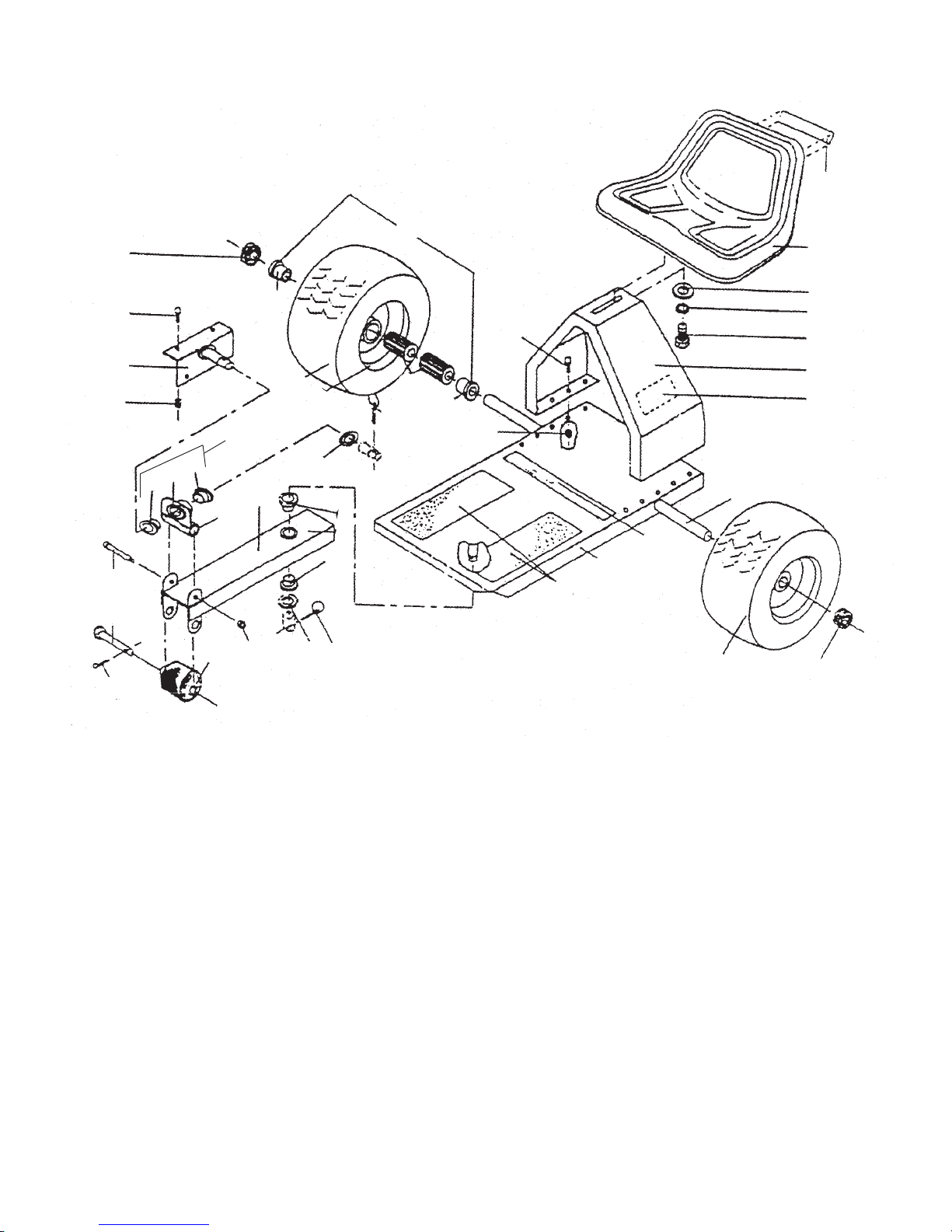
ASSEMBLY
Before starting assembly, refer to illustration for
proper location of parts and fasteners.
STEP1:Removeallpartsfromcartonandinspect
for shipping damage. Remove tire assemblies
(17) and clamp collars (20) from axle (7)
STEP2:Insertaxle(7)withtabup,throughholein
deck (13) flange, from inside, slide through far
enough for other end of axle to clear opposite
flange, swing up and slide into opposite hole until
tabcontactsflange.Axlemayalsobeinsertedinto
frontholeinthedeckflangewhentheseatandseat
mount are in the forward position.
STEP 3: Remove lynch pin (26) and one bushing
(15) from pivot pin on underside of deck (13).
Place tongue assembly (12) and bushing (15) on
pivotpin,securebyinsertinglynchpin(26)through
cross hole of pivot pin and lock in place.
STEP 4: Place seat (18) on mounting weldment
(9) and secure with flat washer (28), lock washer
(29) and bolt (32). Adjust to desired position and
tighten securely.
STEP5:Attachhitchweldment(11)torearflange
of mower case with bolt (27) and nut (33). NOTE:
Bolts are to be inserted from outside and nuts
attached from underside of mower case.
STEP 6: Check and tighten all fasteners. Check
tire pressure (28 psi MAX). Apply lubrication to
wheelbearingthroughgreasefittinginwheeluntil
visible between clamp collar and wheel bearing
flange.
FRONTADJUSTMENTHOLE