INSTRUCTION 9000 – MODU-CAB 6 1/31/07
PUMP WITH SINGLE RAIL QUICK LIFT
1) Location
In most cases the pit size, pump elevation, piping arrangement, access door location, and other features have
been established and are shown on an installation drawing (refer to construction installation drawing). The pump
or pumps should be located in the pit on opposite side from the influent opening.
2) Checking Rotation
It will be necessary to check the rotation of the motor and pump impeller before installing the unit into the basin.
CAUTION: BE CAREFUL NOT TO HAVE HANDS, FEET, CLOTHING OR OTHER OBJECTS IN OR NEAR
THE PUMP SUCTION OPENING WHEN THE POWER IS ON!
The motor leads should be marked, or the starter diagram location inside the starter should be marked, or both,
so that the connections can be broken and remade with accuracy. It is important that the pump rotates in the
direction for which it was designed. Lay the pump on its side and connect the motor lead to the permanent
source of power. Quickly turn the power on and off to get the impeller spinning. Examine the impeller through
the suction opening. It should be turning counterclockwise. If not, change any two of the motor leads and
recheck. As soon as the motor is rotating in a counterclockwise direction, mark the leads and diagram as
mentioned above. The above instructions apply to three phase motors. Single-phase motors cannot be reversed
in this manner, and rotation is factory checked. If rotation reversal is required for single-phase motors, consult
the factory.
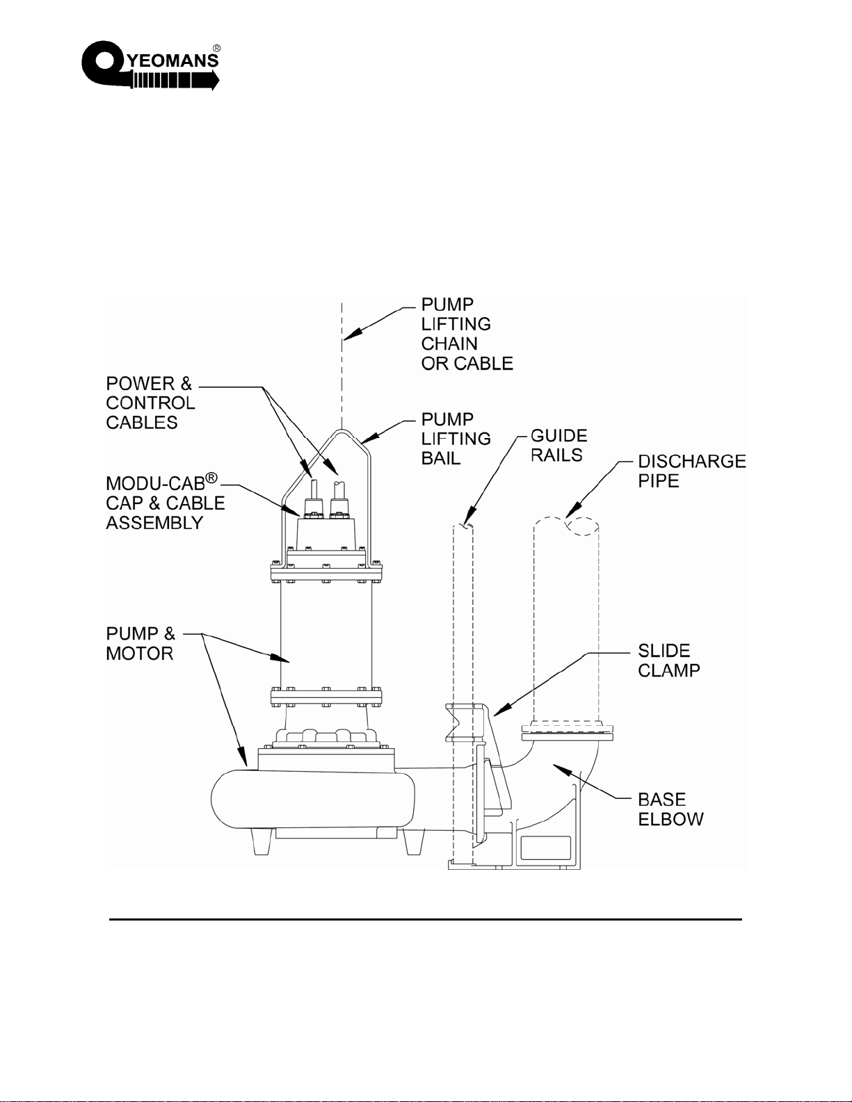
3) Foundation and Guide Rail
With the quick lift arrangement the pump is supported by the base elbow, which also supports the discharge
piping. The pit floor should be designed to cant' the load of the entire assembly of pump, base elbow, guide
rails, and discharge piping. The foundation bolts for the base elbow are located off the clear opening in the pit
cover as shown in the installation drawing referenced in Paragraph 1) above and should be long enough to
accommodate 1" of grout under the foot of the base elbow. The base elbow should be shimmed from the rough
concrete floor until the horizontal pipe flange is level in both directions. Then grout the base, and allow the grout
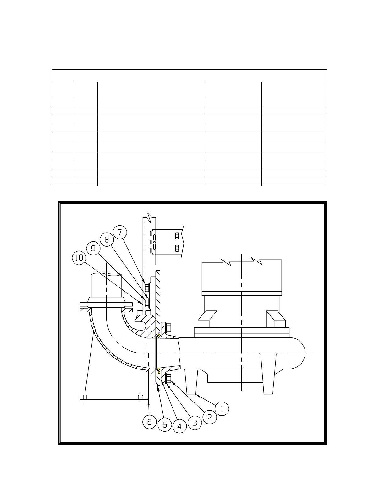
to harden before tightening the foundation bolt nuts. Referring to Figure 1 (Drawing 103785) the lower end of the
guide rail is inserted into the base elbow. The upper end of the guide rail is then attached to the pit opening;
cover angle, or whatever method has been provided. (This attachment varies with installations and is the
responsibility of the customer.) The rail has lateral support by means of pipe straps connected to the discharge
pipe. Again referring to Figure 1, slide plate (part 5) is shipped with two shoes (part 9) attached. Insert the
neoprene jam washer (part 4) as shown, then bolt the assembly to the pump discharge flange.
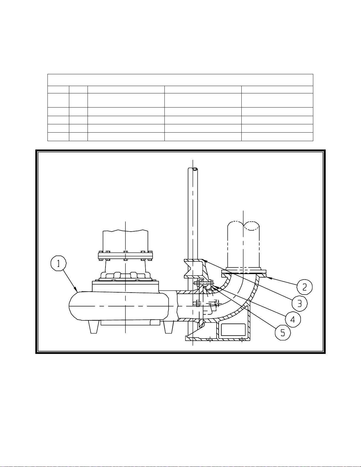
4) Piping
In most cases, the discharge piping arrangement has been established and a typical arrangement is shown on
the installation drawing; however, there are several rules to follow. The pipe size should be no smaller than that
of the base elbow. Gate and check valves should be provided in each discharge pipe with the check valve
placed between the gate valve and the pump. The valves may be either inside or outside the pit. The weight of
the piping is supported on the base elbow but long (10' or more) vertical sections may require lateral support
from the pit wall.