Page3
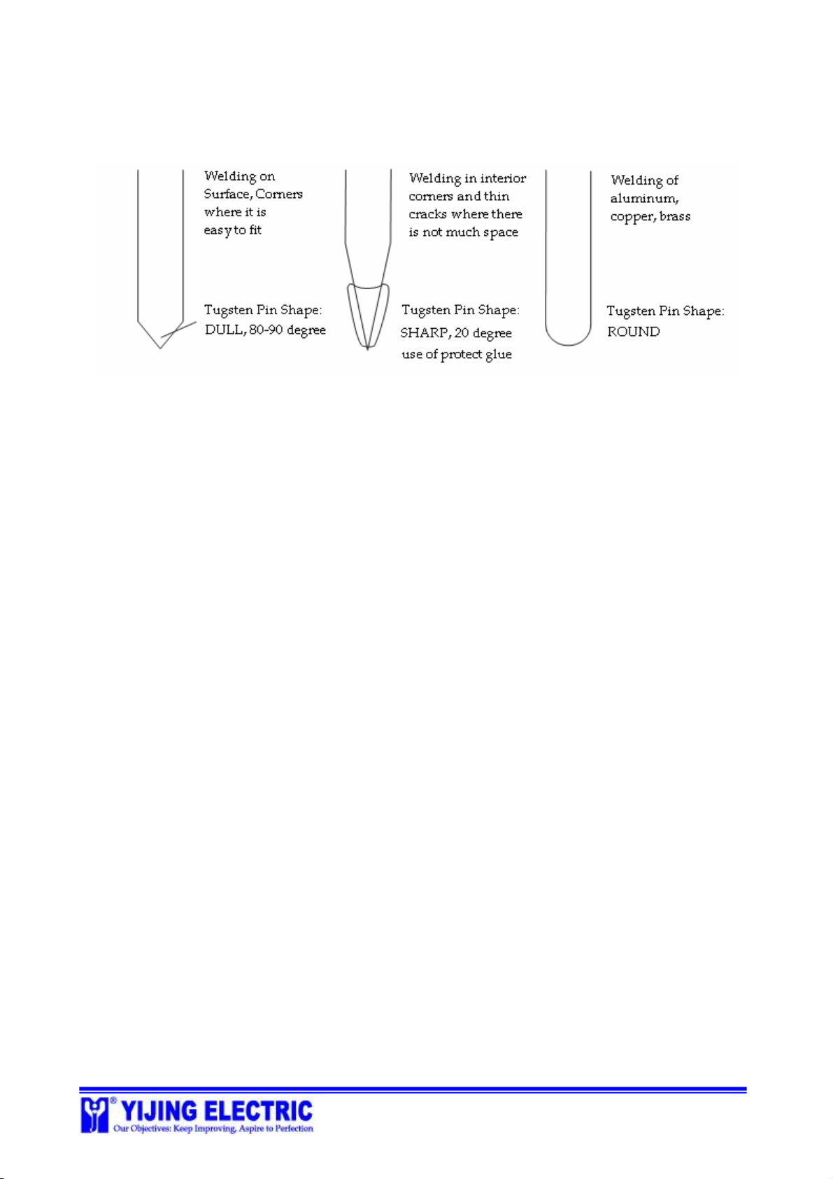
TungstenTip
Intheweldingtorch,thereisamountedtip, whichismadeoftungsten.Thedesignofthetip
varies as theweldingtask changes. Plssee thefollowing pictures.
*NOTE:
1.Dull pinisthemoststableshapeoftungstenpin.We suggesttheuseofthisshapeasmuchas
possible.
2.Ifthedull pincannotfit,trythesharppin.
3. Theprotectglueisaspecial-madeheat-resistanceglue.Itcanprotectthetungstenpinand
prolong itsservicelife.
4. Theroundpinbestpreventpin-stuck.Itishighly recommendedfor welding ofaluminum,
copperandbrass.
5. Normally,weusepinsof 1.6mm.Ifrepairinglargeoutput,changethepinto 2.0mm, to
prolong itsservicelife.
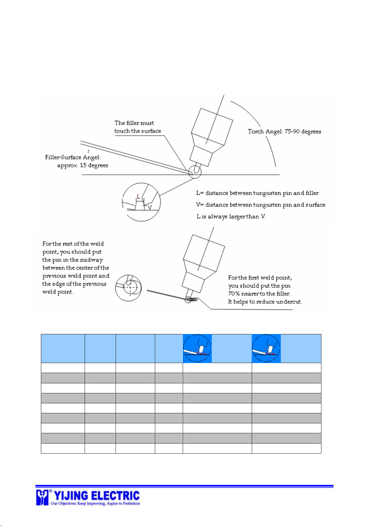
Filler
We generallyrecommendthatyouusefillerofthesametypeastheworkpiecethatisweldedon.
For iron,werecommendfillerwithlowWc%.
Set FillerMode
Thisfunctionisaveryusefulaid,whenyouneedweldonverydelicate,complicatedpositions.
Youcanpre-weldthefillerwithsetfillermode,andthenyouusetheTIGmodetore-weldthe
fillerthoroughly ontotheposition.
Thisfunctioncanfree yourhandfromthetraditionaltiresomewayoffeedingthefillers. Youcan
stabletheTIGwelding torchby bothyourhands andgetmuchbetterweldingquality.
This functioncanalsobeusedtopreventpotentialdamagetosurroundingareas.
To useSet-FillerMode,youmustmakesure:
1)Thegroundcableis firmlyfastenedonthefrontpanel;
2)Thegroundplateis ingood contactwiththeworkpiece;
3)Theareatobeweldediscleanandfree ofstain,grease, etc..
Duringsettingfillers, youneedtopressdownhardonthefiller.Forfillerdia.of0.3mm,we
suggestpulsecurrencyvalue30.Forfillerdia. of1.0mm,wesuggestpulsecurrencyvalue99.