YILMAZ REDÜKTÖR E Series User manual

E Series
Worm Gearboxes
OPERATING
INSTRUCTIONS
OIECE0302-0422

Contents ...................................................................................................................02
1- How To Use This Manual......................................................................................... 04
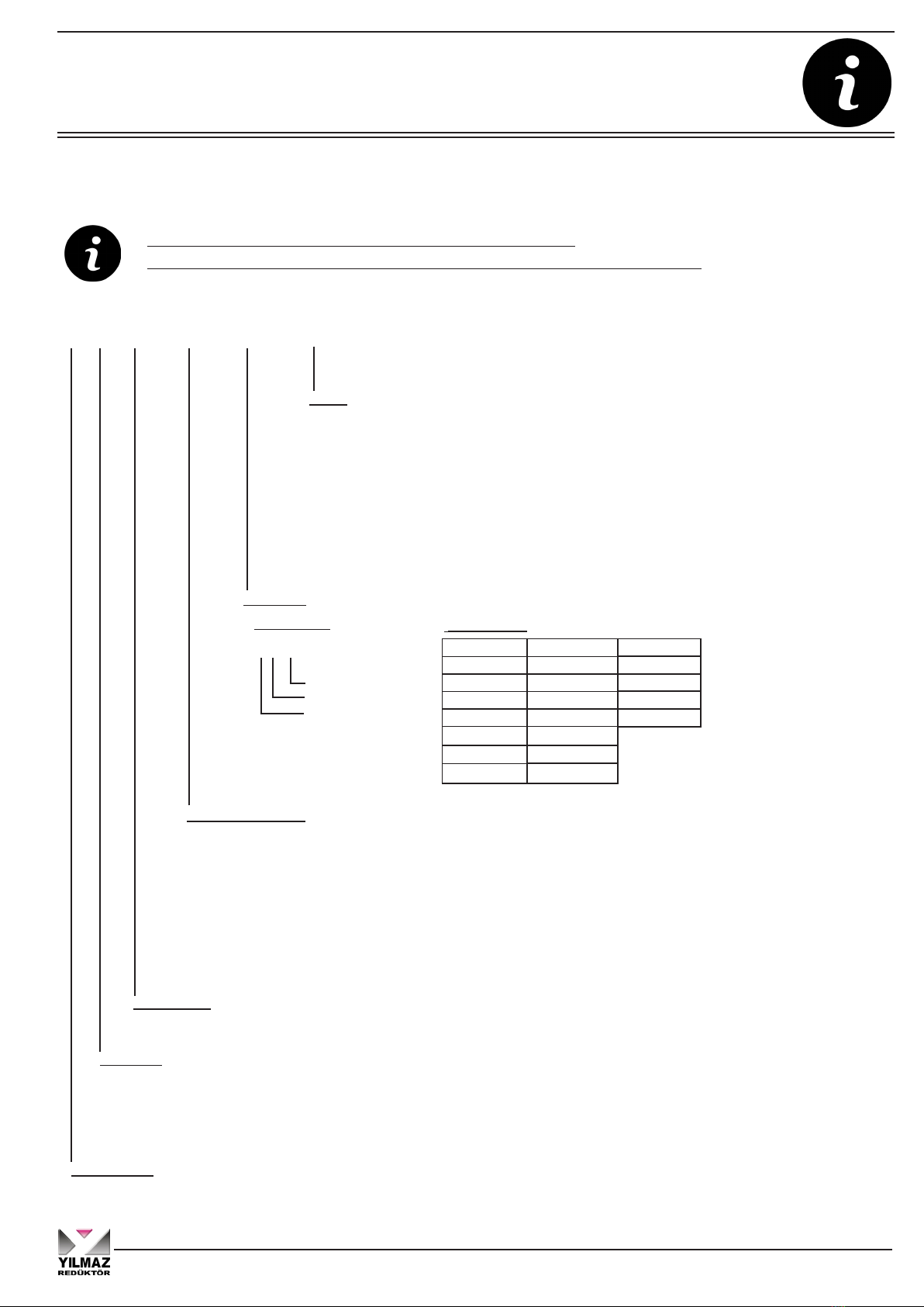
2- Type Designation ..................................................................................................... 05
2.1 Detailed unit designation............................................................................... 05
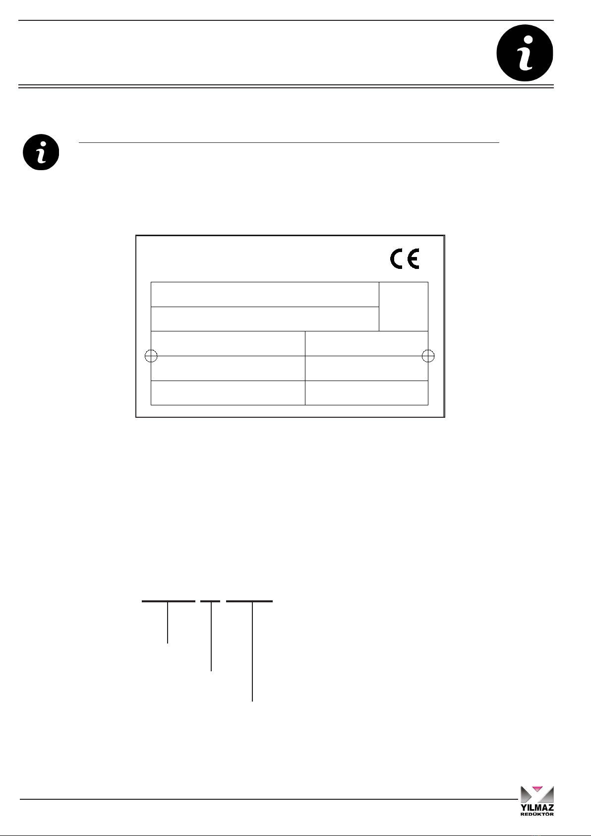
2.2 Nameplate unit designation........................................................................... 06
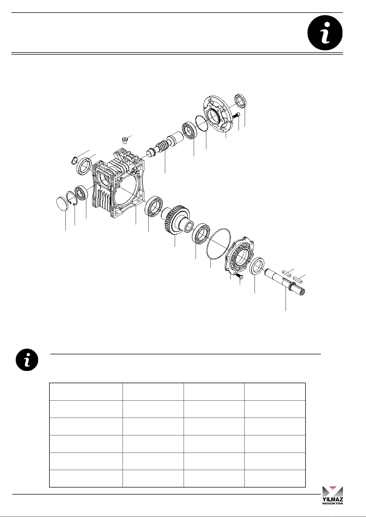
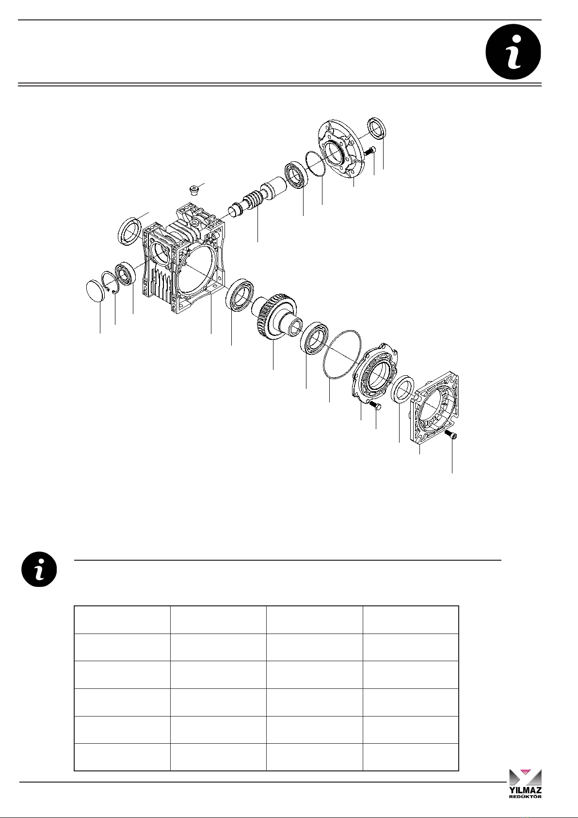
3- Part List of Standard Type Gear Units ................................................................... 07
3.01 E....00 Types ............................................................................................... 07
3.02 E....01 Types ............................................................................................... 08
3.03 E....02 Types ............................................................................................... 09
3.04 E....03 Types ............................................................................................... 10
3.05 E....04 Types ............................................................................................... 11
3.06 E....05 Types ............................................................................................... 12
3.07 E....08 Types ............................................................................................... 13
3.08 ET...00 Types .............................................................................................. 14
3.09 ET...01 Types .............................................................................................. 15
3.10 ET...02 Types .............................................................................................. 16
3.11 ET...03 Types............................................................................................... 17
3.12 ET...04 Types .............................................................................................. 18
3.13 ET...05 Types .............................................................................................. 19
3.14 ET...08 Types .............................................................................................. 20
4- Safety.......................................................................................................................21
4.1 Intented to use .............................................................................................. 21
4.2 Improper Use ................................................................................................ 21
4.3 Safety Instructions......................................................................................... 22
4.3.1 General Safety Instructions.................................................................. 22
4.3.1.1 Working on gear reducer............................................................ 22
4.3.1.2 Operation ................................................................................... 22
4.3.1.3 Maintenance............................................................................... 22
4.3.1.4 Lubricant .................................................................................... 22
4.3.1.5 Ambient Conditions.................................................................... 22
4.4 Tightining Torques......................................................................................... 23
4.5 Case of Fire .................................................................................................. 23
4.5.1 Suitable extinguishing agents, protective equipment............................ 23
4.5.2 Unsuitable extinguishing agents ........................................................... 23
5- Thinks to Check Before the Gear Unit or Geared Motor is Installed ................. 24
5.1 Transportation............................................................................................... 24
5.2 Storage ......................................................................................................... 25
6- Installing The Gear Unit .......................................................................................... 25
6.1 Before you start............................................................................................. 25
6.2 Check the shaft dimensions to fit.................................................................. 26
6.3 Check the ambient temperature.................................................................... 26
6.4 Check the voltage supply.............................................................................. 26
6.5 Check the mounting position......................................................................... 29
6.6 Use the breather plug.................................................................................... 29
6.7 Check the oil level......................................................................................... 29
6.8 Check shaft ends and mounting faces.......................................................... 29
Contents
2
Operating Instructions
E Series

6.9 Cover abrasive ambient............................................................................... 29
6.10 Check accessibility to filling, breather and drain plugs................................. 30
7- Mechanical Installation ........................................................................................... 30
7.1 Installing customer shaft with shoulder.......................................................... 31
7.2 Shaft tightening torques ................................................................................. 32
7.3 Recommended shaft dimensions and disassembling nut dimensions........... 33
7.4 Assembling gear unit with torque arm............................................................ 34
7.5 Fitting output shaft elements......................................................................... 37
7.6 Correct position of output shaft elements ...................................................... 37
7.7 Fitting couplings ............................................................................................. 38
8- Maintenance & Inspection ...................................................................................... 39
9- Lubrication ...............................................................................................................40
9.1 Oil types ......................................................................................................... 40
9.2 Changing the oil ............................................................................................. 41
9.3 Mounting Positions......................................................................................... 41
9.4 Oil Quantities.................................................................................................. 42
10- Troubleshooting Guide ......................................................................................... 43
11- Disposal ................................................................................................................. 46
11.1 Disposal of oil................................................................................................ 46
11.2 Disposal of sealing ........................................................................................ 46
11.3 Disposal of metal........................................................................................... 46
12- Appendix ................................................................................................................47
12.1 Warranty conditions ...................................................................................... 48
12.2 Warranty........................................................................................................ 49
Contents
3
Operating Instructions
E Series

1- How To Use This Manual
Take attention to the following safety and warning signs for proper understanding and quick reference.
Electric Hazard; Can cause severe or fatal injuries.
Mechanical Hazard; Can cause severe or fatal injuries.
Likely to be Hazardous; Can cause minor or fatal injuries.
Damage Risk; Can damage gearbox or environment.
Important Information.
EC Machinery Directive:
Within terms of the EC machinery directive 2006/42/EC, the gearboxes are considered
as not autonomous machine, but as a component to install in machines.
Operation is prohibited within the area of validity of the EC directive, until it has been
determined that the machine, in which this product is installed, corresponds to the regula-
tions within this directive.
The machine manufacturer or user is responsible for taking the necessary pre-
cautions on the machine or at the place where the gearbox will be used, in order
to prevent injury and life-threatening risks by taking into account the shaft, gear
failures etc. that may occur in the gearboxes.
The operating instructions contain important information to ensure;
- Trouble-free operation
- Fulfilment of any rights to claim under guarantee
The operating instruction must be kept close to the gearbox and must be available in
case it is needed.
This operating instruction is written for E series gear units and is applicable only for E
series. If any different type of gearbox is used please ask YILMAZ REDUKTOR for the
operating instructions of that type.
This instruction can be used only for standard type geared units of YILMAZ REDUKTOR.
For special application and modified gear units ask YILMAZ REDUKTOR for validity.
This manual does not cover 94/9/EC compatible gearboxes. For 94/9/EC contact YILMAZ
REDUKTOR.
General Informations
4
Operating Instructions
E Series

Type Designations
Detailed E series gear units designation for ordering
(This Designation is different from the short nameplate designation)
2- Unit Designation
2.1- Detailed unit designation
-For EN Types
Brake
L-220V With Fan
P-24V With Fan
S-220 Without Fan
Z-24 V Without Fan
01-10 Nm
02-25 Nm
04-40 Nm
05-50 Nm
Gearbox Type
E serie
Input Type
N:IEC B5 / B14 Flange without Motor
V:IEC B5 / B14 Flange with Motor
T:Without Motor
Housing Size
E.030, E.040, E.050, E063, E.075, E.080, E.100, E.125.
Output Shaft Option
00 :Hollow Shaft Output
01 :Solid Output Shaft
02 :Solid Output Shaft and with Flange
03 :Flanged and Hollow Shaft Output
04 :With Double Shaft Output
05 :Double Flanged and Double Output Shaft
*06 :With Shaft Extension on the Motor Fan Cover Side
**07 :With Double Input Shaft
08 : Double Flanged and Hollow Output Shaft
E V 063 . 01 - 90S/4 - L05
10-100Nm
20-200 Nm
30-300 Nm
40-400 Nm
Motor Size
For EV types
90S / 4
Pole Number
Frame Lenght
Motor size
A06 :63 B5 A10 :100 B5 A20: 200 B5
B06 :63 B14 B10 :100 B14 A22: 225 B5
A07 :71 B5 A11 :112 B5 A25: 250 B5
B07 :71 B14 B11 :112 B14 A28: 280 B5
A08 :80 B5 A13 :132 B5 A31: 315 B5
B08 :80 B14 B13 :132 B14
A09 :90 B5 A16 :160 B5
B09 :90 B14 A18 :180 B5
*06 code is optional input shaft types for EN and EV types. Can be
shown as EN050.00-07
**07 Code is optional input shaft types for ET Types. Can be shown as
ET050.00-07
5
Operating Instructions
E Series

2.2- Nameplate and unit designation
Nameplate unit designation is a short abbreviation from the detailed designation
A sample name plate for E Series
Abreviations:
Serial N. : Serial Number
M.Pos. : Mounting Position
Type Designation;
Type
EV080.00-90S/4
Output Shaft
Motor Type
Type Designations
M. Pos.:
:Oil
Ratio:
:Type
rpm.:Speed
Power : kW
www.yr.com.tr
MADE IN TURKEY
Serial N.:
YILMAZ REDÜKTÖR
Oil Qty : lt.
EV080.00-90S/4
100536041
1.1 62
23 M1
ISO VG320
(Synthetic Oil) 0.5
6
Operating Instructions
E Series

Part Designation
3- Part List of Standard Type Gear Units
3.1- E....00 Types
1- Oil Seal 7- Bearing 13- Oil Plug 19- Seal
2- Bolt 8- Housing 14- Worm Gear
3- Side Cover 9- Closing Cap 15- Bearing
4- O-ring 10- Circlips 16- O-Ring
5- Bearing 11- Bearing 17- Input Flange
6- Worm Wheel 12- Seal 18- Bolt
Standard E...00... type basic part diagram. Parts may differ for special applications.
Standard Part List
1
2
3
4
5
6
7
8
11
10
9
12
13
14
15
16
17
1819
7
Operating Instructions
E Series

3.2- E....01 Types
1- Key 7- Bearing 13- Bearing 19- O-ring
2- Solid Output Shaft 8- Worm Wheel 14- Circlips 20- Input Flange
3- Seal 9- Bearing 15- Seal 21- Bolt
4- Bolt 10- Housing 16- Oil Plug 22- Seal
5- Side Cover 11- Closing Cap 17- Worm Gear
6- O-ring 12- Circlips 18- Bearing
Standard E...01... type basic part diagram. Parts may differ for special applications.
Standard Part List
3
4
5
6
7
8
9
10
13
12
11
15
16
17
18
19
20
21 22
14
1
2
1
Part Designation
8
Operating Instructions
E Series

Part Designation
3.3- E....02 Types
1- Key 7- Side Cover 13- Closing Cap 19- Worm Gear
2- Solid Output Shaft 8- O-Ring 14- Circlips 20- Bearing
3- Bolt 9- Bearing 15- Bearing 21- O-Ring
4- Flange 10- Worm Wheel 16- Circlips 22- Motor Flange
5- Seal 11- Bearing 17- Seal 23- Bolt
6- Bolt 12- Housing 18- Oil Plug 24- Seal
4
3
2
11
10
5
6
7
8
9
12
15
14
13
17
18
19
20
21
22
23 24
16
1
1
Standard E...02... type basic part diagram. Parts may differ for special applications.
Standard Part List
9
Operating Instructions
E Series

3.4- E....03 Types
1- Bolt 7- Bearing 13- Bearing 19- Motor Flange
2- Flange 8- Worm Wheel 14- Seal 20- Bolt
3- Seal 9- Bearing 15- Oil Plug 21- Seal
4- Bolt 10- Housing 16- Worm Gear
5- Side Cover 11- Closing Cap 17- Bearing
6- O-Ring 12- Circlips 18- O-Ring
2
1
9
8
3
4
5
6
7
10
13
12
11
14
15
16
17
18
19
20 21
Standard E...03... type basic part diagram. Parts may differ for special applications.
Standard Part List
Part Designation
10
Operating Instructions
E Series

Part Designation
3.5- E...04 Types
1- Key 7- Bearing 13- Bearing 19- Bearing
2- Solid Output
Shaft 8- Worm Wheel 14- Circlips 20- O-Ring
3- Seal 9- Bearing 15- Washer 21- Input Flange
4- Bolt 10- Housing 16- Seal 22- Bolt
5- Side Cover 11- Closing Cap 17- Oil Plug 23- Seal
6- O-Ring 12- Circlips 18- Worm Gear
20
21
22 23
2
1
1
1
15
14
3
4
5
6
7
8
9
10
13
12
11
16
17
18
19
Standard E...04... type basic part diagram. Parts may differ for special applications.
Standard Part List
11
Operating Instructions
E Series

3.6- E....05 Types
6
7
8
9
13
16
15
14
18
19
20
21
22
23
24 25
5
4
12
11
2
10
45
17
1
1
1
3
1- Key 7- Bolt 13- Housing 19- Oil Plug 25- Seal
2- Solid Output Shaft 8- Side Cover 14- Closing Cap 20- Worm Gear
3- Circlips 9- O-Ring 15- Circlips 21- Bearing
4- Bolt 10- Bearing 16- Bearing 22- O-Ring
5- Flange 11- Worm Wheel 17- Circlips 23- Input Flange
6- O-Ring 12- Bearing 18- Seal 24- Bolt
Standard E...05... type basic part diagram. Parts may differ for special applications.
Standard Part List
Part Designation
12
Operating Instructions
E Series

Part Designation
3.7- E....08 Types
3
4
5
6
7
10
13
12
11
14
15
16
17
18
19
20 21
2
1
9
8
12
1- Bolt 7- Bearing 13- Bearing 19- Input Flange
2- Output Flange 8- Worm Wheel 14- Seal 20- Bolt
3- Seal 9- Bearing 15- Oil Plug 21- Seal
4- Bolt 10- Housing 16- Worm Gear
5- Side Cover 11- Closing Cap 17- Bearing
6- O-Ring 12- Circlips 18- O-Ring
Standard E...08... type basic part diagram. Parts may differ for special applications.
Standard Part List
13
Operating Instructions
E Series

3.8- ET...00 Types
14
16 17
18
20
15
19
1
2
3
4
5
6
7
8
11
10
9
12
13
1- Seal 5- Bearing 11- Bearing 17- O-Ring
2- Bolt 6- Worm Wheel 12- Seal 18- Flange
3- Side Cover 7- Bearing 13- Oil Plug 19- Bolt
4- O-ring 8- Housing 14- Worm Gear 20- Seal
5- Bearing 9- Closing Cap 15- Key
6- Worm Wheel 10- Circlips 16- Bearing
Standard ET...00... type basic part diagram. Parts may differ for special applications.
Standard Part List
Part Designation
14
Operating Instructions
E Series

Part Designation
3.9- ET...01 Types
1- Key 7- Bearing 13- Bearing 19- Bearing
2- Solid Output Shaft 8- Worm Wheel 14- Circlips 20- O-Ring
3- Seal 9- Bearing 15- Seal 21- Giriş Flange
4- Bolt 10- Housing 16- Oil Plug 22- Bolt
5- Side Cover 11- Closing Cap 17- Worm Gear 23- Seal
6- O-Ring 12- Circlips 18- Key
Standard ET..01... type basic part diagram. Parts may differ for special applications.
Standard Part List
17
19 20
21
23
18
22
3
4
5
6
7
8
9
10
13
12
11
15
16
14
1
2
1
15
Operating Instructions
E Series

3.10- ET...02 Types
Standard ET..02... type basic part diagram. Parts may differ for special applications.
Standard Part List
1- Key 7- Side Cover 13- Closing Cap 19- Worm Gear 25- Seal
2- Solid Output Shaft 8- O-Ring 14- Circlips 20- Key
3- Bolt 9- Bearing 15- Bearing 21- Bearing
4- Flange 10- Worm Wheel 16- Circlips 22- O-Ring
5- Seal 11- Bearing 17- Seal 23- Input Flange
6- Bolt 12- Housing 18- Oil Plug 24- Bolt
5
6
7
8
9
12
15
14
13
17
18
16
4
3
2
11
10
1
1
19
21 22
23
25
20
24
Part Designation
16
Operating Instructions
E Series

Part Designation
3.11- ET....03 Types
1- Bolt 7- Bearing 13- Bearing 19- O-Ring
2- Flange 8- Worm Wheel 14- Seal 20- Motor Flange
3- Seal 9- Bearing 15- Oil Plug 21- Bolt
4- Bolt 10- Housing 16- Worm Gear 22- Seal
5- Side Cover 11- Closing Cap 17- Key
6- O-Ring 12- Circlips 18- Bearing
Standard ET...03... type basic part diagram. Parts may differ for special applications.
Standard Part List
3
4
5
6
7
10
13
12
11
14
15
2
1
9
8
16
18 19
20
22
17
21
17
Operating Instructions
E Series

3.12- ET...04 Types
Standard ET...04... type basic part diagram. Parts may differ for special applications.
Standard Part List
1- Key 7- Bearing 13- Bearing 19- Key
2- Solid Output Shaft 8- Worm Wheel 14- Circlips 20- Bearing
3- Seal 9- Bearing 15- Washer 21- O-Ring
4- Bolt 10- Housing 16- Seal 22- Input Flange
5- Side Cover 11- Closing Cap 17- Oil Plug 23- Bolt
6- O-Ring 12- Circlips 18- Worm Gear 24- Seal
3
4
5
6
7
8
9
10
13
12
11
16
17
2
1
1
1
15
14
18
20 21
22
24
19
23
Part Designation
18
Operating Instructions
E Series

Part Designation
3.13- ET...05 Types
Standard ET...05... type basic part diagram. Parts may differ for special applications.
Standard Part List
1- Key 7- Bolt 13- Housing 19- Oil Plug 25- Bolt
2- Solid Output Shaft 8- Side Cover 14- Closing Cap 20- Worm Gear 26- Seal
3- Circlips 9- O-Ring 15- Circlips 21- Key
4- Bolt 10- Bearing 16- Bearing 22- Bearing
5- Output Flange 11- Worm Wheel 17- Circlips 23- O-Ring
6- Seal 12- Bearing 18- Seal 24- Input Flange
6
7
8
9
13
16
15
14
18
19
5
4
45
17
1
1
1
3
12
11
2
10
20
22 23
24
26
21
25
19
Operating Instructions
E Series

3.14- ET....08 Types
Standard ET...08... type basic part diagram. Parts may differ for special applications.
Standard Part List
1- Bolt 7- Bearing 13- Bearing 19- O-Ring
2- Output Flange 8- Worm Wheel 14- Seal 20- Input Flange
3- Seal 9- Bearing 15- Oil Plug 21- Bolt
4- Bolt 10- Housing 16- Worm Gear 22- Seal
5- Side Cover 11- Closing Cap 17- Key
6- O-Ring 12- Circlips 18- Bearing
3
4
5
6
7
10
13
12
11
14
15
2
1
9
8
12
16
18 19
20
22
17
21
Part Designation
20
Operating Instructions
E Series
This manual suits for next models
1
Table of contents
Popular Water Pump manuals by other brands

vacuubrand
vacuubrand MV 10 VARIO select Instructions for use

Grundfos
Grundfos Unilift KP 150 manual

Edelbrock
Edelbrock For Small Blaock Chevrolet V6&V8&V9 8882 General instructions

Wilo
Wilo Atmos GIGA-NHT Installation and operating instructions

SFA
SFA SANIACCESS 1 installation instructions

SFA
SFA SANICONDENS Clim Classic quick start guide

Wilo
Wilo American-Marsh Pumps 482 EGB Series Installation and operating manual

GORMAN-RUPP PUMPS
GORMAN-RUPP PUMPS 2D-X.75 1P Installation, operation and maintenance manual

Truper
Truper PRETUL MOTB-2P manual

Zipper Mowers
Zipper Mowers ZI-DOP600 Operation manual

Clarke
Clarke PW80A Operation & maintenance instructions

ATURIA
ATURIA TK instruction manual