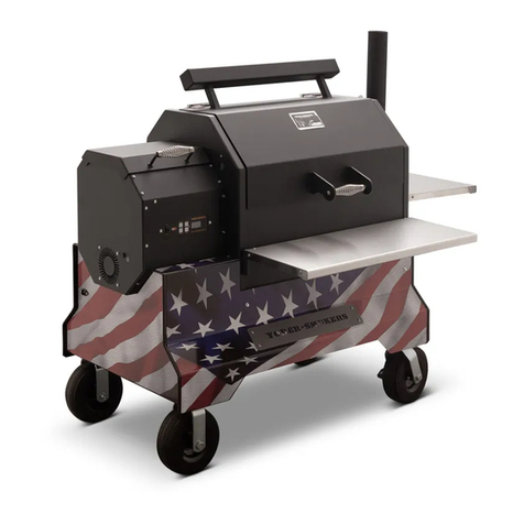
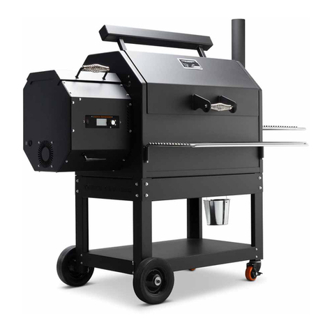
Yoder Smokers S Series User manual

RETROFIT CONVERSION
YS1500 INSTALLATION INSTRUCTIONS
CAUTION: BEFORE BEGINNING THIS PROCEDURE, ENSURE THAT THE POWER CORD TO
THE SMOKER IS DISCONNECTED! FAILING TO DO SO MAY RESULT IN BODILY INJURY.
COMPETITION CART MODELS REQUIRE UNPLUGGING THE POWER CORD FROM THE
HOPPER LOCATED UNDER THE CART.


TABLE OF CONTENTS
Getting Started............................................................................................................................................................1
Installation Instructions............................................................................................................................................2
ACS Controller Setup...............................................................................................................................................15
Quick Start Guide.....................................................................................................................................................17
Yfi App Connection..................................................................................................................................................21

1
5/16” Socket | Small Adjustable Wrench | 7/16” Wrench | Small Pliers
Small Phillips Head Screwdriver | Small Flat Head Screwdriver | Drill
PARTS INCLUDED
( 1 ) ACS™ Controller
( 1 ) Wi-Fi Antenna
( 1 ) Wi-Fi Antenna Extension
( 2 ) ACS Probes
( 1 ) Factory Probe Kit
( 1 ) Short Thermocouple
( 1 ) Insulation Panel
( 4 ) Self-Drilling Screws (spare)
( 1 ) 1/4” Drill Bit
BEFORE YOU GET STARTED
Begin by confirming all the parts included in this kit are accounted for. The diagram below
shows each item in this kit. Should any items be missing, please contact Customer Service
tools you’ll need
THINGS TO REMEMBER
UNPLUG
POWER CORD
remove
cookING grates
REMOVE
HEAT DIFFUSER
EMPTY
THE HOPPER

2
step 1
Remove the end panel by removing
the eleven self-drilling screws using the
5/16” socket to gain access into
the hopper.
step 2
Disconnect the two wires (one green,
one white) from the outer fan, then
disconnect the two purple wires from
the fuse holder.
step 3
Disconnect the two wires (one green,
one white) from the inner fan.
WHITE
WIRE
GREEN
WIRE
WHITE
WIRE
GREEN
WIRE
ROTATED VIEW
OF OPPOSITE
CORNER

3
step 4
Using a 5/16” socket, remove the two
controller screws that secure the control
box to the hopper.
step 5
Pull out the control box and open to gain
access to the wiring on the back side
of the green circuit board.
step 6
Disconnect the two thermocouple wires,
white & red, from the circuit board using
a small flat head screwdriver. Pull the
wires out of the control box and set the
control box to the side.
WHITE WIRE
(Terminal TC1A)
RED WIRE
(Terminal TC1B)
THERMOCOUPLE
SHIELDED LINE
TERMINAL BLOCK

4
step 9
From inside the cooking chamber, remove
the seven hex head self-drilling screws
using a 5/16” socket. Save these screws for
mounting the hopper assembly. DO NOT
REMOVE the two screws from the hopper
hanging bracket. From inside the cooking
chamber, pull the steel braided thermocouple
wire out of the hopper and let it hang loose
inside the cooking chamber to hook-up with
the new controller.
step 8
Unplug all wiring at spade connector
ends and remove the controller
assembly with harness. Leave the
green ground wire hanging inside
the chamber.
step 7
Disconnect igniter connector located
inside the hopper.
TO CONTROL BOX
TO IGNITER INSIDE
COOKING CHAMBER

5
step 10
Underneath the front side of the chamber,
remove the self-drilling screw under the cart
next to the fire box using a 5/16” socket.
NOTE: Save this screw for remounting
the hopper assembly.
step 11
Underneath the back side of the chamber,
remove the two self-drilling screws under
the cart next to the fire box using a 5/16”
socket.
NOTE: Save these screws for remounting
the hopper assembly.
step 12
Remove the hopper from the cooking
chamber by lifting up from the hopper
mounting bracket and pulling away from
the cooking chamber. Ensure the igniter
fully clears the opening in the end panel
before setting the hopper to the side.
NOTE: Some previous production units
have the igniter installed on the wall of
the cook chamber; if so, pull the wiring
into the cook chamber until the hopper
is replaced.

6
step 13
Using the ¼” drill bit provided, drill
a hole into the hopper (as shown ) that
measures 2.5 inches from the center
of the existing hole.
NOTE: Do not use the existing hole;
the antenna requires more clearance
provided by drilling the new hole
as shown.
Ă
2.50”
DO NOT USE EXISTING HOLE
DRILL NEW HOLE HERE
.25”
3.00”
step 14
Locate the Wi-Fi antenna extension
wire. Remove the hex nut and lock
washer from the extension wire. Insert
the threaded male end through the new
hole (drilled in Step 12) on the front of
the hopper as shown. Next, place the
lock washer onto the threaded male
end, followed by the nut. Then secure it
into place using the 7/16” wrench
and 5/16” socket. NEW HOLE
DO NOT USE
THIS HOLE
step 15
Attach the Wi-Fi antenna and tighten
it by hand.

7
step 17
Hang the hopper on the cooking chamber
mounting bracket. Make sure to line up the
holes of the hopper to the holes on
the chamber.
NOTE: Make sure the antenna is clear of
the cart before fulling installing the hopper.
step 18
Secure the hopper to the cooking chamber
wall using the seven hex head self-drilling
screws saved from Step 9. Do not tighten
the screws until all have been installed.
NOTE: Take care to not overtighten the
screws as the holes can be stripped out.
step 16
Install the insulation into the end of
the hopper as shown. Ensure the
insulation is fully tucked in behind the
mounting flanges.
NOTE: Failure to install the
insulation will void the warranty on
the ACS controller.

8
step 19
Reinstall the self-drilling screw
removed on Step 10 underneath the
front side of the cart and start to
secure the fire pot.
step 20
Reinstall the two remaining self-
drilling screws removed on Step 10
underneath the back side of the cart
and finish securing the fire pot.
step 21
To replace the thermocouple, begin by
removing the thermocouple and bracket
from the chamber using a phillips head
screwdriver and 5/16” socket. Discard
the thermocouple assembly, but save the
screws and nuts for use in the next step.
NOTE: The short thermocouple must be
installed for proper operation with the
new ACS controller.

9
step 24
Carefully remove the box from the
controller by sliding the harness through
the slot in the box.
step 23
Locate the ACS control box assembly
with harness and remove the four screws
located on the back side of the box.
step 22
Using the screws and nuts from Step 21,
install the short thermocouple into the
same the holes in the chamber from
the previous thermocouple.

10
step 26
Slide the harness and thermocouple wire
through the slot on the box and secure the
box to the controller using the four screws
removed earlier. NOTE: Take care to not
crimp or pinch the ribbon cable or any
wires in the process of closing the box.
step 27
Remove the two phillips head screws
from the faceplate.
step 25
Inside the chamber, feed the steel braided
thermocouple wire back through the
wall of the cooking chamber and into
the hopper. Remove as much slack as
possible from the thermocouple to the hole
in the cooking chamber. Using the small
flat head screwdriver, install the red and
white thermocouple wires into the correct
terminals on the ACS controller. When
installing the new thermocouple wires,
please double check your connection to
make sure there is little to no exposed wire
where they are connected to the terminal.
WHITE WIRE RED WIRE

11
step 30
Reconnect red and black wiring spade
terminals to auger drive motor.
AUGER
MOTOR
BLACK
WIRE
RED
WIRE
step 29
Attach the Wi-Fi extension wire
to the controller using a small
adjustable wrench.
step 28
Install the ACS controller into the hopper
and secure it in place using the two screws
removed from the faceplate.

12
step 32
Connect the two short green and white
wires to the inner fan.
GREEN WIRE
WHITE WIRE
step 33
Connect the igniter to the control board.
NOTE: If your grill has the igniter mounted
on the wall of the cook chamber, first
remove the burn grate and then feed
the igniter wires into the hopper.
TO CONTROL BOX
TO IGNITER INSIDE
COOKING CHAMBER
step 31
Reconnect the spade connectors to
the A/C power socket.
A/C POWER
WHITE
WIRE
GREEN
WIRE
BLACK
WIRE

13
step 36
Ensure all wires are free of both fans and
the auger drive motor. Lastly, attach the
end panel to the hopper using the eleven
self-drilling screws.
step 35
Connect the two purple wires to
the fuse holder.
step 34
Connect the two wires (one green, one
white) to the outer fan.
WHITE
WIRE
GREEN
WIRE

14
THIS COMPLETES
THE HARDWARE INSTALL
step 37
If your unit does not include a factory probe
port like the one in the image, follow the
instructions included in the factory probe
port kit. NOTE: Running the probe wires
under the lid will cause damage to the
wire and shorten the life of the probe.

15
step 1
Plug in your grill and press the power button.
You will see the system setup screen on the
display.
step 3
Once again confirm you have the YS1500
model selected, then press the selector
button next to the save option. If you have
selected the incorrect option, press the
selector button next to the back option and
return to STEP 2. NOTE: This is a one-time
selection that can only be reversed by the
Yoder Smokers Customer Service team.
Selecting the incorrect model will cause
the unit to operate erratically.
step 2
Push and release the rotary selector knob
until the YS1500 appears. Confirm you have
the correct model selected, then press the
selector button next to the save option.
step 4
Once you have saved the model,
the controller will reset.
back
save
System Setup
Model: NONE
Degrees: Fahrenheit
Yoder Ver: 1.0.12
FB Ver: 0.2.44
back
save
Save Setup?
Model: YS1500
Degrees: Fahrenheit
Yoder Ver: 1.0.12
FB Ver: 0.2.44
back
save
System Setup
Model: YS1500
Degrees: Fahrenheit
Yoder Ver: 1.0.12
FB Ver: 0.2.44
Settings Saved
Restarting in 3 Seconds
ACS CONTROLLER SETUP

16
BLANK PAGE

17
POWER
BUTTON
SELECTION
BUTTONS
LCD DISPLAY
SCREEN
ROTARY
SELECTOR
INDICATOR
LIGHT
TEMPERATURE
PROBE JACKS
POWER BUTTON – Powers the grill on and o. Once the grill is turned on, and a fire has started, pressing the power button
to turn the unit o will initiate shut down mode. This mode allows the fans to continue running to ensure a safe, full burn of
any pellets left in the firepot. The unit will turn o once the grill reaches 125°F or runs for 18 minutes, whichever occurs first.
SELECTION BUTTONS – These buttons are used to make selections throughout the menu.
LCD DISPLAY SCREEN – Displays all content.
ROTARY SELECTOR – Allows you to navigate the menu by rotating the knob and also allows you to make selections or
switch between options by pressing in on the knob.
INDICATOR LIGHT – Lit when power to the unit is on, and when the grill is in shut down mode.
TEMPERATURE PROBE JACKS – Plug in your temperature probes to be able to view food
temperature on the display screen.
QUICK START GUIDE
Other manuals for S Series
2
This manual suits for next models
3
Table of contents
Languages:
Other Yoder Smokers Grill manuals

Yoder Smokers
Yoder Smokers YS 1500 User manual

Yoder Smokers
Yoder Smokers YS 480 User manual
Yoder Smokers
Yoder Smokers YS 640 User manual

Yoder Smokers
Yoder Smokers YS 480 User manual

Yoder Smokers
Yoder Smokers YS 480 User manual

Yoder Smokers
Yoder Smokers Backyard Smoker User manual
Yoder Smokers
Yoder Smokers YS 640 User manual