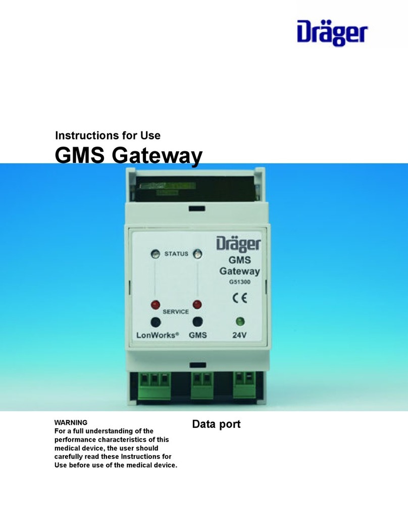
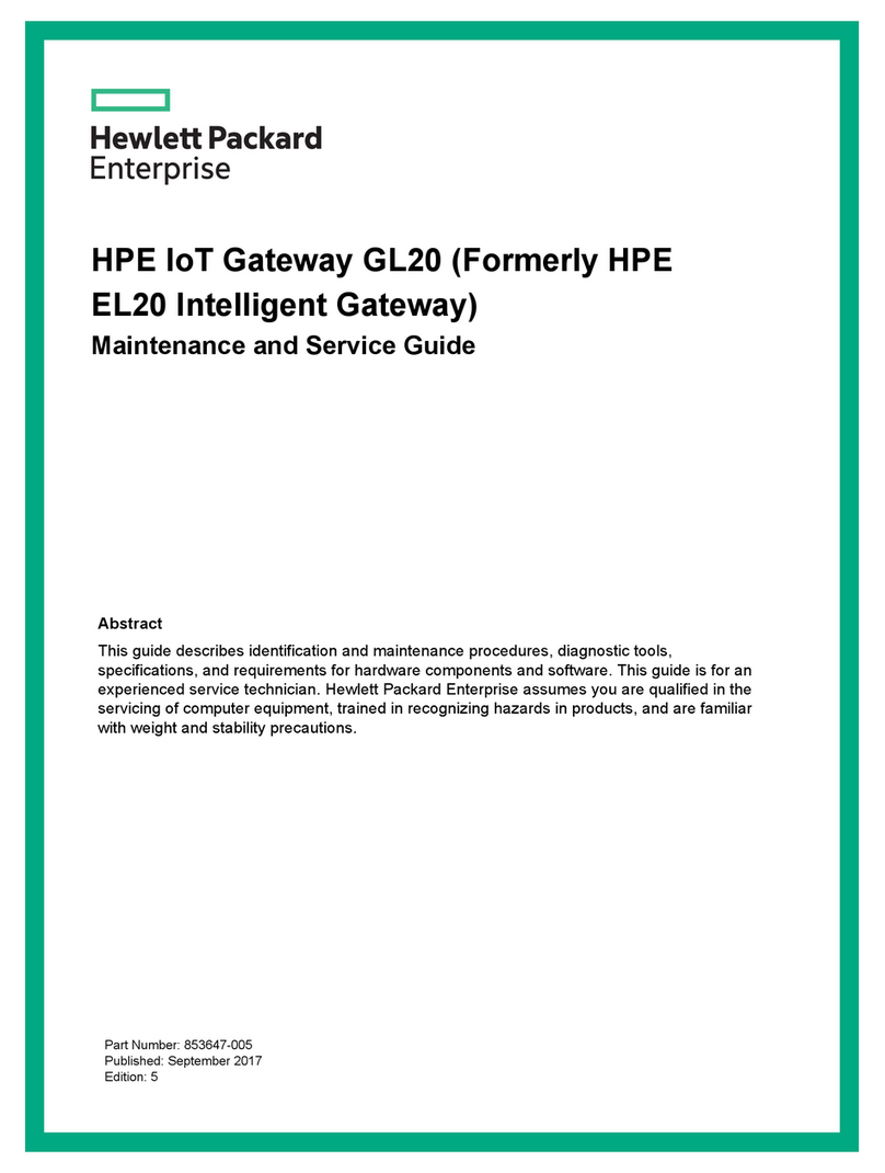
YOKOGAWA YFGW710 User manual

User’s
Manual YFGW710
Field Wireless Integrated Gateway
Read Me First
IM 01W01F01-11EN
IM 01W01F01-11EN
7th Edition
This document species the important information to use this product correctly and
safely and the Use Consent Contract of Attached Software for Field Wireless Integrated
Gateway.
Before use the product, be sure to read this document rst.
Contents
Introduction ...................................................................................................2
Safety Precautions .......................................................................................4
Explosion Protected Type Specications .............................................. 10
How to Use Online Manual ....................................................................... 23
Preparation to Install YFGW710 Attached Software .............................. 23
Copyright and Trademark Notices .......................................................... 24
About User’s Manual ................................................................................. 25
Information of User’s Manual Revision .................................................. 25
YFGW710 Software License Agreement ................................................. 26

2
<Read Me First>
IM 01W01F01-11EN
Introduction
This manual (IM 01W01F01-11EN) describes the safety precautions, explosion protected
type specications and the license agreement of attached software for the YFGW710.
There are three documents including this one for the YFGW710 listed below. Read them
along with this manual.
Documents No. Document name Description
IM 01W01F01-01EN YFGW710 Field Wireless
Integrated Gateway
This manual is stored in the attached DVD-ROM
for YFGW710. It describes installation, wiring,
operation,maintenance and specication of the
YFGW710.
IM 01W01F01-11EN YFGW710 Field Wireless
Integrated Gateway
Read Me First
This manual. It describes the safety precaution,
explosion-protected type specications and the
license agreement of the attached software for the
YFGW710.
GS 01W01F01-01EN YFGW710 Field Wireless
Integrated Gateway
Product specication including detailed model and
sufx code, optional specications and accessory of
YFGW710.
n Regarding This User's Manual
l This manual should be provided to the end user. Please recommend end users
to keep this manual at hand and refer to it as needed.
l Before use, read this manual thoroughly to comprehend its contents.
l The purpose of the user’s manual is to describe details of functions provided
in this product, not to warrant the product's suitability to the specic purposes
of customers.
l No part of this manual may be reproduced in any form without Yokogawa's
written permission.
l The contents of this manual may be changed without prior notice.
l All reasonable effort has been made to ensure the accuracy of the contents of
this manual. However, if any errors or omissions are found, please inform any
of sales ofces listed on the back cover or your local distributor.
l Special specications are not described.
l Please note that this user's manual may not be revised for any specication
changes, construction changes or operating part changes that are not consid-
ered to affect function or performance.

3
<Read Me First>
IM 01W01F01-11EN
n ATEX Documentation
l This is only applicable to the countries in European Union.
GB
DK
I
E
NL
SF
P
F
D
S
LT
LV
PL
EST
SLO
H
BG
RO
M
CZ
SK
GR

4
<Read Me First>
IM 01W01F01-11EN
Safety Precautions
n Safety, Protection, and Modication of the Product
l Safety, Protection, and Modication of the Product
l In order to protect the operator, product, and system controlled by the prod-
uct, observe the safety precautions described in this user’s manual. If users
handle contrary to these instructions, we can not guarantee the safety.
l If this instrument is used in a manner not specied in this user’s manual, the
protection provided by this instrument may be impaired.
l Modication of the product is strictly prohibited.
l If customers attempt to repair or modify explosion protected type products
and fail to return them to their original state, the explosion protected structure
of this product will be lost, resulting in a hazardous state. All repairs and modi-
cations of the product must be consulted with Yokogawa.
l If any protection or safety circuit is required for the system controlled by the
product or for the product itself, prepares it separately.
l Be sure to use the spare parts approved by Yokogawa Electric Corporation
(hereafter simply referred to as YOKOGAWA) when replacing parts or consum-
ables.
l The following symbols are used in the product and user’s manual to indicate
that there are precautions for safety:
CAUTION
Indicates that caution is required for operation. This symbol is placed on the parts necessary to
refer to the user’s manual for protecting the operator and equipment. In the user’s manuals you
will nd precautions to avoid physical injury or death of the operator, including electrical shocks,
injuries of human body, and so on.
WARNING
Indicates instructions that must be observed in order to prevent the software or hardware from
being damaged or the system from becoming faulty.

5
<Read Me First>
IM 01W01F01-11EN
IMPORTANT
Indicates important information required to understand operations or functions.
NOTE
Draws attention to information essential for understanding the operation and features.
TIP Indicates additional information.
SEE
ALSO
Indicates a source to refer to
Indicates a protective grounding terminal. Before using the product, ground the terminal.
Indicates a functional grounding terminal. Before using the product, ground the terminal.
Indicates a DC supply
n Safe Use of This Product
Please pay special attention to the following points:
(a) Installation
• This instrument may only be installed by an engineer or technician who has an expert
knowledge of this device. Operators are not allowed to carry out installation unless they
meet this condition.
• All installation shall comply with local installation requirements and the local electrical code.
(b) Wiring
• The instrument must be installed by an engineer or technician who has an expert knowl-
edge of this instrument. Operators are not permitted to carry out wiring unless they meet
this condition. All installation shall comply with local installation requirements and the local
electrical code.
(c) Operation
• Take care not to generate mechanical sparking when access to the instrument and periph-
eral devices in hazardous area.
(d) Maintenance
• Please carry out only the maintenance procedures described in this manual. If you require
further assistance, please contact the nearest Yokogawa ofce.
(e) Explosion-Protected Instrument
• Users of explosion-protected instruments should refer rst to “Explosion Proof Specication”
section of this manual.
• The use of this instrument is restricted to those who have received appropriate training in
the device.

6
<Read Me First>
IM 01W01F01-11EN
• Take care not to create sparks when accessing the instrument or peripheral devices in a
hazardous location.
• Repair or modication to this instrument by customer will cause malfunction of explosion
protect function and hazardous situation. If you need to repair or modication, please con-
tact the nearest Yokogawa ofce.
(f) Modication
• Yokogawa will not be liable for malfunctions or damage resulting from any modication
made to this instrument by the customer.
(g) Product Disposal
• The instrument should be disposed of in accordance with local and national legislation/regu-
lations.
(h) Authorized Representative in EEA
• The Authorized Representative for this product in the EEA is:
Yokogawa Europe B.V.
Euroweg 2, 3825 HD Amersfoort, The Netherlands
n Warranty
l The warranty terms of this instrument are described in the quotation. We will
make any repairs that may become necessary during the guaranteed term free
of charge.
l Please contact our sales ofce or your local distributor if this instrument re-
quires repair.
l If the instrument is faulty, contact us with complete details about the prob-
lem and the length of time it has been faulty, and state the model and serial
number. We would appreciate the inclusion of drawings or additional informa-
tion.
l The results of our examination will determine whether the product will be re-
paired free of charge or on an at-cost basis.
n The guarantee will not apply in the following cases:
l Damage due to negligence or insufcient maintenance on the part of the cus-
tomer.
l Problems or damage resulting from handling, operation or storage that vio-
lates the intended use and specications.
l Problems that result from using or performing maintenance on the instrument
in a location that does not comply with the installation location specied by
Yokogawa.
l Problems or damage resulting from repairs or modications not performed by
Yokogawa or someone authorized by Yokogawa.

7
<Read Me First>
IM 01W01F01-11EN
l Problems or damage resulting from inappropriate installation after delivery.
l Problems or damage resulting from disasters such as res, earthquakes,
storms, oods, or lightning strikes and external causes.
n Warranty and Disclaimer
l Yokogawa assumes no responsibilities for this product except as stated in the
warranty.
l Yokogawa shall have neither liability nor responsibility to any person or entity
with respect to any direct or indirect loss or damage arising from using the
product or any defect of the product that Yokogawa can not predict in ad-
vance.
n Notes on Hardware
l Appearance and Accessories
Check the following when you receive the product:
• Appearance
• Standard accessories
Contact our sales representative or your local distributor if the product’s coating has come off or
nay accessories are missing.
l Model and Sufx Codes
The name plate on the product contains the model and sufx codes. Compare them with those in
the general specication to make sure the product is the correct one. If you have any questions,
contact our sales ofce or your local distributor.
n Notes on Attached Software
l Before opening the media package, read YFGW710 Software License Agree-
ment. Once the package is opened, it is thought that the contract is agreed.
l Yokogawa assumes no responsibilities for this software except as stated in
the warranty.
l This software is used with this product exclusively. This can be installed in the
computer which connects with this product.
n Insulation Resistance and Dielectric Strength Test
l Insulation Resistance and dielectric strength test could not be carried out
for YFGW710, due to the circuit ground is connected directly to the frame of
YFGW710 via RF cable shield.

8
<Read Me First>
IM 01W01F01-11EN
n Regulatory Compliance for Radio and Telecommunication
Please conrm that an installation region fullls a standards, require additional regulatory information and
approvals, contact to Yokogawa Electric Corporation.
l Radio and Telecommunications Terminal Equipment Directive (R&TTE)
We, Yokogawa Electric Corporation hereby declare that this equipment, model YFGW510 is in
compliance with the essential requirements and other relevant provisions of Directive 1999/5/EC.
The CE declaration of conformity for R&TTE for this product can be found at http://www.
yokogawa.com/d/
● EMC Conformity Standards
EN 301 489-1, EN 301 489-17, EN 61326-1 Class A, Table 2 (For use in industrial locations),
EN 55011 Class A, Group 1, EN 61000-6-2
CAUTION
This instrument is a Class A product, and it is designed for use in the industrial environment.
Please use this instrument in the industrial environment only.
● Safety Conformity Standards
Applicable standard: EN 61010-1, EN 62311
(1) Pollution Degree 2
“Pollution degree” describes the degree to which a solid, liquid, or gas which deteriorates
dielectric strength or surface resistivity is adhering. “2” applies to normal indoor atmosphere.
Normally, only non-conductive pollution occurs. Occasionally, however, temporary conduc-
tivity caused by condensation must be expected.
(2) Installation Category I
“Overvoltage category (Installation category)” describes a number which denes a transient
overvoltage condition. It implies the regulation for impulse withstand voltage.
“I” applies to electrical equipment which is supplied from the circuit when appropriate tran-
sient overvoltage control means (interface) are provided.
● Spectrum Conformity Standard
EN 300 328
l FCC compliance
This device complies with Part 15 pf FCC Riles. Operation is subject to the following two condi-
tions: (1) this device may not cause interference, and (2) this device must accept any interfer-
ence, including interference that may cause undesired operation of this device.
Co-located:
This transmitter must not be co-located or operated in conjunction with any other antenna or
transmitter.
FCC WARNING:
Changes or modications not expressly approved by the party responsible for compliance could
void the use’s authority to operate the equipment.

9
<Read Me First>
IM 01W01F01-11EN
NOTE
This equipment has been tested and found to comply with the limits for a Class A digital device,
pursuant to part 15 of the FCC Rules. These limits are designed to provide reasonable protection
against harmful interference when the equipment is operated in commercial environment.
This equipment generates, uses, and can radiate radio frequency energy and, if not installed and
used in accordance with the instruction manual, may cause harmful interferences to radio com-
munications. Operation of this equipment in a residential area is likely to cause harmful interfer-
ence in which case the user will be required to correct the interference at his own expense.
l Industry Canada (IC) compliance
This Class A digital apparatus complies with Canadian ICES-003.
This device complies with Industry Canada licence-exempt RSS standard(s). Operation is sub-
ject to the following two conditions: (1) this device may not cause interference, and (2) this device
must accept any interference, including interference that may cause undesired operation of the
device.
Under Industry Canada regulations, this radio transmitter may only operate using an antenna of
a type and maximum (or lesser) gain approved for the transmitter by Industry Canada. To reduce
potential radio interference to other users, the antenna type and its gain should be so chosen that
the equivalent isotropically radiated power (e.i.r.p.) is not more than that necessary for successful
communication.
This radio transmitter IC Number 8999A-WIC001 has been approved by Industry Canada to
operate with the antenna types listed below with the maximum permissible gain and required an-
tenna impedance for each antenna type indicated. Antenna types not included in this list, having
a gain greater than the maximum gain indicated for that type, are strictly prohibited for use with
this device.
Antenna type: Gain:
COLLINEAR 9dBi, 50Ω
Sleeve 2.14dBi, 50Ω
French:
Cet appareil numérique de la classe A est conforme à la norme NMB-003 du Canada.
Le présent appareil est conforme aux CNR d’Industrie Canada applicables aux appareils radio
exempts de licence. L’exploitation est autorisée aux deux conditions suivantes : (1) l’appareil ne
doit pas produire de brouillage, et (2) l’utilisateur de l’appareil doit accepter tout brouillage radioé-
lectrique subi, même si le brouillage est susceptible d’en compromettre le fonctionnement.
Conformément à la réglementation d’Industrie Canada, le présent émetteur radio peut fonction-
ner avec une antenne d’un type et d’un gain maximal (ou inférieur) approuvé pour l’émetteur par
Industrie Canada. Dans le but de réduire les risques de brouillage radioélectrique à l’intention
des autres utilisateurs, il faut choisir le type d’antenne et son gain de sorte que la puissance
isotrope rayonnée équivalente (p.i.r.e.) ne dépasse pas l’intensité nécessaire à l’établissement
d’une communication satisfaisante.
Le présent émetteur radio IC Number 8999A-WIC001 a été approuvé par Industrie Canada pour
fonctionner avec les types d’antenne énumérés ci-dessous et ayant un gain admissible maxi-
mal et l’impédance requise pour chaque type d’antenne. Les types d’antenne non inclus dans
cette liste, ou dont le gain est supérieur au gain maximal indiqué, sont strictement interdits pour
l’exploitation de l’émetteur.
Antenne type: Gain:
COLLINEAR 9dBi, 50Ω
Sleeve 2.14dBi, 50Ω

10
<Read Me First>
IM 01W01F01-11EN
Explosion Protected Type Specications
CAUTION
This instrument has been tested and certied as being explosion protected. Please note
that severe restrictions apply to this instrument’s construction, installation, external wiring,
maintenance and repair. A failure to abide by these restrictions could make the instrument a
hazard to operate.
n Optional Specications(For Explosion Protected Types)
Item Description Code
Factory Mutual
(FM)
FM nonincendive approval
Applicable standard: FM3600, FM3611, FM3810, ANSI/NEMA250
Nonincendive for Class I, Division 2, Groups A, B, C and D;
Class II, Division 2, Groups F and G;
Class III, Division 1 hazardous (Classied) locations.
Enclosure: NEMA 4X
Temp. Class: T4, Amb. Temp.: –40 to 60°C (–40 to 140°F)
FN17
ATEX ATEX Type n declaration
Applicable standard: EN60079-0: 2012, EN60079-11: 2012,
EN60079-15: 2010, EN60079-28: 2007
II 3G Ex nA [ic] [op is] IIC T4 Gc (with 100BASE-FX)
II 3G Ex nA [ic] IIC T4 Gc (without 100BASE-FX)
Enclosure: IP66
Amb. Temp.: –40 to 60°C (–40 to 140°F)
KN27
Canadian Standards
Association
(CSA)
CSA nonincendive approval
Certicate: 2342292
[For CSA C22.2]
Applicable standard: C22.2 No.0, C22.2 No.0.4, C22.2 No.25,
C22.2 No.94, C22.2 No.213, C22.2 No.61010-1-04
Nonincendive for Class I, Division 2, Groups A, B, C and D;
Class II, Division 2, Groups F and G;
Class III, Division 1
Enclosure: Type 4X
[For CSA E60079]
Applicable standard: CAN/CSA E60079-0, CAN/CSA E60079-15,
IEC60529
Ex nA nL IIC T4
Enclosure: IP66
Amb. Temp.: –40 to 60°C (–40 to 140°F)
CN17
IECEx Scheme IECEx Type n approval
Certicate: IECEx DEK 13.0047
Applicable standard: IEC60079-0:2011, IEC60079-15:2010,
IEC 60079-11:2011
Ex nA [ic] IIC T4 Gc
Enclosure: IP66
Amb. Temp.: –40 to 60°C (–40 to 140°F)
SN27

11
<Read Me First>
IM 01W01F01-11EN
n FM Approval
Caution for FM nonincendive. (Following contents refer to “DOC.NO. NFM023-A14 P.1 AND
P.2.”)
Note 1. Model YFGW710 Field Wireless Integrated Gateway with optional code /FN17 is
applicable for use in hazardous (Classied) locations.
• Applicable standard: FM3600, FM3611, FM3810, ANSI/NEMA 250
• Nonincendive for
Class I, Division 2, Groups A, B, C and D.
Class II, Division 2, Groups F and G.
Class III, Division 1
hazardous (Classied) locations.
• Enclosure: NEMA 4X (Indoors and outdoors).
• Temperature Class: T4
• Ambient Temperature: –40 to 60°C
Note 2. Installation
WARNING
• The installation of the devices should be carried out by the engineers or other professional
personnel of the related expertise. The installation should not be carried out by operators or
other unprofessional personnel.
• The installation should be in accordance with NEC (the National Electric Code: ANSI/NFPA-
70) or local electric code.
• Make sure that the breakers are installed in the power supply circuits located in non-hazard-
ous areas so that the power can be shutoff when abnormality occurs.
• In the course of installation, the related documents of GS (General specications),TI (Tech-
nical Information of Installation Guidance) and IM (User’s Manuals) should be referenced
and the instructions described in the documents should be observed.
• YFGW710 should be installed in upright position.
• YFGW710 does not have the nonincendive Field Wiring. The conduit wiring is required for
the power cable and the metal network cable to be connected to YFGW710.
• To satisfy type of protection and NEMA4X, apply suitable devices to the electrical connec-
tion port.
• YFGW710 does not have a power switch inside. Prepare a dedicated breaker for the exter-
nal power line to turn ON/OFF the device.
• Note a warning label worded
“DO NOT REMOVE COVER WHILE CIRCUIT IS LIVE WHEN A FLAMMABLE OR COM-
BUSTIBLE ATMOSPHERE IS PRESENT.”
“INSTALL IN ACCORDANCE WITH DOC.NO. NFM023-A14 P.1 AND P.2”
• Electrostatic charge may cause an explosion hazard. Avoid any actions that cause the gen-
eration of electrostatic charge, such as rubbing with a dry cloth on coating face of product.
• Take care not to generate mechanical sparking when access to the instrument and periph-
eral devices in hazardous locations.

12
<Read Me First>
IM 01W01F01-11EN
Note 3. Maintenance and Repair
WARNING
• The instrument modication or parts replacement by other than authorized Representative
of Yokogawa Electric Corporation is prohibited and will void FM Approvals approval.
• When opening the cover, the enclosure should be dry and clean to prevent from ingress
water or dust.
n CSA Certication
Caution for CSA nonincendive/Type n. (Following contents refer to “Doc No. NCS013”)
Note 1. Model YFGW710 Field Wireless Integrated Gateway with optional code /CN17 is
applicable for use in hazardous locations.
• Certicate: 2342292
[For CSA C22.2]
• Applicable standard: C22.2 No.0, C22.2 No.0.4, C22.2 No.25, C22.2 No.94, C22.2 No.213,
C22.2 No.61010-1
• Nonincendive for
Class I, Division 2, Groups A, B, C, D.
Class II, Division 2, Groups F, G.
Class III, Division 1
• Enclosure: Type 4X
• Temp. Code: T4
• Ambient Temperature: –40 to 60°C
[For CSA E60079]
• Applicable standard: CAN/CSA E60079-0, CAN/CSA E60079-15, IEC60529:2001
• Ex nAnL IIC T4
• Enclosure: IP66
• Ambient Temperature: –40 to 60°C
Note 2. Electrical Connection
The type of electrical connection is depends on the model code sufx.
The model code sufx is shown on the main label in front of YFGW710.
The second character following the letter A shows the type of electrical connection as below.
Character b on Sufx: Aab-cdefghjkm The type of electrical connection
2 1/2 NPT female *1
4 M20 female *2
Note *1: 1/2 NPT is realized by the conversion adapter from M20 female to 1/2NPT female.
Note *2: When the cable glands or another device are necessary, user needs to prepare them which adapt to M20 female entry.

13
<Read Me First>
IM 01W01F01-11EN
Note 3. Installation
WARNING
• The installation of the devices should be carried out by the engineers or other professional
personnel of the related expertise. The installation should not be carried out by operators or
other unprofessional personnel.
• The installation should be in accordance with Canadian Electrical Code Part I or Local Elec-
trical Code.
• YFGW710 should be installed in upright position.
• To satisfy type of protection “n” and degree of protection provided by enclosure IP66, apply
suitable devices to the electrical connection port.
• Make sure that the breakers are installed in the power supply circuits located in non-hazard-
ous areas so that the power can be shutoff when abnormality occurs.
• In the course of installation, the related documents of GS (General specications),TI (Tech-
nical Information of Installation Guidance) and IM (User’s Manuals) should be referenced
and the instructions described in the documents should be observed.
• YFGW710 does not have the Nonincendive Field Wiring. The conduit wiring is required for
the power cable and the metal network cable to be connected to YFGW710.
• When the cable glands are necessary, user needs to prepare the cable glands. The cable
glands shall be certied in type of protection “n” suitable for the conditions of use and cor-
rectly installed.
• To maintain the degree of ingress protection IP66 according to IEC 60529, and TYPE4X ac-
cording to CSA C22.2 No.94 special care must be taken to avoid water.
• Note a warning label worded
“DO NOT OPEN WHEN AN EXPLOSIVE ATMOSPHERE MAY BE PRESENT.”
“POTENTIAL ELECTROSTATIC CHARGING HAZARD – SEE INSTRUCTIONS.”
• Electrostatic charge may cause an explosion hazard. Avoid any actions that cause the gen-
eration of electrostatic charge, such as rubbing with a dry cloth on coating face of product.
• Take care not to generate mechanical sparking when access to the instrument and periph-
eral devices in hazardous locations.
Note 4. Maintenance and Repair
WARNING
• The instrument modication or parts replacement by other than authorized Representative
of Yokogawa Electric Corporation is prohibited and will void CSA certication.
• When Opening the cover, the enclosure should be dry and clean to prevent from ingress
water or dust.

14
<Read Me First>
IM 01W01F01-11EN
n ATEX Declaration
(1) Technical Data
Caution for ATEX Type n
Note 1. Model YFGW710 Field Wireless Integrated Gateway with optional code /KN27 is
applicable for use in hazardous area.
• Applicable standard: EN60079-0: 2012, EN60079-11: 2012, EN60079-15: 2010,
EN60079-28: 2007
• Marking: II 3G Ex nA [ic] [op is] IIC T4 Gc (with 100BASE-FX)
II 3G Ex nA [ic] IIC T4 Gc (without 100BASE-FX)
• Ambient temperature: -40 to +60°C
• IP code: IP66
• Power supply: 10.0 V DC to 26.4 V DC (Rated voltage: 24.0 V DC)
• Um: 250 V
• Power dissipation: ≤ 10 W
• RF power: ≤ 20 mW (ISA100.11a; IEEE802.15.4)
• Cable parameters for antenna connection: Cc: 4 nF, Lc: 20 μH
• Specic condition of use:
Precautions shall be taken to minimize the risk from electrostatic discharge of painted parts.
Note 2. Electrical Connection
The type of electrical connection is depends on the model code sufx.
The model code sufx is shown on the main label in front of YFGW710.
The second character following the letter A shows the type of electrical connection as below.
Character b on Sufx: Aab-cdefghjkm The type of electrical connection
2 1/2 NPT female *1
4 M20 female *2
Note *1: 1/2 NPT is realized by the conversion adapter from M20 female to 1/2NPT female.
Note *2: When the cable glands or another device are necessary, user needs to prepare them which adapt to M20 female entry.
Note 3. Installation
WARNING
• The installation of the devices should be carried out by the engineers or other professional
personnel of the related expertise. The installation should not be carried out by operators or
other unprofessional personnel.
• The installation should be in accordance with EN60079-14 and Local Electrical Code.
• The equipment shall be installed in accordance with the user’s manual.
• YFGW710 should be installed in upright position.

15
<Read Me First>
IM 01W01F01-11EN
• The thread type of the cable entries shall be conrmed according to the user’s manual.
• Cable glands, adapters and/or blanking elements shall be of type “n”, type “e” or type “d”
and shall be installed so as to maintain the specied degree of protection (IP code) of the
equipment.
• Keep the cap attached to the antenna connector (N type) until the installation of the antenna
or antenna cables to protect the inside of the connector from exposure of light. In case the
antenna or antenna cables are removed from the connector, the inside of the antenna con-
nector should be protected from exposure of light.
• The antenna and the surge arrester shall be a simple apparatus in accordance with
EN60079-11. Li and Ci of the simple apparatus shall be negligible. Temperature class of
them shall be determined from Po = 20 mW.
• The equipment shall be earthed in accordance with EN60079-14, in order to maintain in-
trinsic safety. A cable lug or a similar device shall be used to maintain the secureness of the
connection to the equipment. Care should be taken to avoid multi-point earthing since the
equipment is not galvanically isolated from the power supply.
• YFGW710 does not have a power switch inside. Prepare a dedicated breaker for the exter-
nal power line to turn ON/OFF the device.
• Make sure that the breakers are installed in the power supply circuits located in non-hazard-
ous areas so that the power can be shutoff when abnormality occurs.
• Note a warning label worded
“DO NOT OPEN WHEN AN EXPLOSIVE ATMOSPHERE MAY BE PRESENT.”
“POTENTIAL ELECTROSTATIC CHARGING HAZARD – SEE INSTRUCTIONS.”
• Electrostatic charge may cause an explosion hazard. Avoid any actions that cause the gen-
eration of electrostatic charge, such as rubbing with a dry cloth on coating face of product
and the antenna.
• Take care not to generate mechanical sparking when access to the instrument and periph-
eral devices in hazardous area.

16
<Read Me First>
IM 01W01F01-11EN
Hazardous Area
Zone 0/Zone 1/Zone 2
*1: These apparatus are simple apparatus.
*2: Surge Arrester may not be installed.
Electrical Equipment
(e.g.) “d”, “i”, “Type n” equipment
Antenna
(*1)
Surge
Arrester
(*1, *2)
Hazardous Area
Zone 2 only
YFGW710
Field Wireless integrated gateway
Nonhazardous or Hazardous Area
Zone 2 only
Radio wave
(IEEE802.15.4)
wiring
Control Equipment
Power Supply
metal wiring
or
optical fiber
[Control drawing]
(2) Operation
WARNING
• Take care not to generate mechanical sparking when access to the instrument and periph-
eral devices in hazardous area.
(3) Maintenance and Repair
WARNING
• The instrument modication or parts replacement by other than authorized Representative
of Yokogawa Electric Corporation is prohibited and will void the EHSRs.
• When Opening the cover, the enclosure should be dry and clean to prevent from ingress
water or dust.

17
<Read Me First>
IM 01W01F01-11EN
(4) Name Plate
• Main name plate
Field Wireless Integrated Gateway
MODEL
SUFFIX
STYLE
SUPPLY
NO.
VDC Made in Japan
TOKYO 180-8750 JAPAN
YFGW
MODEL: Specied model code.
STYLE: Style code.
SUFFIX: Specied sufx code.
SUPPLY: Specied supply voltage and wattage.
NO.: Serial number and year of production *1.
YOKOGAWA TOKYO 180-8750 JAPAN:
The manufacturer name and the address *2.
*1: The third gure from the last of the serial number shows the year of production. For example, the production year of the product
engraved in “NO.” column on the name plate as follows is 2010.
91K506412 019
The year 2010
*2: “180-8750” is a postal code which represents the following address.
2-9-32 Nakacho, Musashino-shi, Tokyo Japan
• Hazardous class name plate with 100 BASE-FX
• Hazardous class name plate without 100 BASE-FX

18
<Read Me First>
IM 01W01F01-11EN
n IECEx Certication
(1) Technical Data
Model YFGW710 Field Wireless Integrated Gateway with optional code /SN27 is applicable
for use in hazardous locations.
• Applicable standard: IEC60079-0:2011, IEC60079-15:2010, IEC60079-11:2011
• Certicate: IECEx DEK 13.0047
• Type of Protection and Marking Code: Ex nA [ic] IIC T4 Gc
• Ambient Temperature: –40 to 60°C
• IP Code: IP66
• Power Supply: 10.0 V d.c. to 26.4 V d.c.
(Rated voltage: 24.0 V d.c.)
• Overvoltage Category: I
• Power Dissipation: ≤ 10 W
• RF Power: ≤ 20 mW (ISA100.11a; IEEE802.15.4)
• Cable parameters for antenna connection
Cc: 4 nF
Lc: 20 μH
Specic Condition of Use:
Precautions shall be taken to minimize the risk from electrostatic discharge of painted parts.
(2) Electrical Connection
The type of electrical connection is depends on the model code sufx.
The model code sufx is shown on the main label in front of YFGW710.
The second character following the letter A shows the type of electrical connection as below.
Character b on Sufx: Aab-cdefghjkm The type of electrical connection
2 1/2 NPT female *1
4 M20 female *2
Note *1: 1/2 NPT is realized by the conversion adapter from M20 female to 1/2NPT female.
Note *2: When the cable glands or another device are necessary, user needs to prepare them which adapt to M20 female entry.

19
<Read Me First>
IM 01W01F01-11EN
(3) Installation
WARNING
• The installation of the devices should be carried out by the engineers or other professional
personnel of the related expertise. The installation should not be carried out by operators or
other unprofessional personnel.
• The installation should be in accordance with IEC 60079-14 and local electrical code.
• YFGW710 should be installed in upright position.
• The equipment shall be installed in accordance with the user’s manual.
• The instrument modication or parts replacement by other than authorized representative of
Yokogawa Electric Corporation is prohibited and will void IECEx certicate.
• The thread type of the cable entries shall be conrmed according to the user’s manual.
• Screws of power supply terminals shall be tightened with specied torque values: 1.2N•m to
1.4N•m.
• Cable glands, adapters and/or blanking elements shall be of Ex “n”, Ex “e” or Ex “d” and
shall be installed so as to maintain the specied degree of protection (IP Code) of the equip-
ment.
• Keep the cap attached to the antenna connector (N type) until the installation of the antenna
or antenna cables to protect the inside of the connector from exposure of light. In case the
antenna or antenna cables are removed from the connector, the inside of the antenna con-
nector should be protected from exposure of light.
• The antenna and the surge arrester shall be a simple apparatus in accordance with IEC
60079-11. Li and Ci of the simple apparatus shall be negligible. Temperature class of them
shall be determined from Po = 20 mW.
• Cable parameters for the connection of the antenna and/or the surge arrester are:
Cc = 4 nF; Lc = 20 μH
• The equipment shall be earthed in accordance with IEC 60079-14, in order to maintain in-
trinsic safety. A cable lug or a similar device shall be used to maintain the secureness of the
connection to the equipment. Care should be taken to avoid multi-point earthing since the
equipment is not galvanically isolated from the power supply.
• YFGW710 does not have a power switch inside. Prepare an dedicated breaker for the exter-
nal power line to turn ON/OFF the device.
• Make sure that the breakers are installed in the power supply circuits located in non-hazard-
ous areas so that the power can be shutoff when abnormality occurs.
• Note a warning label worded
“DO NOT OPEN WHEN AN EXPLOSIVE ATMOSPHERE MAY BE PRESENT.”
“POTENTIAL ELECTROSTATIC CHARGING HAZARD – SEE INSTRUCTIONS.”
• Electrostatic charge may cause an explosion hazard. Avoid any actions that cause the gen-
eration of electrostatic charge, such as rubbing with a dry cloth on coating face of product
and antenna.
• Take care not to generate mechanical sparking when access to the instrument and periph-
eral devices in hazardous locations.

20
<Read Me First>
IM 01W01F01-11EN
Hazardous Location
Zone 0/Zone 1/Zone 2
*1: These apparatus are simple apparatus.
*2: Surge Arrester may not be installed.
Electrical Equipment
(e.g.) “d”, “i”, “Type n” equipment
Hazardous Location
Zone 2
YFGW710
Field Wireless integrated gateway
Nonhazardous or
Hazardous Location
Zone 2
Radio wave
(IEEE802.15.4)
wiring
Control Equipment
Power Supply
metal wiring
or
optical fiber
Antenna
(*1)
Surge
Arrester
(*1, *2)
(4) Maintenance and Repair
WARNING
The instrument modication or parts replacement by other than authorized Representative of
Yokogawa Electric Corporation is prohibited and will void the certication.
• When Opening the cover, the enclosure should be dry and clean to prevent from ingress
water or dust.
Table of contents
Other YOKOGAWA Gateway manuals
