1. MOUNTING METHOD
CAUTION
●Plug/disconnect the main unit into/from the
socket vertically to the socket face. Otherwise the
terminals may bend and it may cause bad contact.
●The converter shall not tilt 5 degrees or more in
either direction when installed.
●When the converter is not connected to the socket,
it is necessary to protect the socket against ingress
of dust to the connector part.
●Keep this product in a conductive bag when
plugged out, during transport or storage.
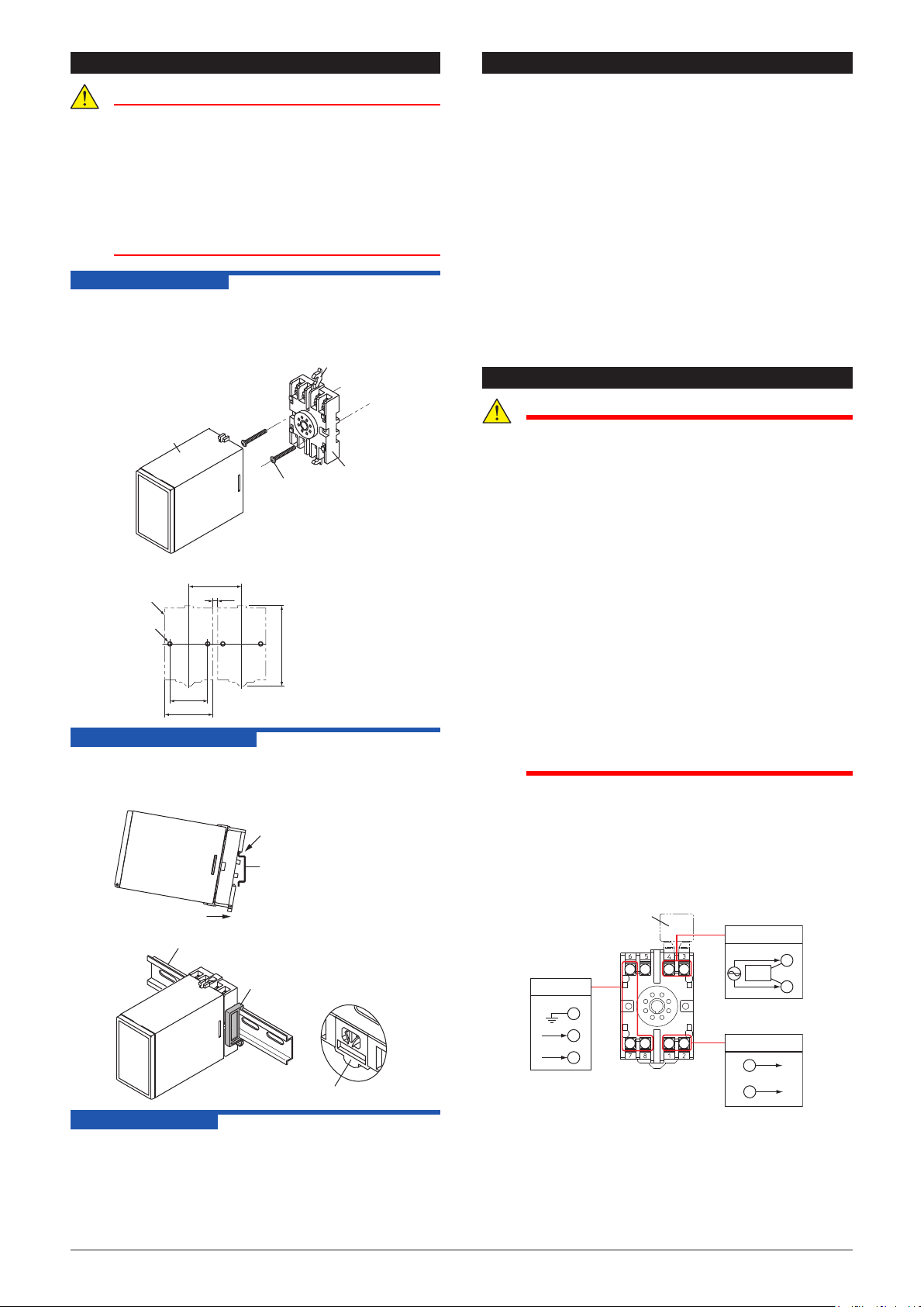
1.1 Wall Mounting
Remove the stoppers (top and bottom) from the product and pull
out the main unit from the socket. Fix the socket on the wall using
two M4 screws. Next, insert the main unit into the socket and
fasten the main unit with the stoppers (top and bottom).
5 or more
(51)
(85)
Socket
Socket
Mounting screws
Unit: mm
40±0.2
Pitch: 56 or more
2-ø4.5 or
2-M4
Note:
(1) More than 5 mm interval is
required for side-by-side
close mounting.
(2) Use the supplied spacer for
DIN rail mounting to keep 5
mm interval.
Main unit
1.2 DIN Rail Mounting
Insert a DIN rail into the upper part of the DIN rail groove on the
rear of the socket, and then slide the slide lock at the lower part of
the socket upwards until the socket is xed into position as shown
below.
Slide lock
Spacer
DIN rail
DIN rail
Fit into here
Push
1.3 Using a Duct
When using a wiring duct, install the duct at leaset 20 mm away
from the top and bottom faces of the main unit.
2. INSTALLATION LOCATIONS
• Avoid the following environments for installation locations:
Areas with vibrations, corrosive gases, dust, water, oil,
solvents, direct sunlight, radiation, a strong electric eld,
and/or a strong magnetic eld, direct radiant heat, wind,
temperature uctuation, 2000 m or more above sea level.
• If there is any risk of a surge being induced into the power
line and/or signal lines due to lightning or other factors, a
dedicated lightning arrester should be used as protection for
both this unit and a eld-installed device.
• Operating temperature/humidity range: 0 to 50°C (0 to 40°C
for multiple mounting)/5 to 90%RH (no condensation)
* If the previous model (style S3.xx earlier) is installed
together, the ambient temperature is 0 to 40°C.
• Continuous vibration: (at 5 to 9 Hz) Half amplitude of 3 mm or
less (at 9 to 150 Hz) 9.8m/s2 or less, 1 oct/min for 90 minutes
each in the three axis directions
• Impact: 98 m/s2 or less, 11 ms, 3 axes, 6 directions, 3 times
each
• Install in a place where rigidity is secured.
3. EXTERNAL WIRING
WARNING
●To avoid the risk of an electric shock, turn o the
power supply and use a tester or similar device to
ensure that no power is supplied to a cable to be
connected, before carrying out wiring work.
●Do not operate the product in the presence of
ammable or explosive gases or vapors. To do so is
highly dangerous.
●Use of the product ignoring the specications may
cause overheating or damage. Before turning on
the power, ensure the following:
•Power supply voltage and input signal value
applied to the product should meet the required
specications.
•The external wiring to the terminals and wiring to
ground are as specications.
●When disconnecting the main unit from the socket
with a live wire, it is necessary to install a CT
protector (CTP-5: sold separately) on the input
terminal of MCT7. However, do not leave the main
unit unattached from the socket for more than one
minute even with the CTP-5 installed. If the main
unit is removed from the socket without the CTP-
5 installed, high voltage will be generated on the
secondary side of the CT, which may cause burnout
of the CT and is very dangerous.
Wiring should be connected to the terminals on the socket
of the product. The terminals for external connections are of
M3.5 screws. Use crimp-on terminal lugs for connections to the
terminals.
• Recommended cables: A nominal cross-sectional area of
0.5 mm2or thicker for signal cables, and that of 1.25 mm2or
thicker for power cables.
Wiring Diagram
6 5 4 3
7 8 1 2
L+
N–
GND
6
7
8
3
4
A
±
CTP-5
+
–
2
1
Power Supply
Output
Input
2IM 77J04W02-01E 1st Edition


