manuals.online logo
Brands
  1. Home
  2. •
  3. Brands
  4. •
  5. YOKOGAWA
  6. •
  7. Measuring Instrument
  8. •
  9. YOKOGAWA 96065 User manual

YOKOGAWA 96065 User manual

User's
Manual
Checking the Package Contents
After receiving the product and opening the package, check the items described below. If the wrong
items have been delivered, if items are missing, or if there is a problem with the appearance of the
items, contact your nearest YOKOGAWA dealer.
Check that the product that you have received is the same product that you ordered.
For reference, the model name, suffix code, and specifications of the products are listed below.
Clamp-on Probe Accessories
Model Description Name Notes
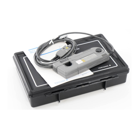
96065 Clamp-on Probe 1000 A Cable marker 6 pieces (3 x 2): For 96065
96066 Clamp-on Probe 3000 A Output cable For 96066
Accessory is not covered by warranty of this instrument.
* For products whose suffix code contains “Z,” an exclusive manual may be included.
Please read it along with the standard manual.
Accessories (Manuals)
Manual No.
Notes
IM 96065-01EN This manual.
IM 96065-92Z1 A manual for China.
PIM 113-01Z2 Contact information of Yokogawa offices worldwide is provided.
* The clamp-on probe comes with the these manuals. Please keep them in a safe place.
The “-EN” in the manual number is the language code.
Safety Precautions
This product is designed to be used by a person with specialized knowledge.
The general safety precautions described herein must be observed during all phases of operation.
If the instrument is used in a manner not specified in this manual, the protection provided by the
instrument may be impaired.
YOKOGAWA assumes no liability for the customer’s failure to comply with these requirements.
This manual is an essential part of the product; keep it in a safe place for future reference.
The following symbols are used on this instrument.
Warning: handle with care. Refer to the user’s manual or service manual.
This symbol appears on dangerous locations on the instrument which require special
instructions for proper handling or use. The same symbol appears in the corresponding
place in the manual to identify those instructions.
Indicates a Instrument with double or reinforced insulation.
Indicates that application around and removal from UNINSULATED HAZARDOUS LIVE
conductors, which may render arc discharge, electric shock, or electric burn, is prohibited.
Indicates alternating current.
French
Avertissement: À manipuler délicatement. Toujours se reporter aux manuels d'utilisation
et d'entretien. Ce symbole a été apposé aux endroits dangereux de l'instrument pour
lesquels des consignes spéciales d'utilisation ou de manipulation ont été émises. Le
même symbole apparaît à l'endroit correspondant du manuel pour identifier les consignes
qui s'y rapportent.
Équipement protégé par une double isolation ou une isolation renforcée.
Ne pas enserrer ou retirer de conducteurs NON ISOLÉS sous TENSION DANGEREUSE
prouvant entrainer un choc électrique, une brûlure, ou un arc électrique
Indique courant alternatif.
Failure to comply with the precautions below could lead to injury or death or damage to the instrument.
WARNING
• This instrument is designed exclusively for the CW500 or the like products.
Do not use the instrument for devices other than the specified CW500 products.
• Do not use the instrument if there is a problem with its physical appearance.
• Never make measurement on a circuit in which the electrical potential exceeds
AC 600 V in the measurement category III using 96066.
• Never make measurement on a circuit in which the electrical potential exceeds
AC 300 V in the measurement category IV and AC 600 V in the measurement
category III using 96065.
• Do not operate the instrument in the presence of flammable gasses or vapors.
Doing so is extremely dangerous.
• Do not make measurement when thunder rumbling. If the instrument is in
use, stop the measurement immediately and remove the instrument from the
measured object.
• Do not use the instrument if the instrument or your hands are wet.
Otherwise, electrical shock accident may occur.
• Use insulated protective gears, such as insulated gloves, for your safety when
using this instrument.
• Only qualified YOKOGAWA personnel may remove the covers and disassemble
or alter the instrument.
•
Do not install or use the instrument outdoors or in locations subject to rain or water.
CAUTION
• Do not step on or pinch the cord to prevent the jacket of cord from being
damaged.
• The output connector shall be removed or connected without clamping a
conductor. Otherwise, it may cause a failure.
•
Do not expose the instrument to direct sunlight, high temperatures, humidity or dew.
•
Never give shocks, such as vibration or drop, which may damage the instrument.
This manual describes the safety precautions for using the clamp-on probe and the clamp-on
probe specifications. For details on its handling procedure, see the user’s manual of the measuring
instrument that the clamp-on probe will be used with.
5th Edition : March 2021 (YMI)
All Rights Reserved, Copyright © 2015, Yokogawa Test & Measurement Corporation
Printed in Japan
IM 96065-01EN
5th Edition
IM 96065-01EN
• Use a damp cloth and detergent for cleaning the instrument. Do not use
abrasives or solvents
• This clamp sensor is not designed to be dust or waterproof. Do not use it dusty
places or where the clamp sensor is likely to be wet. It may cause troubles on
the clamp sensor.
• Never pinch foreign matters or give vibrations at the jointed parts of this
clamp sensor. Otherwise, matching area of Jaws may be damaged and cause
influences on the measurements.
• Do not bend or pull the root of the cable in order to prevent breaks in the cable.
• Never apply the current exceeding the measuring range for a long time. It may
damage the clamp sensor.
• Never connect/remove the connectors while connected devices are on or
clamping onto the conductor under test. Otherwise, the connected devices or
clamp sensors may be damaged.
• Accurate measurement may not be obtained in the vicinity of strong magnetic
fields such as transformers, high-current circuits or wireless machines.
Operating Environment Limitations
The 96065 is classified as Class A (for use in industrial environments).
Operation of this product in a residential area may cause radio interference,
in which case the user will be required to correct the interference.
French
AVERTISSEMENT
• L’instrument est exclusivement concu pour les produits le CW500.
Ne pas utiliser l’instrument pour d’autres appareils que les produits CW500
indiques.
• Ne pas utiliser l'instrument si son intégrité physique semble être compromise.
• Ne jamais effectuer de mesure de l'intensité sur un circuit dans lequel le
potentiel électrique dépasse 600 V CA dans la catégorie de mesure III utilisant
96066.
• Ne jamais effectuer de mesure de l'intensité sur un circuit dans lequel le
potentiel électrique dépasse 300 V CA dans la catégorie de mesure IV et 600 V
CA dans la catégorie de mesure III utilisant 96065.
• Ne pas utiliser l'instrument en présence de gaz ou de vapeurs inflammables.
Cela pourrait être extrêmement dangereux.
• Ne pas effectuer de mesure lorsque le tonnerre gronde. Si l'instrument est en
cours d'utilisation, arrêter immédiatement la mesure et retirer l'instrument de
l'objet mesuré.
• Ne pas utiliser l'instrument s'il est mouillé ou si vos mains sont mouillées.
Sinon, un choc électrique peut se produire.
• Utiliser des équipements de protection isolés, tels que des gants isolés, pour
votre sécurité lors de l'utilisation de cet instrument.
• Seul le personnel YOKOGAWA qualifié est habilité à retirer le capot et à
démonter ou modifier l'instrument. Certains composants à l'intérieur de
l'instrument sont à haute tension et par conséquent, représentent un danger.
• Ne pas installer, ni utiliser l’instrument à l’extérieur ou dans des lieux exposés à
la pluie ou à l’eau.
ATTENTION
• Ne pas marcher sur le cordon et ne pas le pincer afin d'éviter que la gaine du
cordon ne soit endommagée.
• Le connecteur de sortie doit être retiré ou raccordé sans serrer un conducteur.
Si cette condition n'est pas respectée, cela risque de générer une défaillance.
• Ne pas exposer l'instrument aux rayons directs du soleil, à des températures
élevées, à l'humidité ou à la rosée.
• Ne jamais faire de chocs, tels que des vibrations ou des chutes, qui risqueraient
d'endommager l'instrument.
• Utiliser un chiffon humide et du détergent pour nettoyant l'instrument. Ne pas
utiliser de produits abrasifs ou de solvants.
• Ce capteur à serrer n'est pas conçu pour être recouvert de poussière et
n'est pas résistant à l'eau. Ne pas l'utiliser dans des endroits poussiéreux ou
dans des endroits où le capteur à serrer risque d'être mouillé. Cela risque de
perturber le fonctionnement du capteur à serrer.
• Ne jamais pincer de matières étrangères ou faire de vibrations au niveau des
pièces articulées de ce capteur à serrer. En effet, cela risquerait d'endommager
la zone correspondante des mâchoires et d'avoir des impacts sur les mesures.
• Ne pas plier ou tirer la base du câble afin d'éviter qu'il ne se casse.
• Ne jamais appliquer un intensité dépassant la plage de mesure pendant une
longue période. Cela risque d'endommager le capteur à serrer.
• Ne jamais raccorder ou retirer les connecteurs lorsque les appareils raccordés
sont allumés ou que le serrage sur le conducteur est en cours de test. En effet,
cela risquerait d'endommager les appareils reliés ou les capteurs à serrer.
• Il est impossible d'obtenir une mesure précise à proximité de champs
magnétiques puissants tels que des transformateurs, des circuits à haute
intensité ou des machines sans fil.
Limitations relatives à l'environnement opérationnel
Le 96065 est classé dans classe A (pour utilisation dans des environnements
industriels). L’utilisation de ce produit dans un zone résidentielle peut entraîner
une interférence radio que l’utilisateur sera tenu de rectifier.
Conventions Used in This Manual
The notes and cautions in this manual are categorized using the following symbols.
Improper handling or use can lead to injury to the user or damage to the instrument. This
symbol appears on the instrument to indicate that the user must refer to the user’s manual
for special instructions. The same symbol appears in the corresponding place in the user’s
manual to identify those instructions. In the manual, the symbol is used in conjunction with
the word “WARNING” or “CAUTION.”
Une manipulation ou une utilisation incorrectes risquent de blesser l’utilisateur ou
d’endommager l’instrument. Ce symbole apparaît sur l’instrument pour indiquer à
l’utilisateur qu’il doit se reporter au manuel de l’utilisateur afin d’y lire les instructions
spécifiques correspondantes. Ce même symbole apparaît à la section correspondante du
manuel de l’utilisateur pour signaler lesdites instructions. Dans le manuel de l’utilisateur,
ce symbole est accompagné des termes AVERTISSEMENT et ATTENTION.
WARNING
Calls attention to actions or conditions that could cause serious or fatal injury to the user,
and precautions that can be taken to prevent such occurrences.
AVERTISSEMENT
Attire l’attention sur des gestes ou des conditions susceptibles de provoquer des
blessures graves (voire mortelles), et sur les précautions de sécurité pouvant
prévenir de tels accidents.
CAUTION Describes precautions that should be observed to prevent minor or moderate injury,
or damage to the instrument.
ATTENTION Attire l’attention sur des gestes ou des conditions susceptibles de provoquer des
blessures légères ou d’endommager l’instrument ou les données de l’utilisateur,
et sur les précautions de sécurité susceptibles de prévenir de tels accidents.
Note Calls attention to information that is important for proper operation of the instrument.
96065, 96066
Clamp-on Probe
Waste Electrical and Electronic Equipment
Waste Electrical and Electronic Equipment (WEEE)
(This directive is valid only in the EU.)
This product complies with the WEEE Directive marking requirement. This marking
indicates that you must not discard this electrical/electronic product in domestic
household waste.
Product Category
With reference to the equipment types in the WEEE directive, this product is classified
as a “Monitoring and control instruments” product.
Do not dispose in domestic household waste. When disposing products in the EU,
contact your local Yokogawa office in Europe.
Authorized Representative in the EEA
Yokogawa Europe B. V. is Authorized Representative of Yokogawa Test & Measurement Corporation
in the EEA for this Product. To contact Yokogawa Europe B.V., see the separate list of worldwide
contacts, PIM 113-01Z2.
Disposal
When disposing of this instrument, follow the laws and ordinances of the country or region where the
product will be disposed of.
Measurement Category:
To ensure safe operation of measuring instruments, IEC 61010 establishes safety standards for various
electrical environments, categorized as O to .IV, and called measurement categories.
Measurement category O (Other)
Applies to measurement of circuits that are not directly connected to a main power source.
This category applies to measurement of secondary electric circuits in equipment across a transformer.
Measurement category II
Applies to measurement of circuits, such as household electric appliances and portable electric
tools, that are connected to low-voltage installations.
Measurement category III
Applies to measurement of facility circuits, such as distribution boards and circuit breakers.
Measurement category IV
Applies to measurement of power source circuits, such as entrance cables to buildings and cable
systems, for low-voltage installations.
Names of Parts
Clamp sensor
Cable
Power
indicator
Output cable
Output terminal
Joint part of the sensor
RANGE button
Joint part of the sensor
Output terminal
Output cable
Circuit box
Cable
96065 96066
Clamp sensor
Circuit
box
Din Plug Pin Assignment
96065 96066
5
3
1
6
4
2
1: 3.0 to 5.5 V
2: -5.5 V to -3.0 V
3: COM(Output Lo)
4: NC
5: Output(Hi)
6: NC
Match the mark
under CH No. and arrow
mark on the output
cable, and connect the
cable.
Output signal
Power supply 5
3
1
6
4
2
1: NC 2: 2.7 V to 5.5 V
3: NC 4: COM (Output Lo)
5: NC 6: Output (Hi)
5
3
1
6
4
21: 2.7 V to 5.5 V 2: NC
3: COM (Output Lo) 4: NC
5: Output (Hi) 6: NC
Output terminal
* This instrument is supplied power via an output cable. Power
supply of 2.7 to 5.5 V (200 mVA) is required between 1 and 3 of
the output terminal and between 2 and 4 of the output connector.
* Resistance between 3 and 6 of the output terminal and between
4 and 5 of the output connector is as follows.
300 A Range: 910 kΩ, 1000 A Range: 360 kΩ,
3000 A Range: 510 kΩ
(Resistance cannot be measured while the instrument is powered
off status.)
* This clamp-on probe is
supplied power via
an output cable.
Power supply of +3.0
to +5.5 V is required
between 1 and 3 of
the output terminal and
-3.0 to -5.5 V is
required between
2 and 3 of the output
terminal.
Output terminal of
the circuit box
Specifications
Model 96065 96066
Measureable conductor
size Max. φ110 mm Max. φ150 mm
Measurment range AC 0 to 1000 Arms (1850 Apeak) 300 A range: 30 to 300 Arms (424 Apeak)
1000 A range: 100 to 1000 Arms (1414 Apeak)
3000 A range: 300 to 3000 Arms (4243 Apeak)
Output voltage AC 0 to 500 mVrms (0.5 mV/A) 300 A range: AC 0 to 500 mVrms (1.67 mV/A)
1000 A range: AC 0 to 500 mVrms (0.5 mV/A)
3000 A range: AC 0 to 500 mVrms (0.167 mV/A)
Accuracy
Amplitude
(sine wave input)
±0.8% rdg ±0.2 mV (45 Hz to 65 Hz)
±1.5% rdg ±0.4 mV (40 Hz to 1 kHz)
±1.0% rdg (45 Hz to 66 Hz)
(measuring at center of the sensor))
Accuracy
Phase
(sine wave input)
±2.0° or less (45 Hz to 65 Hz)
±3.0° or less (40 Hz to 1 kHz)
±1.0° or less
(each measurement range, 45 Hz to 65 Hz)
Temperature and humidity
range (guaranteed
accuracy)
23 ±5°C, 85%RH or less (no condensation)
Current consumption 2 mA max. (at power supply ±5 V) 15 mA (at power supply 3 V)
Rated voltage between
circuit and ground AC 600 Vrms max
Operating temperature
and humidity range -10 to 50°C, 85% RH or less
(no condensation) 0 to 50°C, 85% RH or less
(no condensation)
Storage temperature
and humidity range -20 to 60°C, 85% RH or less (no condensation)
Temperature coefficient 0.03% rdg./°C (-10 to 50°C) In the range of 0 to 50°C and the amount of
change from 23°C is ±2.5% rdg or less
Maximum allowable input AC 1300 Arms AC 3600 Arms(45 Hz to 65 Hz)
Output impedance 100 Ω or less
Influence of the conductor
location Within ±1.5% rdg Within ±5% rdg
Influence of the external
magnetic field Current that flows through the
conductor ±1.0% rdg or less when
separated by a distance of D/4
(27 mm) from the conductor
Current that flows through the conductor ±2.0%
rdg or less when separated by a distance of D/4
(37.5 mm) from the conductor
Withstand voltage AC 5.4 kVrms / 5 seconds Between circuit and sensor.
Environmental condition Altitude up to 2000 m, in-door use
Recommended calibration
period 1 year
Dimension 24 (W) × 65 (H) × 22 (D) mm
(excluding projections) 61 (W) × 111 (H) × 37 (D) mm
(excluding projections)
Weight Approx. 170 g Approx. 950 g
Cable length Clamp sensor – circuit box:
approx. 2.7 m
Circuit box – output terminal:
approx. 0.2 m
Clamp sensor – circuit box: approx. 2 m
Circuit box – output terminal: approx. 1 m
Output terminal MINI DIN 6PIN
Accessory User's manual, Cable marker User's manual, Output cable
Safety standards Compliant standards:
EN 61010-1, EN 61010-2-032
Measurement category III
(rated voltage between circuit and
ground: 600 Vrms)
Measurement category IV
(rated voltage between circuit and
ground: 300 Vrms)
Pollution degree 2*
Compliant standards:
EN 61010-1, EN 61010-2-032
Measurement category III
(rated voltage between circuit and ground:
600Vrms)
Pollution degree 2*
EMC Compliant standards:
EN 61326-1 Class A
EMC standards of Australia and
New Zealand EN 55011 Class A,
Group 1
Compliant standards:
EN 61326-1 ClassB, EN 61326-2-2
EMC standards of Australia and New Zealand
EN 55011 Class B, Group 1
Korea Electromagnetic Conformity Standard ( 한국 전자파적합성기준 )
The 96065 is a Class A (for industrial environment) product. Operation of this product
in a residential area may cause radio interference in which case the user will be
required to correct the interference.
Environmental standards EU RoHS Directive compliant
* Pollution Degree applies to the degree of adhesion of a solid, liquid, or gas that deteriorates withstand voltage
or surface resistivity. Pollution degree 2 applies to normal indoor atmospheres (with only non-conductive
pollution).
External Dimensions
65
24 22
Ø8
110
96065 96066
111
φ14
150
61
φ5
37 Unit: mm
Unless otherwise specified, tolerances are ±3%
(however, tolerances are ±0.3 mm when below 10 mm).
Measurement
CAUTION
• When making current measurements, keep the clamp sensor fully closed.
Otherwise, accurate measurements cannot be taken.
• When disconnecting the output terminal from the measuring instrument, do so
by removing the plug first and not by pulling the cord.
• Clamp onto one conductor only; measurements cannot be made when
clamping single-phase (2-wire) or three-phase (3-wire) at the same time.
Measurement procedures
1.
Connect the output connector to the Input terminal of the measuring instrument.
2.
Power on the measuring instrument.
3.
Disconnect the joint according to the following figure.
Pull out the sensor
Pull down the lock
Joint
Sensor
Lock
Cable
Joint Sensor
Push
Pull out the sensor
96065 96066
4.
Clamp onto one conductor under the test. When connecting the sensor with the power meter
(CW500 etc.), check the direction of the guide arrow mark indicating the current flowing direction
marked on the Joint of the clamp sensor to make the phase of the current under test and output
voltage synchronized.
96065 96066
Load
Source
Guide arrow mark
Source Load
Guide arrow mark
Joint fixing hole
Insert pins in the Joint
fixing hole to ensure a
firm connection.
Use non-conductive
pin for fixing the Joint
in order to avoid
getting an electrical
shock.
Reference test position of the
conductor for 96065 Reference test position of the
conductor for 96066
Clamp onto one conductor only.
OK NG
5.
Confirm that the Joint on the Clamp sensor is firmly locked.
6.
Select any desirable range (300A/ 1000A/ 3000A) with the RANGE button. When powering off
the instrument once and powering on again, the range will be the one selected before powering
off the instrument.
IM 96065-01EN

This manual suits for next models

1

Other YOKOGAWA Measuring Instrument manuals

YOKOGAWA IR400 series User manual

YOKOGAWA

YOKOGAWA IR400 series User manual

YOKOGAWA PH71 User manual

YOKOGAWA

YOKOGAWA PH71 User manual

YOKOGAWA 99025 User manual

YOKOGAWA

YOKOGAWA 99025 User manual

YOKOGAWA AQ6370C User manual

YOKOGAWA

YOKOGAWA AQ6370C User manual

YOKOGAWA 2100A series User manual

YOKOGAWA

YOKOGAWA 2100A series User manual

YOKOGAWA AR-SA User manual

YOKOGAWA

YOKOGAWA AR-SA User manual

YOKOGAWA TDLS200 User manual

YOKOGAWA

YOKOGAWA TDLS200 User manual

YOKOGAWA IR800G User manual

YOKOGAWA

YOKOGAWA IR800G User manual

YOKOGAWA 2014 00 User manual

YOKOGAWA

YOKOGAWA 2014 00 User manual

YOKOGAWA AQ7277 User manual

YOKOGAWA

YOKOGAWA AQ7277 User manual

YOKOGAWA 765501 User manual

YOKOGAWA

YOKOGAWA 765501 User manual

YOKOGAWA WT1801E User manual

YOKOGAWA

YOKOGAWA WT1801E User manual

YOKOGAWA AQ6375E User manual

YOKOGAWA

YOKOGAWA AQ6375E User manual

YOKOGAWA 322610 User manual

YOKOGAWA

YOKOGAWA 322610 User manual

YOKOGAWA VigilantPlant mR20000 User manual

YOKOGAWA

YOKOGAWA VigilantPlant mR20000 User manual

YOKOGAWA YPP6870 User manual

YOKOGAWA

YOKOGAWA YPP6870 User manual

YOKOGAWA WT1600FC User manual

YOKOGAWA

YOKOGAWA WT1600FC User manual

YOKOGAWA CW140 User manual

YOKOGAWA

YOKOGAWA CW140 User manual

YOKOGAWA PBL5000 User manual

YOKOGAWA

YOKOGAWA PBL5000 User manual

YOKOGAWA YPP6060 User manual

YOKOGAWA

YOKOGAWA YPP6060 User manual

YOKOGAWA DAQSTATION DX100 Manual

YOKOGAWA

YOKOGAWA DAQSTATION DX100 Manual

YOKOGAWA 701949 User manual

YOKOGAWA

YOKOGAWA 701949 User manual

YOKOGAWA wt1600 User manual

YOKOGAWA

YOKOGAWA wt1600 User manual

YOKOGAWA TA720 User manual

YOKOGAWA

YOKOGAWA TA720 User manual

Popular Measuring Instrument manuals by other brands

Rhopoint Optimap PSD operating instructions

Rhopoint

Rhopoint Optimap PSD operating instructions

Endress+Hauser Liquiphant S FDL60 Functional safety manual

Endress+Hauser

Endress+Hauser Liquiphant S FDL60 Functional safety manual

Kobold DTK operating instructions

Kobold

Kobold DTK operating instructions

ThermoWorks IRT-2 Infrared operating instructions

ThermoWorks

ThermoWorks IRT-2 Infrared operating instructions

Kimo HD110 user manual

Kimo

Kimo HD110 user manual

Sierra MaxTrak 180 Series instruction manual

Sierra

Sierra MaxTrak 180 Series instruction manual

GE AutoSigma 3000 DL Technical Reference, Operating Manual

GE

GE AutoSigma 3000 DL Technical Reference, Operating Manual

Endress+Hauser Levelflex M FMP41C operating instructions

Endress+Hauser

Endress+Hauser Levelflex M FMP41C operating instructions

Tecsis TM1 Series operating instructions

Tecsis

Tecsis TM1 Series operating instructions

Kaysun DTS634 Operation manual

Kaysun

Kaysun DTS634 Operation manual

Zuzi 4251 manual

Zuzi

Zuzi 4251 manual

Johnson Level & Tool LDM330 instruction manual

Johnson Level & Tool

Johnson Level & Tool LDM330 instruction manual

RFL 904 instructions

RFL

RFL 904 instructions

PRECISION DIGITAL PD6720 Series instruction manual

PRECISION DIGITAL

PRECISION DIGITAL PD6720 Series instruction manual

CeYeKo PDIS01 user manual

CeYeKo

CeYeKo PDIS01 user manual

Metabo Elektra Beckum RF 480 operating instructions

Metabo

Metabo Elektra Beckum RF 480 operating instructions

Sym uwms-01 user manual

Sym

Sym uwms-01 user manual

Murideo Fresco SIX-A user manual

Murideo

Murideo Fresco SIX-A user manual

manuals.online logo
manuals.online logoBrands
  • About & Mission
  • Contact us
  • Privacy Policy
  • Terms and Conditions

Copyright 2025 Manuals.Online. All Rights Reserved.