YOOSEE KW02 User manual

User manual
Smart Video Doorbell
The smart doorbell can be connected via WiFi or cat5e LAN Cable.
When the visitor presses the button on the doorbell, your smart device interacts
with the doorbell:
via real time video and full duplex talk
take photos and record videos that save directly to your smart device or
MicroSD card of doorbell
activates your indoor chime with preset melodies and volume control
Further features include unlocking via smart device, as well as RFID card access.
1 administrator user and up to 10 guest users connect one doorbell.
o
o
o
1

2
Volume
DC12~36V,
AC 8~24V
NC COM NO
Access port
Press the “Reset” button
3seconds to reset
RJ45 port
Set ID card/ unlock delay time
ID: 008641
WiFi Doorbell
1 Specifications
WiFi 802.11 b/g/n or connected to a wired network
Full duplex talk
IR CUT no color deviation, B/W night vision within 3meters
Night vision
150 Horizontal angle
View Angle
Resolution
1 megapixels
Network
Motion detection, PIR alarm, Tamper alarm
Alarm
Push message to smart phone, send pic to the setting mailPush
DC12~36V, AC 8~24V or POE power by connect POE injector
Power adapter
RTSP
25 Frame HD(1080*720), SD(640*360)
Frame rate
Micro SD card without limiting capacity
External Memory
Manual, Record alarm, Record timerRecord mode
Talk
2 Technical Parts
Music
Light
93mm
145mm
23mm
39mm
Swipe area
Photoresistor
IR Leds
PIR
sensor
Speaker
Mic
Rain cover
Camera
Call button
The RTSP password will be set by APP, RTSP major stream:
rtsp://IPadr:554/onvif1, minor stream: rtsp://IPadr:554/onvif2

3
4 Network Connection and Power Supply
The smart doorbell can be powered and connected to the network in 3 ways, depending
on location of power source and strength of internet connection.
We would recommend that the LAN cable configuration is used if WiFi is not strong enough,
ie the distance between the doorbell and the router is greater than 10 meters.
Power: Connect DC cable to doorbell and then to the power adaptor or AC transformer
and then to mains.
Internet: The doorbell can be connected via LAN Cable. See pic A
Power: Same as 4.1.
Internet: The doorbell can be connected via WiFi. See pic A
Power: Connect the doorbell via LAN Cable (cable not supplied) at RJ45 port to
POE injector and into Router.
Internet: The doorbell can only be connected via LAN Cable if using this configuration.
4.1
4.2
4.3
Unlock control Indoor chime
Remote control MicroSD card
3 Accessories
12V Power adapter DC cable
POE injector Screwdriver Screws and stopper Adhesive tape
Unlock wiring Access wiring
Optional
5* Blue User cards
1* Red Delete card
1* Yellow Add card
2* Connector
ID: 008641
WiFi Doorbell
A
Length Max 50meters
B
AC 8~24V or DC 12~36V
DC 12V

5.2 Wiring diagram of connect double power adapter, POE can replace the power adapter
Please check the specification of electric current for existing electronic lock and
access control, as the power charger supplied is for 1A/12V supply.
5.1 Wiring diagram of connect single power adapter
Power on wiring diagram Power off wiring diagram
NC
3A
COM NO Exit
NC
2A
1A
COM NO Exit
DC Cable
NC
2A
1A
COM NO Exit
DC Cable
Position
1S 4S 8S 16SDelay time
NO
COM
NC
Pair button
-
1S4S8S
12V
Pair light
5.3 Wiring diagram if connect unlock controller (optional)
COM connections are same, Different are connected NO or NC.
Power on wiring diagram Power off wiring diagram
Delay time
30 meters
10 meters
30 meters
5 Unlock settings
NO
COM
NC
12V
-
2A
NO
COM
NC
12V
-
2A
4
NC COM NO Exit
3A

5
Default
oNote that you cannot delete a user card if the card has not been added
or deleted already
.
Likewise you cannot add a user card,if the card has been added already
to another RFID access point
.
If you hear 3 beeps, then there is either an issue with the card or a mistake
in the operation
.
o
o
6 Pairing of Devices
Setting
7.2 Add users and remove users
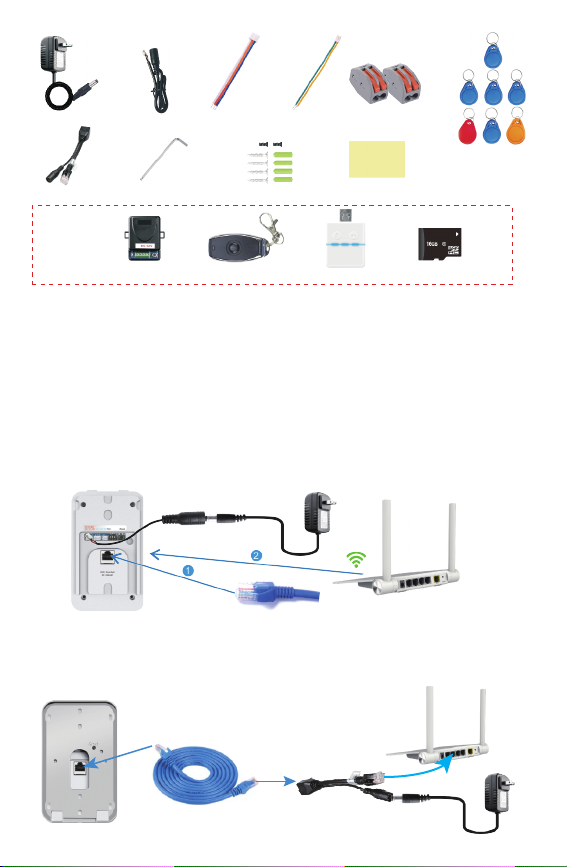
Turn the power to the doorbell off, by removing power and LAN cable if applicable,
and reset the switches to default (all 3 switches to off/bottom).Connect the doorbell
power on again.
Swipe yellow add card, and then light will illuminate and beep. Then swipe blue user
card to activate, then light will illuminate and beep to confirm.
To remove the user, swipe the red delete card, followed by the applicable blue user card.
6.1 Pair indoor chime with smart doorbell
Ensure that indoor chime is connected to power, either in USB port or with USB adaptor
through mains. Ensure that the Smart doorbell is powered and connected to router.
Press the “volume” button of indoor chime and release until light goes out,
then press the “call” button of doorbell, the light of the indoor chime will flash once,
then press the “call” button of the doorbell again, and the indoor chime will flash several
times. This means that the pairing is successful.
To unpair, press the “volume” button on the indoor chime for longer than 3 seconds for
the light to go out.
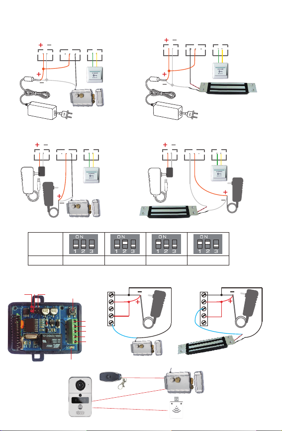
6.2 Pair unlock control with smart doorbell
Ensure that both the unlock control and doorbell are connected to power and router.
Press the “call” button of the doorbell, and then the smart device will run a call as normal
with the app. Open the call in the app and enter talk state. Press the “pair” button on the
unlock control and the “unlock” button on the app on your smart device. The pair light will
flash, then press the “pair” button again on the unlock control and the light will stop flashing,
then press the “unlock” button in the app again and the light will flash several times.
This means that the pairing is successful.
To unpair, press the “pair” button on the unlock control for longer than 3 seconds for the
light to go out.
6.3 Pair remote control with unlock control
Ensure that the unlock control is connected to power and doorbell.
Press the “pair” button on the unlock control, and the “pair” light will flash one time,
then press the “unlock” button on the remote control, and the “pair” light will flash
continuously, then press the “pair” button on the unlock control and the light stops flashing,
then press the “unlock” button on the remote control and the pair light will flash several
times. This means that the pairing is successful.
Troubleshooting:
7 RFID Card Settings
7.1 Setting the Management Card
The smart doorbell is supplied with 1x yellow add card,
1x red delete card and 5x blue user cards.
Ensure that the 3 switches are all set to off (bottom position).
Then turn off power of Smart doorbell by removing power and if applicable LAN
cable, and set the position 3 switch to ON and then turn power of doorbell on again.
You are now in management mode and the red and blue light will illuminate on
RFID front panel. Swipe the yellow add card and then the doorbell will beep to
confirm. Then swipe the red delete card and the doorbell will beep and then
the light will go off.

1.3~1.6 meters
1
3meters
150
Horizontal angle
1
3
2
6
We recommend that you carefully consider the permanent location of your
Smart Doorbell, avoiding direct sunlight as well as wind and rain.
The doorbell is supplied with 4x screws and plugs, double sided tape and 2x
small tamper alarm screws. 8.1 Should you not be able to use screws
into walls or panels, double sided tape is
applied to the housing. See pic A
86 box
2
8 Installation of Smart Doorbell
8.3 Use the 2 screws to secure the housing into a an existing structure - see pic C
8.2 Use the 4 screws in the four corners of the housing to attach to wall,
arrow 4 for location of screw to attach doorbell to housing - see pic B.
A
B
C
3
1
4
2
Double faced
adhesive tape
4
8.4 Install on the existing doorbell location,connect the AC Transformer.
Before you start, you must turn off the circuit breaker for safety purposes.
Remove existing doorbell from location and disconnect the wires. - see pic C
°
D

The Yoosee app can be freely downloaded for Android and iOS operating systems.
9.1 Download window software CMS from http://www.yoosee.co
9.2 Search “Yoosee” from APP store or Google Play Store according to phone system
9.3 Scan QR code to download and install
9 App Download- Yoosee
1 WiFi connection
7
10.2 Connect device to APP
10.1 Register & Login
Run the Yoosee app, create a user for yourself
on the app.
You can set yourself up as user either via your
email address or phone number, follow prompts
to create a password.
Click “Forgot password?” to reset your login
password.
User can login if have wechat or Line account.
10 Connecting to Video doorbell
Ensure that the doorbell is connected to power and the router’s DHCP is on. WiFi
connection include Fast networking (AP connection) and smartlink . Fast networking
is recommended.
Yoosee
iOS Google Play

Select Fast networking→enter the WiFi password then tap <Next>→ Tap<Hearing
the sound of “Du Du”>iOS APP will tap“Connect the AP hot spot” →select hotpost
GW_AP_XXX that no password→return Yoosee APP, Wait less than 10 seconds
then Name the device, Enter the name then tap<Confirmed, Check my device>.
Connect the LAN cable into the RJ45 port and into your router port.
Tap <Wired connection>, Mobile phone of User and device in the same LAN,
Tap <Next>, user will find one device display the list. tap + to add,wait for
1~2 minutes until finish the <Bind device>
2 Wired connection
The first user to add a doorbell is the administrator. tap Share icon to enter
3 share modes
1 Enter the account(email or mobile phone) of share user then tap <Share>
2Face-to-face sharing will make a QR code. Other user scan the QR
code to add the device. User tap <Scan it>
3Shaing on social media will make a link. administrator can send the link by
Message,Mail or other social tools such as Wechat, whatsapp.
Note: After the shared user connect the doorbell, Administrator tap <Share>
to setting the Permission configuration for the shared user.
3 Share user and Sharing management
8
1Tap the shared user
2 Tap <Configure> to setting the
Permission configuration, Tap
<Delete visitor> to delete the user.
3Set permissions for shared users,
including five options in the left table

10.3 Unbind devices
To unbind the doorbell from app, you can long press thumbnail of device interface
and confirm delete or unbind.
Slide right image of device in iOS app to display <Delete> and confirm delete.
9
11 Introduction of Device Interface
2 Message Tab
3 Image Tab
The message tab lists the time and date of visitor calls and alarms, with the
most recent appearing on the top of the log.
1 Device Tab
Note that the doorbell is only active if status is online. If doorbell is offline, it is because
either the doorbell is not connected to power or there is not network connection
between doorbell and your router.
4 My Tab Account information
General settings
About
User can bind email, Phone, modify login password, logout.
Whether automatic start for Android APP.
Whether to turned off sound automatically when monitoring
Setting the resolution is in default when monitoring.
Quick set the alert mode enable the receive the alarm.
Whether to start record video automatically when alarming.
APP description and current version information
Notification center
User can receive the share information here, Tap to
connect device
Help and feedback
Users can learn more about this device and APP.
Edit the device name Device status
On Guard
Disable will can not receive alarm
List of captured photos and videos, User can view and delete here.

Ensure that the time and time zone are set
to correct.
PAL or NTSC are selected,
Talk volume of video doorbell can be adjusted
Video quality include HD, SD, LD for Playback
file in MicroSD
Time settings
Picture and sound
Firmware update:
Tap <Settings>enter “Settings”
Alarm settings
Please confirm whether update if there is new firmware.
Network settings: Changing the connected network of doorbell.
Record settings
There are 3 modes of recording.
o
o
o
oBuzzer: 1, 2,3 Minutes or off.
oReceive alarm prompt:
User will not receive call from visitor,Motion detection or PIR detection if disabled.
Alarm email: Setting the mail to receive the screenshot after alarm trigger.
Human infrared detection:
This is enabled by default, which PIR detects within 3 meters of doorbell
Motion detection:
Enable the motion detection, User can set the sensitivity of motion detection.
<
10
RTSP settings: Setting the password when connecting to RTSP application.
oRecord alarm
Alarm to be activated on PIR detection,
motion detection, tamper alarm, call.
Pre-record increase video recording by 10 seconds before alarm trigger.
oRecord timer
Choose a period of time to record, video files are saved in the SD card.
oRecord manually
Start the recording when enabled, end the recording when disabled.
Tap Device ID will list Device ID, Device name,
Firmware version, LAN IP, Mac address.
5 Settings

11
12 Push Notification
When visitor calls, alarms, PIR and motion detections, the iOS device receives a push
notification when working (Pic A) or standby mode (Pic B).
now
Saturday, July 9
100%
Front door: You have a vistor
Answer Hang up
Yoosee
KBell
A
B
Front door: You have a vistor
HD= 1080*720
SD= 640*360
LD= 320*180
Record
Screenshot
Mute/Unmute
Unlock
Switch to full screen
Full duplex talk
Will not receive the
call and alarm after Unbind
Yoosee
Tap <Playback> enter “Playback”,
Pls insert the MicroSD to the doorbell.
So the MicroSD will record after
alarm trigger.
Click this you will view the video files
for the day and earlier
Screenshot
6 Playback

Save
CMS config
System info
Param
Close
Connect all of device automatically
Cycle Record Open
D:\CMS files\
File save path Brower
Reserve space
1024
MB
Record time for package
60
Min
Close
Auto start record when monitoring
Alarm trigger
Close
Auto Login
Render mode DIRECTDRAW
Auto
Monitor
Close
Message notification
13 Windows software introduction
Manual add device
Mute Last/Next Page
Full screen
Multiple windows
PlaybackPreview Log Settings Lock screen
Click , click
av files to mp4 files;
convert the
Enter settings user can modify the File save path of video, whether Cycle recode, Auto start record when
monitoring, Connect all devices automatically, Render mode, Monitor, Auto Login, Message notification.
Click “Manual add device” to add device if can not find
devices automatically, input devcie information to add.
Click << if remove the device.
Windows Client CMS default account is admin, password is blank, can logon by the
username and password of the app. Onvif connects NVR can be realized a large recording.
Device manager
Device added
Device name
Devie ID Group mame
Add share advice Exit
Type IP
Device ID Version
NO.
Device recently
NO.
Converting files to MP4
Save path
Start
NO. Size
Path Progress
Device All device
Stop
D:\CMS files\ Brower
Open
Manual add advice
Right-click on the selected device,
user can Intercom, Capture, Start Record.
Save
CMS config
System info
Param
Pop video
Audition
Buzzer
buzzer_02
Alarm trigger
5 s
Click <Alarm trigger>, Users have more options
to set the time to show the screen after alarm
trigger
Intercom
Capture
Start Record
Smooth
Standard definition
High definition
Full Screen
12
Table of contents