York International ZM Series User manual

Installation Manual
R-410A
ZM SERIES
10-12 Ton
50 Hertz
5703827-XIM-A-0319
Table of contents
General . . . . . . . . . . . . . . . . . . . . . . . . . . . . . . . . . . . . . . . . . . . . . . . . . . . . . . . . . . . . . . . . . . . . . . . . . . . . . . . . . . . . . . . . . . . . . . . . 3
Installation . . . . . . . . . . . . . . . . . . . . . . . . . . . . . . . . . . . . . . . . . . . . . . . . . . . . . . . . . . . . . . . . . . . . . . . . . . . . . . . . . . . . . . . . . . . . . . 7
Preceding installation . . . . . . . . . . . . . . . . . . . . . . . . . . . . . . . . . . . . . . . . . . . . . . . . . . . . . . . . . . . . . . . . . . . . . . . . . . . . . . . . . . . 7
Limitations. . . . . . . . . . . . . . . . . . . . . . . . . . . . . . . . . . . . . . . . . . . . . . . . . . . . . . . . . . . . . . . . . . . . . . . . . . . . . . . . . . . . . . . . . . . 8
Location . . . . . . . . . . . . . . . . . . . . . . . . . . . . . . . . . . . . . . . . . . . . . . . . . . . . . . . . . . . . . . . . . . . . . . . . . . . . . . . . . . . . . . . . . . . . . . 8
Rigging and handling. . . . . . . . . . . . . . . . . . . . . . . . . . . . . . . . . . . . . . . . . . . . . . . . . . . . . . . . . . . . . . . . . . . . . . . . . . . . . . . . . . . . 8
ZM10-12 unit weights . . . . . . . . . . . . . . . . . . . . . . . . . . . . . . . . . . . . . . . . . . . . . . . . . . . . . . . . . . . . . . . . . . . . . . . . . . . . . . . . . . 10
Roof curbs . . . . . . . . . . . . . . . . . . . . . . . . . . . . . . . . . . . . . . . . . . . . . . . . . . . . . . . . . . . . . . . . . . . . . . . . . . . . . . . . . . . . . . . . . . . 15
Ductwork . . . . . . . . . . . . . . . . . . . . . . . . . . . . . . . . . . . . . . . . . . . . . . . . . . . . . . . . . . . . . . . . . . . . . . . . . . . . . . . . . . . . . . . . . . . . 16
Condensate drain . . . . . . . . . . . . . . . . . . . . . . . . . . . . . . . . . . . . . . . . . . . . . . . . . . . . . . . . . . . . . . . . . . . . . . . . . . . . . . . . . . . . . 17
Compressors . . . . . . . . . . . . . . . . . . . . . . . . . . . . . . . . . . . . . . . . . . . . . . . . . . . . . . . . . . . . . . . . . . . . . . . . . . . . . . . . . . . . . . . . . 17
Filters. . . . . . . . . . . . . . . . . . . . . . . . . . . . . . . . . . . . . . . . . . . . . . . . . . . . . . . . . . . . . . . . . . . . . . . . . . . . . . . . . . . . . . . . . . . . . . . 18
Power and control wiring . . . . . . . . . . . . . . . . . . . . . . . . . . . . . . . . . . . . . . . . . . . . . . . . . . . . . . . . . . . . . . . . . . . . . . . . . . . . . . . . 18
Electrical data . . . . . . . . . . . . . . . . . . . . . . . . . . . . . . . . . . . . . . . . . . . . . . . . . . . . . . . . . . . . . . . . . . . . . . . . . . . . . . . . . . . . . . . . . . 22
Physical data . . . . . . . . . . . . . . . . . . . . . . . . . . . . . . . . . . . . . . . . . . . . . . . . . . . . . . . . . . . . . . . . . . . . . . . . . . . . . . . . . . . . . . . . . . . 23
Blower phasing . . . . . . . . . . . . . . . . . . . . . . . . . . . . . . . . . . . . . . . . . . . . . . . . . . . . . . . . . . . . . . . . . . . . . . . . . . . . . . . . . . . . . . . 27
Airflow performance. . . . . . . . . . . . . . . . . . . . . . . . . . . . . . . . . . . . . . . . . . . . . . . . . . . . . . . . . . . . . . . . . . . . . . . . . . . . . . . . . . . . . .30
Smart Equipment™ unit control board. . . . . . . . . . . . . . . . . . . . . . . . . . . . . . . . . . . . . . . . . . . . . . . . . . . . . . . . . . . . . . . . . . . . . . . . 37
Operation . . . . . . . . . . . . . . . . . . . . . . . . . . . . . . . . . . . . . . . . . . . . . . . . . . . . . . . . . . . . . . . . . . . . . . . . . . . . . . . . . . . . . . . . . . . . . . 44
Compressor operation . . . . . . . . . . . . . . . . . . . . . . . . . . . . . . . . . . . . . . . . . . . . . . . . . . . . . . . . . . . . . . . . . . . . . . . . . . . . . . . . . . 44
IntelliSpeed™ supply fan control . . . . . . . . . . . . . . . . . . . . . . . . . . . . . . . . . . . . . . . . . . . . . . . . . . . . . . . . . . . . . . . . . . . . . . . . . . 44
Economizer sequences . . . . . . . . . . . . . . . . . . . . . . . . . . . . . . . . . . . . . . . . . . . . . . . . . . . . . . . . . . . . . . . . . . . . . . . . . . . . . . . . . 44
Dry bulb changeover . . . . . . . . . . . . . . . . . . . . . . . . . . . . . . . . . . . . . . . . . . . . . . . . . . . . . . . . . . . . . . . . . . . . . . . . . . . . . . . . . . . 45
Single enthalpy changeover . . . . . . . . . . . . . . . . . . . . . . . . . . . . . . . . . . . . . . . . . . . . . . . . . . . . . . . . . . . . . . . . . . . . . . . . . . . . . 45
Dual enthalpy changeover . . . . . . . . . . . . . . . . . . . . . . . . . . . . . . . . . . . . . . . . . . . . . . . . . . . . . . . . . . . . . . . . . . . . . . . . . . . . . . . 45
Auto . . . . . . . . . . . . . . . . . . . . . . . . . . . . . . . . . . . . . . . . . . . . . . . . . . . . . . . . . . . . . . . . . . . . . . . . . . . . . . . . . . . . . . . . . . . . . . . . 45
Free cooling operation. . . . . . . . . . . . . . . . . . . . . . . . . . . . . . . . . . . . . . . . . . . . . . . . . . . . . . . . . . . . . . . . . . . . . . . . . . . . . . . . . . 45
Power exhaust. . . . . . . . . . . . . . . . . . . . . . . . . . . . . . . . . . . . . . . . . . . . . . . . . . . . . . . . . . . . . . . . . . . . . . . . . . . . . . . . . . . . . . . . 46
Setpoints . . . . . . . . . . . . . . . . . . . . . . . . . . . . . . . . . . . . . . . . . . . . . . . . . . . . . . . . . . . . . . . . . . . . . . . . . . . . . . . . . . . . . . . . . . . . 46
Inputs. . . . . . . . . . . . . . . . . . . . . . . . . . . . . . . . . . . . . . . . . . . . . . . . . . . . . . . . . . . . . . . . . . . . . . . . . . . . . . . . . . . . . . . . . . . . . . . 46
Outputs . . . . . . . . . . . . . . . . . . . . . . . . . . . . . . . . . . . . . . . . . . . . . . . . . . . . . . . . . . . . . . . . . . . . . . . . . . . . . . . . . . . . . . . . . . . . . 46
Operation. . . . . . . . . . . . . . . . . . . . . . . . . . . . . . . . . . . . . . . . . . . . . . . . . . . . . . . . . . . . . . . . . . . . . . . . . . . . . . . . . . . . . . . . . . . . 46
Smart Equipment™ economizer board . . . . . . . . . . . . . . . . . . . . . . . . . . . . . . . . . . . . . . . . . . . . . . . . . . . . . . . . . . . . . . . . . . . . . 47
Start-up for cooling operation . . . . . . . . . . . . . . . . . . . . . . . . . . . . . . . . . . . . . . . . . . . . . . . . . . . . . . . . . . . . . . . . . . . . . . . . . . . . . . 51
Troubleshooting . . . . . . . . . . . . . . . . . . . . . . . . . . . . . . . . . . . . . . . . . . . . . . . . . . . . . . . . . . . . . . . . . . . . . . . . . . . . . . . . . . . . . . . . . 51
Charging the unit . . . . . . . . . . . . . . . . . . . . . . . . . . . . . . . . . . . . . . . . . . . . . . . . . . . . . . . . . . . . . . . . . . . . . . . . . . . . . . . . . . . . . . . . 52
Navigation components for the Smart Equipment™ control board . . . . . . . . . . . . . . . . . . . . . . . . . . . . . . . . . . . . . . . . . . . . . . . . . . 56
Start-up sheet . . . . . . . . . . . . . . . . . . . . . . . . . . . . . . . . . . . . . . . . . . . . . . . . . . . . . . . . . . . . . . . . . . . . . . . . . . . . . . . . . . . . . . . . . . 57
User’s maintenance and service information . . . . . . . . . . . . . . . . . . . . . . . . . . . . . . . . . . . . . . . . . . . . . . . . . . . . . . . . . . . . . . . . . . 63

5703827-XIM-A-0319
2Johnson Controls Ducted Systems
List of tables
1 ZM10-12 unit limitations . . . . . . . . . . . . . . . . . . . . . . . . . . . . . . . . . . . . . . . . . . . . . . . . . . . . . . . . . . . . . . . . . . . . . . . . . . . . . . . . . 8
2 ZM10-12 weights and dimensions - imperial . . . . . . . . . . . . . . . . . . . . . . . . . . . . . . . . . . . . . . . . . . . . . . . . . . . . . . . . . . . . . . . . 10
3 ZM10-12 weights and dimensions - metric . . . . . . . . . . . . . . . . . . . . . . . . . . . . . . . . . . . . . . . . . . . . . . . . . . . . . . . . . . . . . . . . . . 10
4 ZM10-12 unit accessory weights . . . . . . . . . . . . . . . . . . . . . . . . . . . . . . . . . . . . . . . . . . . . . . . . . . . . . . . . . . . . . . . . . . . . . . . . . 10
5 ZM10-12 unit physical dimensions - imperial . . . . . . . . . . . . . . . . . . . . . . . . . . . . . . . . . . . . . . . . . . . . . . . . . . . . . . . . . . . . . . . . 11
6 ZM10-12 unit physical dimensions - metric. . . . . . . . . . . . . . . . . . . . . . . . . . . . . . . . . . . . . . . . . . . . . . . . . . . . . . . . . . . . . . . . . . 11
7 ZM10-12 unit clearances. . . . . . . . . . . . . . . . . . . . . . . . . . . . . . . . . . . . . . . . . . . . . . . . . . . . . . . . . . . . . . . . . . . . . . . . . . . . . . . . 11
8 ZM10-12 side duct dimensions . . . . . . . . . . . . . . . . . . . . . . . . . . . . . . . . . . . . . . . . . . . . . . . . . . . . . . . . . . . . . . . . . . . . . . . . . . . 14
9 ZM10-12 left/end duct dimensions . . . . . . . . . . . . . . . . . . . . . . . . . . . . . . . . . . . . . . . . . . . . . . . . . . . . . . . . . . . . . . . . . . . . . . . . 14
10 Roof curb components . . . . . . . . . . . . . . . . . . . . . . . . . . . . . . . . . . . . . . . . . . . . . . . . . . . . . . . . . . . . . . . . . . . . . . . . . . . . . . . . . 15
11 Control wire sizes . . . . . . . . . . . . . . . . . . . . . . . . . . . . . . . . . . . . . . . . . . . . . . . . . . . . . . . . . . . . . . . . . . . . . . . . . . . . . . . . . . . . . 21
12 ZM10-12 standard static motor . . . . . . . . . . . . . . . . . . . . . . . . . . . . . . . . . . . . . . . . . . . . . . . . . . . . . . . . . . . . . . . . . . . . . . . . . . . 22
13 ZM10 physical data - imperial units . . . . . . . . . . . . . . . . . . . . . . . . . . . . . . . . . . . . . . . . . . . . . . . . . . . . . . . . . . . . . . . . . . . . . . . 23
14 ZM10 physical data - metric units . . . . . . . . . . . . . . . . . . . . . . . . . . . . . . . . . . . . . . . . . . . . . . . . . . . . . . . . . . . . . . . . . . . . . . . . . 24
15 ZM12 physical data - imperial units . . . . . . . . . . . . . . . . . . . . . . . . . . . . . . . . . . . . . . . . . . . . . . . . . . . . . . . . . . . . . . . . . . . . . . . 25
16 ZM12 physical data - metric units . . . . . . . . . . . . . . . . . . . . . . . . . . . . . . . . . . . . . . . . . . . . . . . . . . . . . . . . . . . . . . . . . . . . . . . . . 26
17 Rated airflow - imperial units . . . . . . . . . . . . . . . . . . . . . . . . . . . . . . . . . . . . . . . . . . . . . . . . . . . . . . . . . . . . . . . . . . . . . . . . . . . . . 27
18 Rated airflow - metric units . . . . . . . . . . . . . . . . . . . . . . . . . . . . . . . . . . . . . . . . . . . . . . . . . . . . . . . . . . . . . . . . . . . . . . . . . . . . . . 27
19 Altitude and temperature correction factors . . . . . . . . . . . . . . . . . . . . . . . . . . . . . . . . . . . . . . . . . . . . . . . . . . . . . . . . . . . . . . . . . 28
20 ZM10-12 standard motor side duct application . . . . . . . . . . . . . . . . . . . . . . . . . . . . . . . . . . . . . . . . . . . . . . . . . . . . . . . . . . . . . . . 30
21 ZM10-12 standard motor bottom duct application . . . . . . . . . . . . . . . . . . . . . . . . . . . . . . . . . . . . . . . . . . . . . . . . . . . . . . . . . . . . 32
22 RPM selection . . . . . . . . . . . . . . . . . . . . . . . . . . . . . . . . . . . . . . . . . . . . . . . . . . . . . . . . . . . . . . . . . . . . . . . . . . . . . . . . . . . . . . . . 34
23 Rad/s selection . . . . . . . . . . . . . . . . . . . . . . . . . . . . . . . . . . . . . . . . . . . . . . . . . . . . . . . . . . . . . . . . . . . . . . . . . . . . . . . . . . . . . . . 34
24 Indoor blower specifications - imperial units . . . . . . . . . . . . . . . . . . . . . . . . . . . . . . . . . . . . . . . . . . . . . . . . . . . . . . . . . . . . . . . . . 34
25 Indoor blower specifications - metric units . . . . . . . . . . . . . . . . . . . . . . . . . . . . . . . . . . . . . . . . . . . . . . . . . . . . . . . . . . . . . . . . . . 34
26 Motor sheave datum diameters . . . . . . . . . . . . . . . . . . . . . . . . . . . . . . . . . . . . . . . . . . . . . . . . . . . . . . . . . . . . . . . . . . . . . . . . . . 35
27 ZM10-12 additional static resistance - imperial units . . . . . . . . . . . . . . . . . . . . . . . . . . . . . . . . . . . . . . . . . . . . . . . . . . . . . . . . . . 36
28 ZM10-12 additional static resistance - imperial units . . . . . . . . . . . . . . . . . . . . . . . . . . . . . . . . . . . . . . . . . . . . . . . . . . . . . . . . . . 36
29 Cable for FC buses and SA buses in order of preference . . . . . . . . . . . . . . . . . . . . . . . . . . . . . . . . . . . . . . . . . . . . . . . . . . . . . . 43
30 ZM10 charging table - imperial units . . . . . . . . . . . . . . . . . . . . . . . . . . . . . . . . . . . . . . . . . . . . . . . . . . . . . . . . . . . . . . . . . . . . . . . 52
31 ZM10 charging table - metric units . . . . . . . . . . . . . . . . . . . . . . . . . . . . . . . . . . . . . . . . . . . . . . . . . . . . . . . . . . . . . . . . . . . . . . . . 53
32 ZM12 charging table - imperial units . . . . . . . . . . . . . . . . . . . . . . . . . . . . . . . . . . . . . . . . . . . . . . . . . . . . . . . . . . . . . . . . . . . . . . . 54
33 ZM12 charging table - metric units . . . . . . . . . . . . . . . . . . . . . . . . . . . . . . . . . . . . . . . . . . . . . . . . . . . . . . . . . . . . . . . . . . . . . . . . 55
List of figures
1 Unit shipping bracket . . . . . . . . . . . . . . . . . . . . . . . . . . . . . . . . . . . . . . . . . . . . . . . . . . . . . . . . . . . . . . . . . . . . . . . . . . . . . . . . . . 7
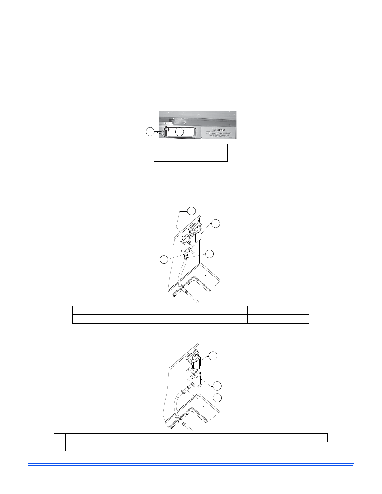
2 Return air smoke detector - shipped position . . . . . . . . . . . . . . . . . . . . . . . . . . . . . . . . . . . . . . . . . . . . . . . . . . . . . . . . . . . . . . . 7
3 Return air smoke detector - working position. . . . . . . . . . . . . . . . . . . . . . . . . . . . . . . . . . . . . . . . . . . . . . . . . . . . . . . . . . . . . . . . 7
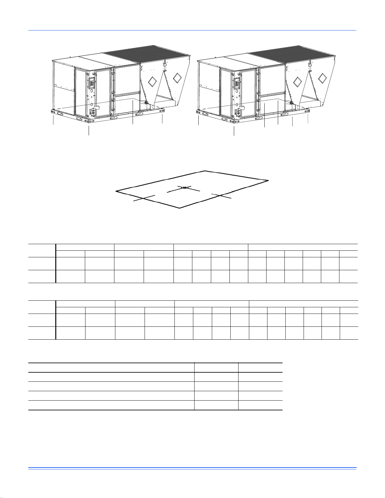
4 4 point and 6 point load weight . . . . . . . . . . . . . . . . . . . . . . . . . . . . . . . . . . . . . . . . . . . . . . . . . . . . . . . . . . . . . . . . . . . . . . . . . 10
5 Center of gravity. . . . . . . . . . . . . . . . . . . . . . . . . . . . . . . . . . . . . . . . . . . . . . . . . . . . . . . . . . . . . . . . . . . . . . . . . . . . . . . . . . . . . 10
6 ZM10-12 physical dimensions . . . . . . . . . . . . . . . . . . . . . . . . . . . . . . . . . . . . . . . . . . . . . . . . . . . . . . . . . . . . . . . . . . . . . . . . . . 11
7 ZM10-12 unit bottom duct openings . . . . . . . . . . . . . . . . . . . . . . . . . . . . . . . . . . . . . . . . . . . . . . . . . . . . . . . . . . . . . . . . . . . . . 12
8 ZM10-12 unit electrical entry . . . . . . . . . . . . . . . . . . . . . . . . . . . . . . . . . . . . . . . . . . . . . . . . . . . . . . . . . . . . . . . . . . . . . . . . . . . 13
9 ZM10-12 unit side duct openings . . . . . . . . . . . . . . . . . . . . . . . . . . . . . . . . . . . . . . . . . . . . . . . . . . . . . . . . . . . . . . . . . . . . . . . . 14
10 ZM10-12 unit left duct opening . . . . . . . . . . . . . . . . . . . . . . . . . . . . . . . . . . . . . . . . . . . . . . . . . . . . . . . . . . . . . . . . . . . . . . . . . 14
11 ZM10-12 roof curb . . . . . . . . . . . . . . . . . . . . . . . . . . . . . . . . . . . . . . . . . . . . . . . . . . . . . . . . . . . . . . . . . . . . . . . . . . . . . . . . . . . 15
12 ZM10-12 transition roof curb . . . . . . . . . . . . . . . . . . . . . . . . . . . . . . . . . . . . . . . . . . . . . . . . . . . . . . . . . . . . . . . . . . . . . . . . . . . 15
13 Side panels with hole plugs . . . . . . . . . . . . . . . . . . . . . . . . . . . . . . . . . . . . . . . . . . . . . . . . . . . . . . . . . . . . . . . . . . . . . . . . . . . . 16
14 Return down flow plenum with panel . . . . . . . . . . . . . . . . . . . . . . . . . . . . . . . . . . . . . . . . . . . . . . . . . . . . . . . . . . . . . . . . . . . . . 16
15 Condensate drain . . . . . . . . . . . . . . . . . . . . . . . . . . . . . . . . . . . . . . . . . . . . . . . . . . . . . . . . . . . . . . . . . . . . . . . . . . . . . . . . . . . . 17
16 Field wiring disconnect - cooling unit with or without electric heat and all units with a VFD option . . . . . . . . . . . . . . . . . . . . . . 19
17 Field wiring disconnect - cooling unit with gas heat without a VFD option. . . . . . . . . . . . . . . . . . . . . . . . . . . . . . . . . . . . . . . . . 20
18 Typical Smart Equipment™ control wiring . . . . . . . . . . . . . . . . . . . . . . . . . . . . . . . . . . . . . . . . . . . . . . . . . . . . . . . . . . . . . . . . . 21
19 Belt adjustment . . . . . . . . . . . . . . . . . . . . . . . . . . . . . . . . . . . . . . . . . . . . . . . . . . . . . . . . . . . . . . . . . . . . . . . . . . . . . . . . . . . . . 28
20 Altitude and temperature correction factors . . . . . . . . . . . . . . . . . . . . . . . . . . . . . . . . . . . . . . . . . . . . . . . . . . . . . . . . . . . . . . . . 29
21 Unit control board. . . . . . . . . . . . . . . . . . . . . . . . . . . . . . . . . . . . . . . . . . . . . . . . . . . . . . . . . . . . . . . . . . . . . . . . . . . . . . . . . . . . 37
22 SE-ECO1001-0 economizer controller. . . . . . . . . . . . . . . . . . . . . . . . . . . . . . . . . . . . . . . . . . . . . . . . . . . . . . . . . . . . . . . . . . . . 47

5703827-XIM-A-0319
Johnson Controls Ducted Systems 3
General
ZM units are single package air conditioners that are designed for outdoor installation on a rooftop or slab and for non-residential
use. These units are completely assembled on rigid, permanently attached base rails. All piping, refrigerant charge, and electrical
wiring is factory installed and tested. The units require electric power and duct connections.
These HVAC appliances are classified as not accessible to the general public.
Safety considerations
This is a safety alert symbol. When you see this symbol on labels or in manuals, be alert to the potential for personal injury.
Understand and pay particular attention the signal words DANGER, WARNING or CAUTION.
DANGER indicates an imminently hazardous situation, which, if not avoided, will result in death or serious injury.
WARNING indicates a potentially hazardous situation, which, if not avoided, could result in death or serious injury.
CAUTION indicates a potentially hazardous situation, which, if not avoided may result in minor or moderate injury. It is also used
to alert against unsafe practices and hazards involving only property damage.
These appliances are not intended for use by people (including children) with reduced physical, sensory or mental capabilities, or
lack of experience and knowledge, unless they have been given supervision or instructions concerning use of the appliance by a
person responsible for their safety. Children should be supervised to ensure that they do not play with the appliance.
These appliances can be installed to a maximum height of 10000 ft (3000 m) above sea level.
These appliances shall be installed in accordance with national wiring regulations.
WARNING
Improper installation may create a condition where the operation of the product
could cause personal injury or property damage. Improper installation, adjustment,
alteration, service or maintenance can cause injury or property damage. Refer to
this manual for assistance or for additional information, consult a qualified
contractor, installer or service agency.
CAUTION
This product must be installed in strict compliance with the installation instructions
and any applicable local, state and national codes including, but not limited to
building, electrical, and mechanical codes.
WARNING
Before performing service or maintenance operations on unit, turn off main power
switch to unit. Electrical shock could cause personal injury. Improper installation,
adjustment, alteration, service or maintenance can cause injury or property damage.
Refer to this manual. For assistance or additional information consult a qualified
installer or service agency.
CAUTION
This system uses R-410A refrigerant which operates at higher pressures than R-22.
No other refrigerant may be used in this system. Gauge sets, hoses, refrigerant
containers, and recovery systems must be designed to handle R-410A. If you are
unsure, consult the equipment manufacturer. Failure to use R-410A compatible
servicing equipment may result in property damage or injury.

5703827-XIM-A-0319
4Johnson Controls Ducted Systems
Due to system pressure, moving parts, and electrical components, installation and servicing of air conditioning equipment can be
hazardous. Only qualified, trained service personnel must install, repair, or service this equipment. Untrained personnel can perform
basic maintenance functions of cleaning coils and filters and replacing filters.
Observe all precautions in the literature, labels, and tags that accompany the equipment whenever you work on air conditioning
equipment. The installation must conform with local building codes.
Wear safety glasses and work gloves. Use a quenching cloth and have a fire extinguisher available during brazing operations.
Inspection
As soon as you receive a unit, inspect the unit for possible damage during transit. If damage is evident, note the extent of the
damage on the carrier’s freight bill. A separate request for inspection by the carrier’s agent should be made in writing.
Reference
Additional information is available in the following reference forms:
• Technical Guide - ZM10-12 5708826
Renewal parts
Contact your local Ducted Systems parts distribution center for authorized replacement parts.
Approvals
• For use as a cooling only unit.
• For outdoor installation only.
• For installation on combustible material and may be installed directly on combustible flooring or, in the U.S., on wood flooring
or Class A, Class B or Class C roof covering materials.
WARNING
Electrical shock, fire or explosion hazard
Failure to follow safety warnings exactly could result in dangerous operation, serious
injury, death or property damage.
Improper servicing could result in dangerous operation, serious injury, death or
property damage.
• Before servicing the unit, disconnect all electrical power to the unit.
• When servicing controls, label all wires prior to disconnecting. Reconnect the wires
correctly.
• Verify proper operation after servicing.
CAUTION
This product must be installed in strict compliance with the enclosed installation
instructions and any applicable local, state and national codes including, but not
limited to, building, electrical, and mechanical codes.
CAUTION
This product must be installed in strict compliance with the enclosed installation
instructions and any applicable local, state, and national codes including, but not
limited to, building, electrical, and mechanical codes.

5703827-XIM-A-0319
Johnson Controls Ducted Systems 5
WARNING
Improper installation may create a condition where the operation of the product
could cause personal injury or property damage.
CAUTION
This system uses R-410A refrigerant which operates at higher pressures than R-22.
No other refrigerant may be used in this system.

5703827-XIM-A-0319
6Johnson Controls Ducted Systems
Nomenclature
ZM 10 C00B 7 A 1 U
Product Category
ZM = Pkg AC R410A Middle East
(High Ambient and High Efficiency)
Voltage
Product Generation
1 = First Generation
Heat Type
C = Cooling only
Nominal Cooling Capacity
10 = 10 Ton / 35 kW
12 = 12.5 Ton / 43.75 kW
See catalog for ratings at 95°F, 118.4°F, and 125.6°F
Blower Options
Special Options - Country
U = Kuwait
Q = Qatar
E = Emirates, others
A = Standard cabinet
E = Stainless steel drain pan
1 = Standard throwaway filters
2 = 2 in. pleated filters (MERV 8)
3 = 4 in. pleated filters (MERV 13)
4 = Coil guard (CG) and standard filters
5 = CG and 2 in. pleated filters
6 = CG and 4 in. pleated filters
Cabinet Options
A = No economizer
Service Options
1 = No service options
B = PHM (phase monitor as standard)
C = DFS (dirty filter switch)
D = SSD (supply air smoke detector)
E = RSD (return air smoke detector)
F = PHM, DFS
G = PHM, SSD
H = PHM, RSD
J = DFS, SSD
K = DFS, RSD
L = SSD, RSD
M = PHM, DFS, SSD
N = PHM, DFS, RSD
P = PHM, SSD, RSD
Q = DFS, SSD, RSD
R = PHM, DFS, SSD, RSD
Additional Options
Outdoor Air Options
A = Standard Indoor and Outdoor Coils
B = E-Coat Condenser Outdoor Coil Only
C = E-Coat Evaporator Coil Only
F = E-Coat Condenser and Evaporator Coils
Heat Capacity
00 = Cooling only (no heat)
B = Standard static
7 = 380/415V-3-50Hz
Refrigeration
Sensor Options
Controls
1A
A = Smart Equipment™
A = None (units come standard with
factory-installed supply air, return air,
and outdoor air temperature sensors)
Nomenclature for 10 to 12.5 Ton / 35 kW to 43.75 kW Model Numbers
A
1A
A1

5703827-XIM-A-0319
Johnson Controls Ducted Systems 7
Installation
Installation safety information
Read these instructions before you install the appliance. This is an outdoor cooling unit. The installer must assure that these
instructions are made available to the consumer. Instruct the customer to retain the instructions for future reference.
• Install this unit only in a location and position as specified on page 8 of these instructions.
Preceding installation
1. Remove the two screws that hold the brackets in fork-lift slots on the side of the unit.
t
Figure 1: Unit shipping bracket
2. Turn each bracket toward the ground. The protective plywood covering drops to the ground.
3. If an optional return air smoke detector is installed, you must move the return air sensor from the factory shipped position
(upside down) to the working position (right side up). Then slide the flex tube over the stub and tighten, see Figure 3.
t
Figure 2: Return air smoke detector - shipped position
t
Figure 3: Return air smoke detector - working position
A Bracket screws
B Bracket
A Flex tube secured to the bracket for shipping C Controller
B Return air sensor in the shipped position D Wire tie
A Controller C Flex tube in the working position
B Return air sensor in the working position
AB
B
C
D
A
B
C
A

5703827-XIM-A-0319
8Johnson Controls Ducted Systems
Limitations
The units must be installed in accordance with the following standards:
In the U.S.A.:
• National Electrical Code, ANSI/NFPA No. 70 - Latest Edition
• Local building codes
In Canada:
• Canadian Electrical Code, CSA C22.1
• Installation Codes, CSA - B149.1.
• Local plumbing and waste water codes, and
• Other applicable local codes.
For export only:
• Building and installation codes enforced by the local government of the country where the unit is installed.
Location
Use the following guidelines to select a suitable location for these units:
• The unit is designed for outdoor installation only.
• Condenser coils must have an unlimited supply of air. Where a choice of location is possible, position the unit on either the
north or east side of building.
• The unit is suitable for mounting on roof curb.
• For ground level installation, use a level concrete slab with a minimum thickness of 4 in. (102 mm). The length and width
should be at least 6 in. (152 mm) greater than the unit base rails. Do not tie slab to the building foundation.
• Roof structures must be able to support the weight of the unit and its options and accessories. The unit must be installed on a
solid, level roof curb or appropriate angle iron frame.
• Maintain level tolerance to 1/2 in. (13 mm) across the entire width and length of unit.
Rigging and handling
Exercise care when you move the unit. Do not remove any packaging until the unit is near the place of installation. To rig the unit,
attach chain or cable slings to the lifting holes provided in the base rails. Spreader bars, whose length exceeds the largest dimension
across the unit, MUST be used across the top of the unit.
Table 1: ZM10-12 unit limitations
Size (tons/KW) Unit voltage
Unit limitations
Applied voltage Outdoor DB temp Outdoor DB temp
Minimum Maximum Maximum (°F) Maximum (°C)
ZM10
(10/35) 380/415-3-50 342 457 125 52
ZM12
(12.5/43.75) 380/415-3-50 342 457 125 52
WARNING
Do not permit overhanging structures or shrubs to obstruct condenser air discharge
outlet, combustion air inlet, or vent outlets.
CAUTION
If a unit is to be installed on a roof curb other than a Ducted Systems roof curb, you
must apply gasketing to all surfaces that come in contact with the underside of the
unit.

5703827-XIM-A-0319
Johnson Controls Ducted Systems 9
Units may be moved or lifted with a forklift. Slotted openings in the base rails are provided for this purpose.
The length of the forks must be a minimum of 60 in. (1524 mm).
CAUTION
Before lifting, make sure the unit weight is distributed equally on the rigging cables
so it will lift evenly.
CAUTION
All panels must be secured in place when the unit is lifted.
The condenser coils should be protected from rigging cable damage with plywood or
other suitable material.

5703827-XIM-A-0319
10 Johnson Controls Ducted Systems
ZM10-12 unit weights
Figure 4: 4 point and 6 point load weight
Figure 5: Center of gravity
Table 2:ZM10-12 weights and dimensions - imperial
Size
(tons)
Weight (lbs.) Center of gravity (in.) 4 point load location (lbs.) 6 point load location (lbs.)
ShippingOperating X Y ABCDABCDEF
ZM10
(10) 1345 1340 51 24 226 307 464 342 144 174 216 326 263 217
ZM12
(12.5) 1435 1430 51 25 256 338 475 361 163 195 236 332 274 230
Table 3:ZM10-12 weights and dimensions - metric
Size
(kW)
Weight (kg) Center of gravity (mm) 4 point load location (kg) 6 point load location (kg)
ShippingOperating X Y ABCDABCDEF
ZM10
(10) 610 608 1303 597 103 139 210 155 65 79 98 148 119 98
ZM12
(43.75) 651 649 1285 622 116 153 216 164 74 88 107 151 124 104
Table 4: ZM10-12 unit accessory weights
Unit Accessory Weights (lbs.) Weights (kg)
Curb Rigid 14 in. (356 mm) Small Footprint 94 66
Curb Rigid 14 in. (356 mm) Large Footprint 126 61
Curb Rigid 24 in. (610 mm) Small Footprint 148 61
Curb Rigid 24 in. (610 mm) Large Footprint 222 61
A
LEFT
D
C
FRONT BA
LEFT
B
CD
FRONT E
F
XY
LEFT FRONT

5703827-XIM-A-0319
Johnson Controls Ducted Systems 11
Figure 6: ZM10-12 physical dimensions
1 See detail B for drain location
Table 5: ZM10-12 unit physical dimensions - imperial
Unit model number Dimension (in.)
ABCDEF
ZM10
ZM12 50 3/4 119 1/2 30 3/16 24 3/16 17 3/16 6 3/16
Table 6: ZM10-12 unit physical dimensions - metric
Unit model number Dimension (mm)
ABCDEF
ZM10
ZM12 1289 3035 767 614 437 157
Table 7: ZM10-12 unit clearances
Direction Distance (in.) Distance (mm) Direction Distance (in.) Distance (mm)
Top1
1. Units must be installed outdoors. Make sure that overhanging structures or shrubs do not obscure the condenser air discharge outlet.
72 1829 Right 12 305
Front 36 914 Left 36 914
Rear 36 914 Bottom2
2. Units may be installed on combustible floors made from wood or class A, B or C roof covering materials.
00
15.23 in.
381 mm
29.03 in.
736.6 mm
29.03 in.
736.6 mm
14.85 in.
355.6 mm
14.85 in.
355.6 mm
15.23 in.
381 mm
28.86 in.
711.2 mm
29.66 in.
29.66 mm
44.09 in.
1117.6 mm
Ø 24.58 TYP. 4 PL.
FRONT
C
D
E
F
B
4 3/16 in.
101.6 mm
27 5/16 in.
685.8 mm 89 in.
2261 mm
21 3/16 in.
533.4 mm
11 3/8 in.
279.4 mm
A
LEFT
59 in.
1499 mm

5703827-XIM-A-0319
12 Johnson Controls Ducted Systems
Top view
Figure 7: ZM10-12 unit bottom duct openings
Figure 7 shows the bottom power, control, and convenience outlet wiring entry.
A Return air DFront
B Supply air EBottom condensate drain
CRight FLeft
20 1/8 in. 19 1/8 in. 17 1/8 in.
6 13/16 in.
6 13/16 in.
32 11/16 in.
14 1/2 in.
16 3/8 in.
18 1/16 in.
25 9/16 in.
12 5/16 in.
27 1/2 in. 24 in.
21 in.
18 in.
89 in.
2261 mm
830 mm
173 mm
173 mm
690 mm
457 mm
610 mm
533 mm
511 mm 486 mm 435 mm
368 mm
416 mm
459 mm
649 mm
313 mm
(
%
$
'
)
&
Ø 2.469 in.
3X Ø 0.875 in.
22 mm
63 mm

5703827-XIM-A-0319
Johnson Controls Ducted Systems 13
Figure 8: ZM10-12 unit electrical entry
Item Description
A Disconnect switch cover
B Power entry Ø 2-1/2 in. (64 mm)
CControl entry Ø 7/8 in. (22 mm)
DPower entry Ø 2-1/2 in. (64 mm)
EConvenience outlet cover
FConvenience outlet power entry Ø 7/8 in. (22 mm)
A
B
C
D
E
F

5703827-XIM-A-0319
14 Johnson Controls Ducted Systems
Figure 9: ZM10-12 unit side duct openings
Figure 10: ZM10-12 unit left duct opening
Item Description
A Dot plugs
Table 8:ZM10-12 side duct dimensions
Unit model number Dimension (in.) Dimension (mm)
ABCDABCD
ZM10
ZM12 28 1/4 18 1/16 28 1/4 18 1/4 718 459 718 464
Table 9:ZM10-12 left/end duct dimensions
Unit model number Dimension (in.) Dimension (mm)
A B C ABC
ZM10
ZM12 30.358 22.580 22.330 771.09 573.53 567.18
2-7/8 in.
50.8 mm
5-5/32 in.
131 mm
D
C31-5/8 in.
787.4 mm
18-1/4 in.
464 mm
B
A
$
4-5/16 in.
110 mm
A
C
B

5703827-XIM-A-0319
Johnson Controls Ducted Systems 15
Roof curbs
Figure 11: ZM10-12 roof curb
Figure 12: ZM10-12 transition roof curb
Roof curb components
Item Description
A Return air
B Supply air
C Right side of the unit
D Front side of the unit
E 2 typ.
F Insulated deck under the condenser section
G Insulated deck under the compressor section
$
%
&
'
(
*
)
80-5/8 in.
2050 mm
20 in.
510 mm
20 in.
510 mm 6 in.
150 mm
30 in.
760 mm
50-1/2 in.
1285 mm
8 in.
205 mm
14 in.
355 mm
50 mm
&
'
(
%
$
80-5/8 in.
2050 mm
50-1/2 in.
1285 mm
30-1/2 in.
775 mm
10 in.
255 mm
59-1/4 in.
1505 mm
64-1/4 in.
1630 mm
76-5/8 in.
1945 mm
94 in.
2390 mm
50 mm

5703827-XIM-A-0319
16 Johnson Controls Ducted Systems
Ductwork
Ductwork must be designed and sized according to the methods in Manual D of the Air Conditioning Contractors of America (ACCA)
or as recommended by any other recognized authority such as ASHRAE or SMACNA.
A closed return duct system must be used. The supply and return air duct connections at the unit must be made with flexible joints to
minimize noise. The supply and return air duct systems must be designed for the CFM and static pressure requirements of the job.
They must not be sized to match the dimensions of the duct connections on the unit. See the previous figures for bottom and side air
duct openings.
Duct covers
Units are shipped with the side duct openings covered. For a bottom duct application, no duct cover changes are necessary. For a
side duct application, complete the following steps.
1. Remove the side duct covers.
2. Orient the supply panel with the painted surface up.
3. Slide the supply panel along the bottom of the unit.
4. Secure the supply panel with the factory-installed bracket and two screws.
5. Orient the return panel with the painted surface down.
6. Install the return panel over the corresponding side duct. The painted surface must face the down flow duct opening.
7. Secure the return panel with four screws.
Figure 13: Side panels with hole plugs
Note: Note the orientation of the panel with the insulation side facing up.
Figure 14: Return down flow plenum with panel
CAUTION
When you fasten the ductwork to the side duct flanges on the unit, insert the screws
through the duct flanges only. DO NOT insert the screws through the casing.
Outdoor ductwork must be insulated and water-proofed.

5703827-XIM-A-0319
Johnson Controls Ducted Systems 17
Condensate drain
The side condensate drain can be ordered re-oriented to the rear of the cabinet to facilitate condensate piping. A condensate drain
connection is available through the base pan for piping inside the roof curb.
Note: Plumbing must conform to local codes.
To install the connection, complete the following steps.
1. Trap the connection according to Figure 15.
Note: You must protect the trap and drain lines from freezing.
2. Install the condensate drain line from the 1 inch NPT female connection on the unit to an open drain. Use a sealing compound
on male pipe threads.
Figure 15: Condensate drain
Compressors
The compressor used in this product is specifically designed to operate with R-410A refrigerant and cannot be interchanged.
The compressor also uses a refrigerant oil that is extremely hygroscopic, this means that it absorbs water readily. They can absorb 15
times as much water as other oils designed for HCFC and CFC refrigerants. Take all necessary precautions to avoid exposure of the oil
to the atmosphere.
R-410A compressor lubricants are known to cause long term damage to some synthetic roofing materials.
CAUTION
This system uses R-410A refrigerant that operates at higher pressures than R-22.
No other refrigerant may be used in this system.
CAUTION
Do not leave the system open to the atmosphere. Unit damage could occur if
moisture is absorbed by the refrigerant in the system. This type of oil is highly
susceptible to moisture absorption.
CAUTION
Exposure, even if immediately cleaned up, may cause embrittlement (leading to
cracking) to occur in one year or more. When you perform any service that may risk
exposure of compressor oil to the roof, take precautions to protect the roofing.
3 in. 76.2 mm minimum

5703827-XIM-A-0319
18 Johnson Controls Ducted Systems
Procedures that risk oil leakage include, but are not limited to, compressor replacement, repairing refrigerant leaks, and replacing
refrigerant components such as a filter drier, pressure switch, metering device, or coil.
Units are shipped with compressor mountings that are factory-adjusted and ready for operation.
Filters
Two-inch filters are supplied with each unit. Four-inch filters may be used with no modification to the filter racks. Filters must always
be installed ahead of the evaporator coil and must be kept clean or replaced with filters of the same size and type. Dirty filters reduce
the capacity of the unit and result in frosted coils or safety shutdown. See the physical data tables, for the number and size of filters
needed for the unit. The unit must not be operated without filters properly installed.
Power and control wiring
Field wiring to the unit, fuses, and disconnects must conform to provisions of National Electrical Code (NEC), ANSI/NFPA No. 70 –
Latest Edition (in U.S.A.), current Canadian Electrical Code C221, and/or local ordinances. The unit must be electrically grounded in
accordance with NEC and CEC as specified above and/or local codes.
Means for disconnection must be incorporated in the fixed wiring according to the wiring rules. The disconnect incorporated in the
fixed wiring must be provided and field installed by the installer.
Voltage tolerances which must be maintained at the compressor terminals during starting and running conditions are indicated on
the unit rating plate and in Table 1.
The internal wiring harnesses provided with this unit are an integral part of the design certified unit. Field alteration to comply with
electrical codes should not be required. If any of the wire supplied with the unit must be replaced, the replacement wire must be of
the type shown on the wiring diagram and the same minimum gauge as the replaced wire.
A disconnect must be used for these units.
NOTE: Not all local codes allow the mounting of a disconnect on the unit. Confirm compliance with the applicable local code before
you mount a disconnect on the unit.
Electrical line must be sized properly to carry the load. Use copper conductors only. Each unit must be wired with a separate branch
circuit fed directly from the meter panel and properly fused.
CAUTION
Do not loosen compressor mounting bolts.
CAUTION
380/415-3-50 units control transformers are factory wired for 415v. Change the tap
on the transformer for 380v operation. See the unit wiring diagram.
CAUTION
Avoid damage to the internal components if you drill holes for the disconnect
mounting.
CAUTION
When you connect electrical power and control wiring to the unit, water-proof
connectors must be used so that water or moisture cannot be drawn into the unit
during normal operation. The above water-proofing conditions also apply when you
install a field supplied disconnect switch.

5703827-XIM-A-0319
Johnson Controls Ducted Systems 19
Power wiring detail
Units are factory wired for the voltage shown on the unit nameplate. See Electrical data on page 22 to size power wiring, fuses, and
the disconnect switch.
Power wiring is brought into the unit through the side of the unit or the basepan inside the curb.
Figure 16:Field wiring disconnect - cooling unit with or without electric heat and all units with a VFD option
CAUTION
When you install equipment in a facility with a 3-phase high-leg delta power supply,
you must take care to ensure that the high-leg conductor is not attached to either of
the two legs of the (single phase, direct drive) X13 or ECM motors. Failure to do so
can result in the motor acting erratically or not running at all.
Check for the high leg conductor by checking voltage of each phase to ground.
Example: A or L1 phase to ground, voltage reading is 120V. B or L2 phase to
ground, voltage reading is 195 to 208V. C or L3 phase to ground, voltage reading is
120V. Therefore B or L2 phase is the high Leg. The high should always be wired to
the center or B or L2 tap.
Note: Check all three phase motors and compressors for proper rotation after
making a change. If it is necessary to change 3 phase motor rotation, swap A or L1
and C or L3 only.
THREE
PHASE
POWER
SUPPLY
FACTORY OR FIELD
SUPPLIED DISCONNECT
GROUND
LUG
TERMINAL BLOCK TB1

5703827-XIM-A-0319
20 Johnson Controls Ducted Systems
Figure 17: Field wiring disconnect - cooling unit with gas heat without a VFD option
L1
T1
L2
T2 T3
L3
THREE
PHASE
POWER
SUPPLY
FACTORY OR FIELD
SUPPLIED DISCONNECT
GROUND
LUG
CONTACTOR 1M
This manual suits for next models
2
Table of contents
Other York International Blower manuals